In this post I have explained how to construct a vehicle counter circuit that can count the number of vehicles entered in a parking lot at office building, schools, libraries, restaurants, hotels etc. The proposed project can count up to 999 vehicles especially cars and two wheelers and it can even count long vehicles like bus, vans and trucks.
Block diagram:

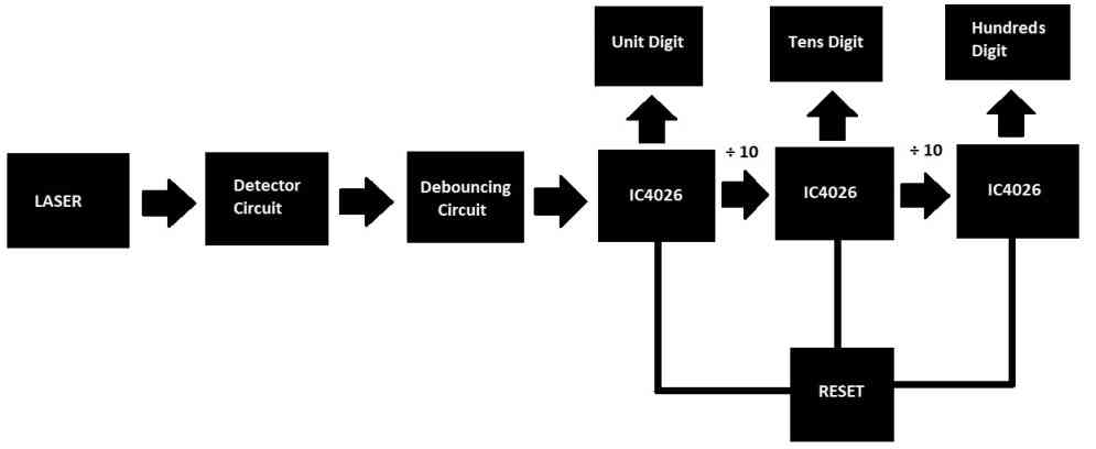
The vehicle parking counter circuit we are going to build will be based on the above functional blocks.
- At the left hand side we have a laser module which emits laser beam. The power output of the beam should be greater than or equal to 5mW so that the laser beam is sufficiently bright.
- A detector circuit receives the laser beam and when the laser beam is interrupted the detector stage gives out an appropriate signal to debouncing stage.
- The debouncing stage is responsible for giving out a clean pulse to the counter stage. The debouncing stage removes unwanted surplus pulses received by the detector circuit.
- The next three stages are counters which can display counts up to 999. There are three IC 4026s which will drive three common cathode LED displays.
- The cascaded ICs gives output 1 pulse for every ten pulses it received at clock input, thus we can derive units, tens and hundreds digit places.
- A reset button is connected to all IC 4026s so that a user can reset the count to zero according to their circumstances if necessary.
Circuit diagram:
We will be exploring the circuit diagram one stage at a time so that we can grasp the circuit better.
- Laser setup.
- LDR detector and debouncing circuit.
- 7 segment counter circuit.
Laser setup:
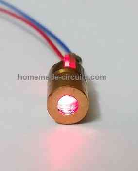
A 5V laser module is utilized in this project and the optical power output of the module can be equal to or greater than 5mW which provides sufficient brightness.
On the receiver side we need to make the below illustrated setup so that the receiver can receive the laser beam with least interference with ambient light sources.

You need to find or make a hollow cylindrical tube that is at least 5 cm in length and a small opening (1.5 to 2 cm) at the front and the LDR is placed at rear end of the tube which is sealed with suitable material to prevent light entering through rear. It is recommended to paint the interior of the tube with black paint.
The laser and the hollow tube must be aligned in such a way that laser beam directly hits the LDR. The vehicles pass between the laser transmitter and LDR setup. Please leave sufficient gap between the two so that vehicles can move freely.
Detector and Debouncing circuit:
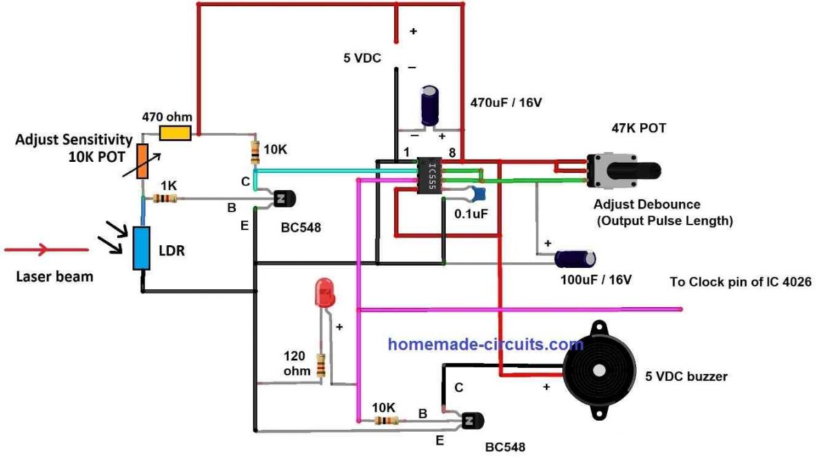
The detector circuit consists of a LDR, a NPN transistor and few resistors. When the laser hits the LDR, its resistance drop to a very low value and negative signal will be available at the base terminal of the transistor, this will prevent the transistor turning ON.
When a vehicle interrupts the laser beam LDR’s resistance increases significantly and positive signal will be available at the base (positive supply via potentiometer and 470 ohm resistor), this will turn ON the transistor and gives out negative signal (at collector terminal) to IC555’s pin #2 which is necessary for triggering IC555’s output pin high.
The debouncing circuit is nothing but a monostable multivibrator, once a negative pulse is received by IC 555 its output pin #3 will turn HIGH and it will ignore pulses from the detector circuit until the IC 555 goes back to its stable state (idle output is LOW), this will gives out a clean positive pulse to the next stage.
The debouncing circuit is implemented to ignore multiple pulses generated by the moments of the vehicles especially with two wheels where the laser beam could get interrupted multiple times. A 47K ohm potentiometer is provided to adjust debouncing time (maximum 5 seconds).
A buzzer and LED are provided to indicate that a vehicle has entered the parking lot and a count has been registered.
7 Segment display counter circuit:
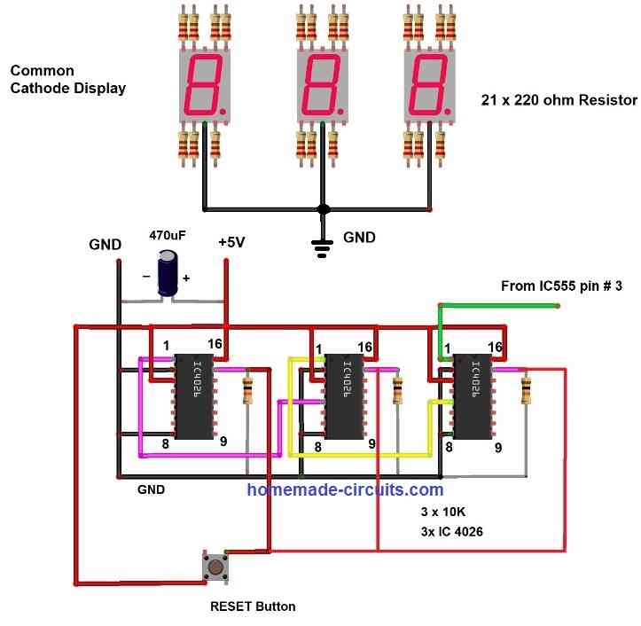
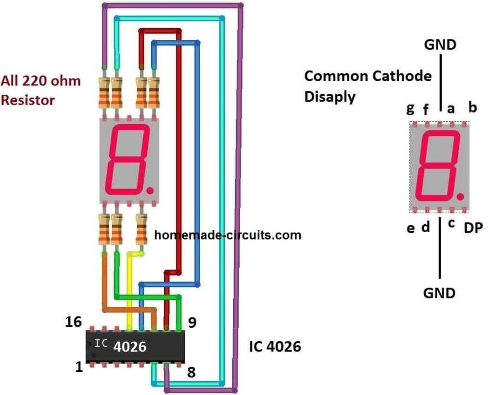
This stage of the vehicle parking counter circuit is responsible for counting number of vehicles entered in the parking lot. Before I have explained the above circuit, we need to understand IC 4026’s pin diagram and what each of the 16 pins does and you will find it very easy to understand.
Pin diagram of IC4026:
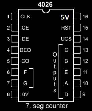
- Pin 1: Clock input.
- Pin 2: Clock inhibit, Ignores clock input if this pin is connected to high. During normal operation pin 2 is connected to GND.
- Pin 3: Digit enable, when this pin is connected to high, the output A to G is enabled.
- Pin 5: Carry out, when the IC receives every 10th pulse this pins turns high which can be fed to another IC 4026’s clock input pin, thus we cascade them. Cascading can be done with any number of IC 4026s to get large numbers.
- Pins 6, 7, 9, 10, 11, 12, 13 are segments A, B, C, D, E, F, G respectively.
- Pin 8: GND.
- Pin 15: Reset, when this pin is turned high the count will turn zero. During normal operation this pin is connected to GND.
- Pin 16: Vcc.
By just understanding the above pin description you can understand the circuit why the pins are connected in a certain way. The 10K resistors are used to pull the pin #15 to down (GND) during normal operation and when you press the reset button the pin 15 turns high which resets all the IC 4026s to zero.
Note: You can place the proposed vehicle parking lot counter circuit at the entrance and also at exit. By doing this you can know how many vehicles have entered the parking lot and how many left the parking lot and by doing the below shown calculation we can find number of vehicles currently parked:
Entrance count – Exit count = Vehicles parked currently
Can this be used outdoors for multiple enter/exit point? I would thinks so but the outdoor part is the biggest concern.
yes it can be installed outdoors with an electric supply