The following useful circuit of a TV antenna amplifier was sent to me by an avid reader of this blog Mr. Miljenko Farkas. I am extremely grateful to him for his kind contribution to this site.
Here's what he wrote in his email:
I've sent you a schematic of a TV antenna amplifier that can assist boost reception in places with poor signal strength or under challenging TV signal circumstances.
Although this amplifier has performed admirably in Europe I'm not sure how well it would function elsewhere.
This is an opportunity to test it out since I believe certain designers could find it to be an intriguing challenge. The amplifier should be placed at the top of the antenna once it is constructed and the power supply or rectifier circuit should be near the television.
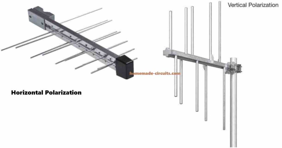
Both vertical and horizontal logarithmic antenna types are supported by the amplifier's architecture.
There is just one power line that runs from the TV to the antenna which supplies both power and signal and both antennas can connect to the amplifier simultaneously.
That concludes this year. I hope 2025 brings you nothing but the finest!
Overview
So this antenna amplifier is made to really enhance how well your TV picks up signals especially in spots where the signals are kind of weak or just hard to get.
It works with two different kinds of polarization for logarithmic antennas which are vertical and horizontal. What it does is take the signals from both types and merges them into a single coaxial cable. This cable is responsible for carrying not just the boosted signal but also the power supply that the amplifier needs to work.
Now when it comes to where you should put this amplifier for it to work its best you want to place it really close to the antenna. This setup helps it do its job efficiently. Meanwhile the rectifier and power supply should be set up near your TV so everything runs smoothly.
Circuit Working
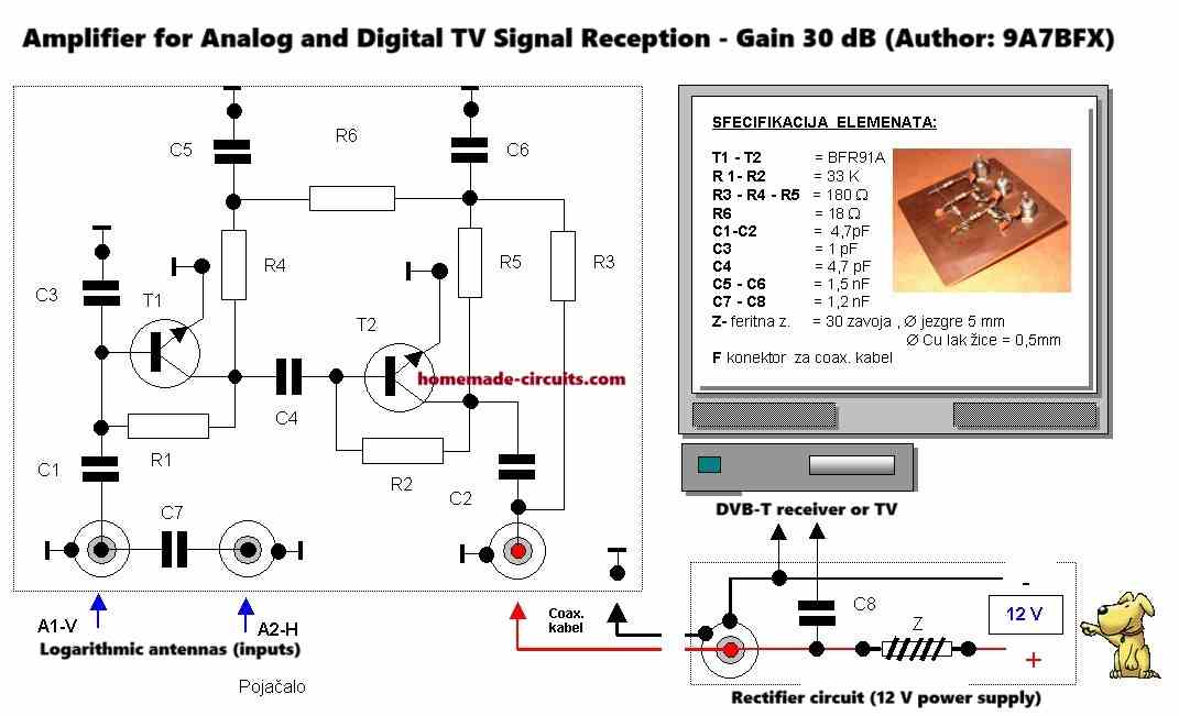
Amplifier Section Transistors (T1 and T2 - BFR91A):
These are high-frequency NPN transistors commonly used in RF amplifiers.
T1 and T2 form a two-stage amplifier.
The signal from the antennas is fed to T1, amplified, and passed to T2 for further amplification.
This cascading increases the overall gain, ensuring a 30 dB signal boost.
Capacitors (C1, C2, C3, C4, C5, C6):
C1 and C2 work like coupling capacitors passing the high-frequency signal while blocking DC components.
C3 and C4 are the bypass capacitors which stabilize the DC operating points of T1 and T2 by shorting high-frequency noise to ground.
C5 and C6 are used to fine-tune the circuits frequency response optimizing it for TV signal frequencies.
Resistors (R1 to R6):
R1 and R2 are the biasing resistors for the transistors for setting the operating point for stable amplification.
R3, R4, and R5 are the load resistors which determes the gain of each transistor stage.
R6 is the current-limiting resistor for ensuring proper current flow to the transistors.
Ferrite Core Inductor (Z):
A small inductor with 30 turns on a 5 mm core.
Acts as an impedance-matching element, ensuring minimal signal loss when interfacing with the coaxial cable.
Dual Input (A1-V and A2-H):
The circuit supports two separate logarithmic antennas for vertical (A1-V) and horizontal (A2-H) polarization.
These antennas are connected in parallel to the amplifier, enabling simultaneous reception of both polarizations.
Power Supply Section C7 and C8:
Act as DC filter capacitors to stabilize the power supply voltage.
Smooth out any ripples from the rectifier circuit to ensure clean power to the amplifier.
Coaxial Cable (Signal + Power):
A single coaxial cable carries both the amplified signal and the 12 V DC power supply to the amplifier.
The power is extracted at the amplifier end, while the signal is passed to the TV at the other end.
Rectifier Circuit:
Located near the TV this circuit converts AC from the mains to DC providing us the required 12 V for the amplifier.
Main Points for Installation Amplifier Placement:
The amplifier must be installed at the top of the antenna to minimize the signal loss from cable resistance and interference.
Power Line Sharing: The coaxial cable does two things, it powers the amplifier and also transmits the amplified signal back to the TV or receiver.
Compatibility: The circuit has been tested successfully in Europe wherein the TV signal frequencies and standards might be different.
Testing throughout outside the Europe is encouraged to verify the compatibility with other regional broadcasting standards.
Applications and Challenges Applications: This amplifier could be highly useful for the rural or the remote areas wherein TV signals are weak due to distance or obstacles.
Challenges: If used outside the Europe then the amplifier’s components might need some adjustment to match different regional TV frequency bands.
For example the values of the C5, C6, and Z might need tweaking some.
This circuit provides an interesting and practical solution for improving the TV reception and it gives a great opportunity for enthusiasts to experiment and adapt it to their specific needs...
I am an electronics engineer with over 15 years of hands-on experience. I am passionate about inventing, designing electronic circuits and PCBs, and helping hobbyists bring their projects to life. That is why I founded homemade-circuits.com, a website where I share innovative circuit ideas and tutorials. Have a circuit related question? Leave a comment.... I guarantee a reply!

Need Help? Please Leave a Comment! We value your input—Kindly keep it relevant to the above topic!