In this post I have explained how to select ferrite core material with the correct specifications for ensuring proper compatibility with a given SMPS circuit design
Why Ferrite Core
Ferrite is a wonderful core substance for transformers, inverters and inductors in the frequency spectrum 20 kHz to 3 MHz, owing to the benefits of reduced core expense and minimal core losses.
Ferrite is an effective stuff for high frequency (20 kHz to 3 MHz) inverter power supplies.
Ferrites should be employed in the saturating approach for low power, low frequency functioning ( <50 watts and 10 kHz). For high power functionality a 2 transformer layout, employing a tape wrapped core as the saturating core and a ferrite core as the output transformer, delivers optimum execution.
The 2 transformer model provides extraordinary efficiency fantastic frequency durability, and minimal switching drawdowns.
Ferrite cores is commonly used in fly-back transformer versions, that provide minimal core cost, reduced circuit expense and top voltage efficiency. Powder cores (MPP, High Flux, Kool Mμ®) produce softer saturation, greater Bmax and more advantageous temperature constancy and is often the preferred option in a number of flyback usages or inductors.
High frequency power supplies, either inverters and converters, propose cheaper price, and reduced weight and structure compared to traditional 60 hertz and 400 hertz power options.
Several cores in this specific segment are typical designs frequently used in the profession.
CORE MATERIALS
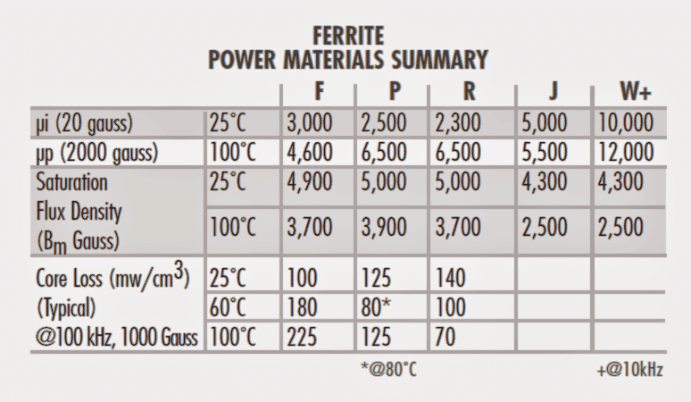
F, P, and R materials, facilitating the minimal core disadvantages and maximum saturation flux density, are recommended for high power/high temperature functionality. P material core deficits drop with temperature up to 70°C; R material losses decline to as much as 100°C.
J and W materials provide you with superior impedance for wide transformers, which makes them also recommended for low-level power transformers.
CORE GEOMETRIES
1) POT CORES
Pot Cores, are manufactured to pretty much encircle the wound bobbin. This facilitates safeguarding the coil from picking of of EMI from outside alternatives.
The pot core proportions pretty much all stick to IEC specifications to ensure that there exists interchangeability between companies. Both the plain and printed circuit bobbins are
on the market, as are mounting and assembly hardware.
Due to its layout, the pot core is usually a more high-priced core compared to different formats of a analogous size. Pot cores for substantial power purposes are not easily accessible.
2) DOUBLE SLAB AND RM CORES
Slab-sided solid center post cores are similar to pot cores, but yet possess a segment minimize off on either part of the skirt. Substantial entrances make it possible for bigger wires to be lodged and contributes to eliminating heat from the setup.
RM cores are similar to pot cores, however are fashioned to curtail pcb area, supplying a minimum of a 40% reductions in installation space.
Printed circuit or plain bobbins are obtainable. Straightforward 1 unit clamps enable hassle-free construction. Lower outline is achievable.
The sturdy middle piece delivers less core loss which in turn eliminates heat accumulation.
3) EP CORES
EP Cores are circular center-post cubical designs which surround the coil thoroughly with the exception of the printed circuit board terminals. The specific appearance eliminates the influence of air flow crevices established at mating walls in the magnetic track and gives you a more significant volume ratio to absolute area used. Safeguarding from RFs is pretty much great.
4) PQ CORES
PQ cores are intended distinctively for switched mode power supplies. The layout allows for an maximized ratio of bulk to winding region and surface area.
Therefore, both optimum inductance and winding surface are achievable with the absolute minimum core dimension.
The cores as a result afford optimum power output with the very least assembled transformer mass and dimension, along with occupying a bare minimum level of space on the printed circuit board.
Setting up with printed circuit bobbins and one bit clamps is made easy. This economical model assures much more homogeneous cross-sectional section; consequently cores often work with with a smaller amount of hot positions compared to with different layouts.
5) E CORES
E cores are cheaper than pot cores, while having the aspects of straightforward bobbin winding and uncomplicated assemblage. Gang winding is achievable for the bobbins put to use using these cores.
E cores never, all the same, present self-shielding. Lamination size E layouts are designed for accommodate commercially accessible bobbins in past times meant to conform the strip stampings of customary lamination measurements.
Metric and DIN sizes can also be found. E cores are typically embedded to various consistency, furnishing a variety of cross-sectional areas. Bobbins for these various cross sectional areas tend to be accessible commercially.
E cores are typically installed in unique orientations, in case preferred, grant a lowprofile.
Printed circuit bobbins can be found for low-profile fixing.
E cores are well-known designs on account of their more affordable rate, convenience of assembly and winding, and the organized prevalence of an assortment of hardware.
6) PLANAR E CORES
Planar E cores can be found in virtually all of the IEC conventional measurements, along with several of supplementary capacities.
Magnetics R material is flawlessly matched to planar shapes owing to its reduced AC core losses and minimal losses at 100°C.
Planar layouts in most cases have low turn numbers and agreeable thermal dissipation as opposed to standard ferrite transformers, and for that reason the ideal designs for space and effectiveness lead to increased flux densities. In those variations, the overall performance advantage of R material is principally quite notable.
The leg span and window elevation (B and D proportions) are flexible for individual purposes without new tooling. This makes it possible for the developer to fine-tune the finalized core specs to accurately fit with the planar conductor stack elevation, lacking any expended space.
Clips and clip slots are offered in numerous instances, that could be specifically effective for prototyping. I-cores are furthermore proposed standard, which allows even more adaptability in layout.
E-I planar patterns come in handy to enable effective face blending in high bulk production, as well as for creating gapped inductor cores whereby fringing drawdowns needs to be thoroughly regarded on account of the planar structure.
7) EC, ETD, EER AND ER CORES
These types of patterns are a mix between E cores and pot cores. Like E cores, they deliver an enormous gap on both sides. This enables satisfactory room for the bigger size wires necessary for reduced output voltage switched mode power supplies.
Aside from that it guarantees a circulation of air which maintains the construction colder.
The middle piece is circular, very similar to that of the pot core. One of the positive aspects of the circular central pillar is that the winding bears a smaller course period around it (11% faster) compared to the wire around a square type central pillar with an very same cross sectional area.
This cuts down on the losses of the windings by 11% and also makes it possible for the core to cope with an improved output ability. The circular central pillar additionally minimizes the spiked fold in the copper that transpires with winding on a square type central pillar.
8) TOROIDS
Toroids are cost-effective to produce; consequently, these are least expensive of most relevant core designs. Because no bobbin becomes necessary, accessory and setting up charges are negligible.
Winding is completed on toroidal winding equipment. Shielding attribute is pretty sound.
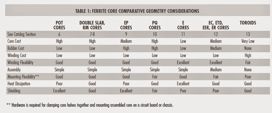
Overview
Ferrite geometries provide you with a huge choice in sizes and styles. When picking a core for power supply utilizations, specifications displayed in Table 1 ought to be assessed.
TRANSFORMER CORE SIZE SELECTION
The power processing capability on a transformer core is usually contingent on its WaAc product, in which Wa is the offered core window space, and Ac is the useful core cross-sectional space.
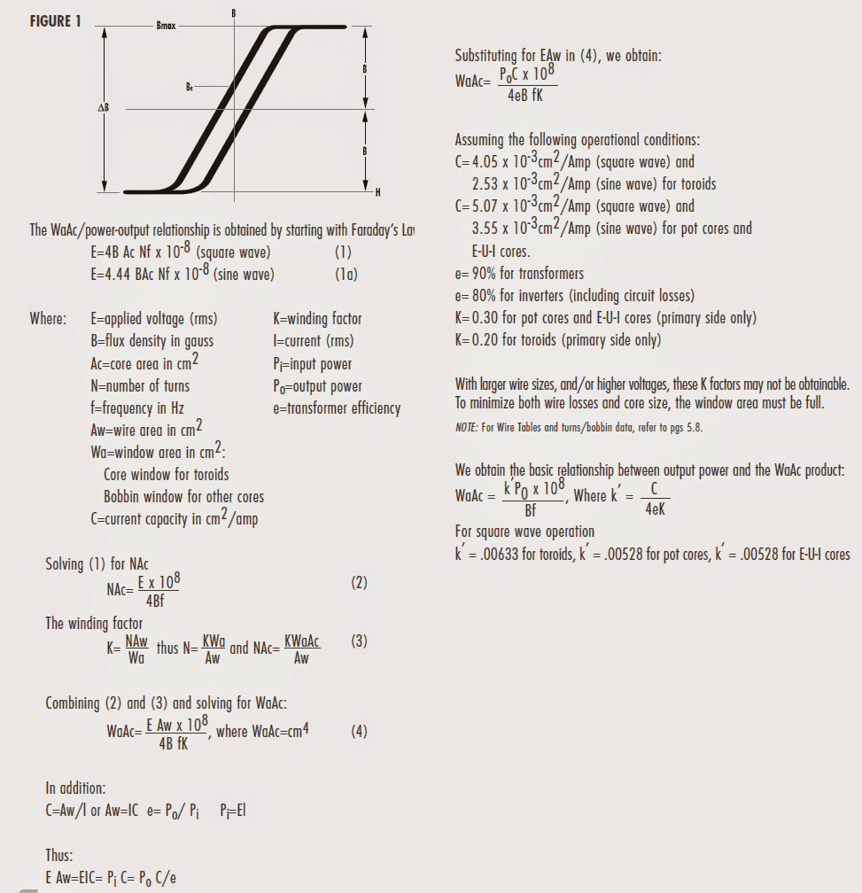
While the equation above enables WaAc to be modified depending on particular core geometry, the Pressman technique takes advantage of topology as the fundamental factor and enables the maker to designate current density.
GENERAL INFORMATION
A perfect transformer is but one that promises minimal core decline while demanding the very least volume of room.
The core loss in a particular core is specifically affected by the flux denseness along with the frequency. Frequency is the crucial factor regarding a transformer. Faraday’s Law indicates that as frequency speeds up, the flux density reduces correspondingly.
Core losing trades reduce a lot more in case the flux density falls compared to when frequency increases. As an illustration, when a transformer is operated at 250 kHz and 2 kG on R material at 100°C, the core failures would probably be around 400 mW/cm3.
If the frequency was made twice and most other limitations unscathed, as a result of Faraday’s law, the flux density would likely turn out to be 1kG and the resultant core drawdowns would be roughly be 300mW/cm3.
Standard ferrite power transformers are core loss restricted ranging from 50- 200mW/cm3. Planar models could be operated a lot more assertively, up to 600 mW/cm3, on account of more advantageous power dissipation and significantly less copper in the windings.
CIRCUIT Categories
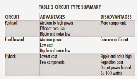
A number of basic feedback on the several circuits are: The push-pull circuit is effective since the device causes bi-directional usage of a transformer core, presenting an output with reduced ripple. In spite of this, circuitry is extra sophisticated, and the transformer core saturation can result in transistor breakdown when power transistors carry unequal switching properties.
Feed forward circuits are cheaper in cost, applying just one transistor. Ripple is minimal because of the fact that apparently stable state current streams in the transformer no matter whether the transistor is ON or OFF. The flyback circuit is straightforward and affordable. In addition, EMI issues are considerably less. In spite of this, the transformer is bigger and ripple is more significant.
PUSH-PULL CIRCUIT
A conventional push-pull circuit is presented in Figure 2A. The feed voltage is the output of an IC network, or clock, which oscillates the transistors alternately ON and OFF. High frequency square waves on the transistor output are eventually refined, generating dc.
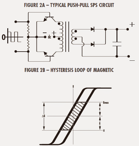
CORE IN PUSH-PULL CIRCUIT
For ferrite transformers, at 20 kHz, it is usually well-known process to employ equation (4) with a flux density (B) level of ±2 kG max.
This can be drawn out by the coloured section of the Hysteresis Loop in Figure 2B. This B degree is selected mainly because the restricting aspect of selecting a core with this frequency is core loss.
At 20 kHz, if the transformer is ideal for a flux density around saturation (as carried out for smaller frequency layouts), the core is going to acquire an uncontrolled temperature surge.
For that reason, the smaller operating flux density of 2 kG will in most cases confine the core losses, consequently helping an affordable temperature increase in the core.
Above 20 kHz, core losses maximize. To execute the SPS at raised frequencies, it is important to execute the core flux rates lesser than ±2 kg. Figure 3 exhibits the decline in flux levels for MAGNETICS “P” ferrite material vital for contributing constant 100mW/cm3 core losses at numerous frequencies, with a optimum temperature surge of 25°C.
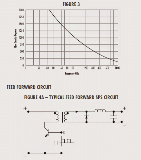
In the feed forward circuit laid out in Figure 4A, the transformer executes in the 1st quadrant of the Hysteresis Loop. (Fig 4B).
Unipolar pulses implemented to the semiconductor device bring about the transformer core to be powered from its BR value near saturation. As the pulses are downsized to zero, the core reverts to its BR rate.
To be able to keep up a superior efficiency, the primary inductance is maintained high to help reduce magnetizing current and lessen wire drawdowns. This implies the core needs to have a zero or a bare minimum of air flow opening.