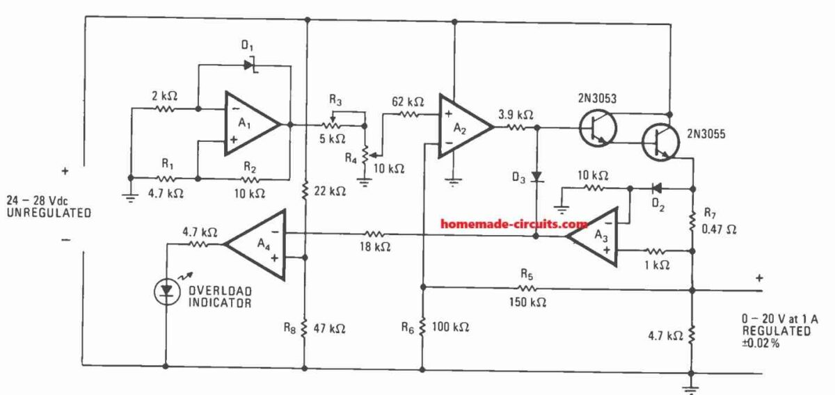
In this post I have explained how a single LM324 IC can be used to create an adjustable voltage regulator circuit with overload and over current protections.
Basic Working
A basic IC LM324 quad operational amplifier regulates an unregulated 28-volt input source to approximately ±0.02%, resulting in a 1 amp 0 to -20 V supply.
The quiescent current is below 10 mA, and the input voltage can fluctuate between 24 and 28 V. An overload indicator is provided by a light-emitting diode, and its level is determined by the resistance of resistor R8.
Due to the need for two separate voltage sources—one main and one reference—along with the related rectifiers, filter capacitors, and reference regulator circuitry, full-range, efficient power supplies are frequently large and costly.
However, a regulated power supply that delivers constant current 1 amp with an adjustable 0 to 20 volts with foldback current limiting and overload signaling only needs one unregulated source of around 26 volts dc and one ground-sensing LM324 quad operational amplifier.
Circuit Description


Regardless of load variations, this LM324 voltage regulator circuit is able to maintain line and load regulation within ±0.02%, even while the input voltage fluctuates between 24 and 28 v dc.
The regulator requires a maximum of 10 milliamperes of current while it is in a quiescent state.
The self-biased, constant-current amplifier indicated as Amplifier A1 generates a steady reference voltage.
The breakdown voltage Vz of the zener diode, D1, determines its reference voltage output, V1, which can be calculated using the following formula:
V1 = Vz[1 + (R1/R2)]
For the numbers displayed in the diagram, it is around 9.1 v.
After V1 is reduced to the desired level, we want feedback voltage V2, and this is then amplified by A2.
Subsequently, the Darlington output stage raises the output voltage to:
Vout = V2(R5 + R6)/R6
Variable resistor R3 sets the voltage at precisely 20 volts when R4 is at the highest possible voltage setting. R4 then adjusts the output voltage across its whole range.
The figures displayed indicate an output stage gain of 2.5.
While the load varies, amplifier A3 keeps an eye on the regulator's output current.
It does a comparison between the voltage across diode D2 and the extremely tiny resistance R7.
The output of A3 goes down each time the former is larger than the latter, biasing diode D3 forward and lowering the output voltage by cutting off the drive to the Darlington stage.
If the load keeps going up, the output of A3 drops to the point where amplifier A4 and a light-emitting diode may detect an overload problem.
If required, resistor R8's value can be altered to alter the circuit's overload tolerance.
The number of devices can be decreased from three to two by substituting the output transistors with a single power Darlington, such the 2N6050.
Parts List
- Resistors are 1/4 watt 5% CFR unless specified
- 2k, 22k, 18k, 47k, 100k, 150k, 3.9k, 1k = 1 each
- 4.7k = 3
- 0.47 ohms 2 watt = 1
- 5k preset = 1
- 10k pot = 1
- Semiconductors
- D1 zener diode = 9V 1/2 watt
- D2, D3 1N4148 = 2
- IC LM324 = 1
- Transistor 2N3053, 2N3055 = 1 each
- LED 20mA, 5mm = 1
Good evening Sir.
Thanks for the great work you are doing.
Sir, I need a circuit diagram for a digital voltmeter and ammeter module. That will not use programmable ics. But ics that are easy to find
Hi Ngang, I think you should try the following concept, however I am not sure whether the ICs are still available in the market or are obsolete.
https://www.homemade-circuits.com/how-to-make-digital-voltmeter-ammeter/
Swagatam bhai, I need your help. I have a Yamaha SRX600 for which I am trying to make a regulator/rectifier. its manufacturer suggests the following specification
Voltage Regulator/Rectifier:
Type Short Control,
model SH565 make Shindengen 14-15V
Capacity 12A withstand voltage 200V
Generator is VCD48/Nippon Denso 14.5V 11A at 5000 rpm
It is not available where I live. Perhaps this model is obsolete because this bike is 1986 model. Normal 2 phase and 3 phase RR units available locally do not work, recently I fried one.
It has 2 wires coming out of the stator, none of them is grounded. Both of these wires if connected directly gives current, alone they don’t conduct spark when touched the ground. Only when they are paired together makes it spark.
I tried one of the regulator circuit from your collection but it did work. So I thought I will ask you for your help.
looking forward to hearing from you
Irfan bhai,
Please check the voltage between the two connected wires and the ground. I guess it should be an AC.
If you find the voltage as per the desired level, you can then connect this voltage source to the first regulator circuit which is explained in the following article:
https://www.homemade-circuits.com/3-phase-motorcycle-voltage-regulator/
Let me know how it goes.