In this article I will explain how we can build an Arduino-controlled H-Bridge sine wave inverter circuit using some easy parts. So this thing will basically convert DC into AC but in a way that looks like a sine wave, right? We are using an Arduino to generate PWM signals and these signals will drive an H-Bridge circuit made using IR2110 MOSFET driver ICs and power MOSFETs. This setup will allow us to switch MOSFETs in a controlled manner and create an AC output from our DC supply.
Understanding the Circuit Design
If you don't want to read the whole explanation, you can watch this video instead:

Now let us see the circuit diagram below and learn how this thing is actually working. We see the following main parts in the circuit:
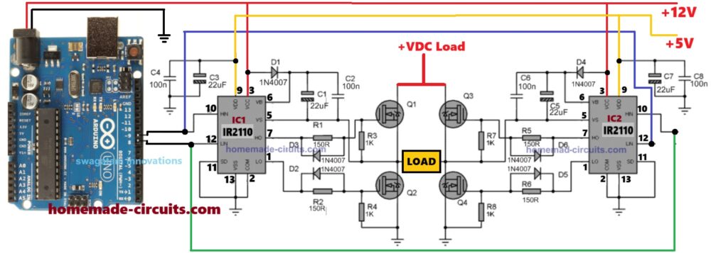
Arduino Board – This is our brain. It gives out SPWM pulses that decide how our circuit will run.
IR2110 MOSFET Driver ICs (IC1 and IC2) – These devices take the standard SPWM signals from Arduino and make them compatible to switch the 4 N-channel H-bridge MOSFETs properly, using bootstrapping method.
MOSFETs (Q1, Q2, Q3, Q4) – These are the power switches. They turn the DC power ON and OFF in a specific way to create AC at the output.
Diodes (1N4007) and capacitors – These are for enabling the correct working of the bootstrapping network of the ICs for perfect switching of the 4 MOSFETs.
Other Capacitors and Resistors – These are small but very important because they keep everything running smoothly.
Power Supply – We need +12V and +5V for Arduino and the IR2110 ICs, and a high DC voltage for the MOSFETs, as per the load specifications.
What is Happening in the Circuit?
Now let us see how this works step by step:
Arduino generates SPWM signals at two output pins (Pin 8 and Pin 9). These signals keep changing width to create a shape equivalent to a AC sine wave.
IR2110 ICs receive these PWM signals and use them to switch the MOSFETs ON and OFF in a very specific way.
The H-Bridge made using four MOSFETs converts the DC bus supply into AC-like output by switching the current direction through the load using the SPWM switching.
At the output we get a sine wave approximation which means it looks like a sine wave but is actually made of fast-switching pulses.
If we add a filter circuit at the output then we can smooth these pulses and get a more perfect sine wave.
Our Arduino Code for Sine Wave PWM
So now let us see the code. This is what the Arduino will run to generate the SPWM signals.
// By Swagatam
void setup() {
    pinMode(8, OUTPUT);
    pinMode(9, OUTPUT);
}

void loop() {
    // First half of the sine wave
    digitalWrite(8, HIGH);
    delayMicroseconds(500);
    digitalWrite(8, LOW);
    delayMicroseconds(500);

    digitalWrite(8, HIGH);
    delayMicroseconds(750);
    digitalWrite(8, LOW);
    delayMicroseconds(500);

    digitalWrite(8, HIGH);
    delayMicroseconds(1250);
    digitalWrite(8, LOW);
    delayMicroseconds(500);

    digitalWrite(8, HIGH);
    delayMicroseconds(2000);
    digitalWrite(8, LOW);
    delayMicroseconds(500);

    digitalWrite(8, HIGH);
    delayMicroseconds(1250);
    digitalWrite(8, LOW);
    delayMicroseconds(500);

    digitalWrite(8, HIGH);
    delayMicroseconds(750);
    digitalWrite(8, LOW);
    delayMicroseconds(500);

    digitalWrite(8, HIGH);
    delayMicroseconds(500);
    digitalWrite(8, LOW);

    // Second half of the sine wave
    digitalWrite(9, HIGH);
    delayMicroseconds(500);
    digitalWrite(9, LOW);
    delayMicroseconds(500);

    digitalWrite(9, HIGH);
    delayMicroseconds(750);
    digitalWrite(9, LOW);
    delayMicroseconds(500);

    digitalWrite(9, HIGH);
    delayMicroseconds(1250);
    digitalWrite(9, LOW);
    delayMicroseconds(500);

    digitalWrite(9, HIGH);
    delayMicroseconds(2000);
    digitalWrite(9, LOW);
    delayMicroseconds(500);

    digitalWrite(9, HIGH);
    delayMicroseconds(1250);
    digitalWrite(9, LOW);
    delayMicroseconds(500);

    digitalWrite(9, HIGH);
    delayMicroseconds(750);
    digitalWrite(9, LOW);
    delayMicroseconds(500);

    digitalWrite(9, HIGH);
    delayMicroseconds(500);
    digitalWrite(9, LOW);
}
What is Going On in This Code?
First we set up two output pins (Pin 8 and Pin 9). These will send out our PWM signals.
Then in the loop we turn the pin ON and OFF in a special pattern.
We start with narrow pulses and gradually increase the pulse width and then we reduce it back down. This creates a stepped sine wave PWM pattern.
After the first half cycle is done then we repeat the same thing on the other pin (Pin 9) for the next cycle.
This way our H-Bridge switches the MOSFETs in a proper sinusoidal wave like fashion.
What is Good about this Design
The design is actually very simple. We are using just an Arduino and some common components.
We do not need a sine wave generator here, right. The Arduino itself is making the sine shape using SPWM.
The H-Bridge works efficiently using the IR2110 ICs to make sure the MOSFETs switch correctly without overheating.
We can fine tune the SPWM easily, in case we want a different sine wave frequency, then we just modify the code a little.
How We Should Handle the Arduino Booting Delay
Now one very important thing that we must understand is that Arduino takes some time to start after we switch ON the power.
This happens because when we power ON the Arduino then it first runs its internal bootloader which takes a few seconds.
So during this time the IR2110 gate driver ICs and MOSFETs may not receive any proper signals from Arduino.
If that happens then the MOSFETs may turn ON randomly which can damage the ICs instantly, or cause a short circuit or explosion.
In order to make sure that the above booting delay does not burn the ICs and the MOSFETs during the initial power ON, we need to modify the above code as shown below:
// By Swagatam - Full Bridge Sine Wave Inverter Code with Delay

void setup() {
    pinMode(8, OUTPUT);
    pinMode(9, OUTPUT);

    delay(3000); // Booting delay (wait for 3 seconds before starting)
}

void loop() {
    // First pin (8) switching pattern
    digitalWrite(8, HIGH);
    delayMicroseconds(500);
    digitalWrite(8, LOW);
    delayMicroseconds(500);
    digitalWrite(8, HIGH);
    delayMicroseconds(750);
    digitalWrite(8, LOW);
    delayMicroseconds(500);
    digitalWrite(8, HIGH);
    delayMicroseconds(1250);
    digitalWrite(8, LOW);
    delayMicroseconds(500);
    digitalWrite(8, HIGH);
    delayMicroseconds(2000);
    digitalWrite(8, LOW);
    delayMicroseconds(500);
    digitalWrite(8, HIGH);
    delayMicroseconds(1250);
    digitalWrite(8, LOW);
    delayMicroseconds(500);
    digitalWrite(8, HIGH);
    delayMicroseconds(750);
    digitalWrite(8, LOW);
    delayMicroseconds(500);
    digitalWrite(8, HIGH);
    delayMicroseconds(500);
    digitalWrite(8, LOW);

    // Second pin (9) switching pattern
    digitalWrite(9, HIGH);
    delayMicroseconds(500);
    digitalWrite(9, LOW);
    delayMicroseconds(500);
    digitalWrite(9, HIGH);
    delayMicroseconds(750);
    digitalWrite(9, LOW);
    delayMicroseconds(500);
    digitalWrite(9, HIGH);
    delayMicroseconds(1250);
    digitalWrite(9, LOW);
    delayMicroseconds(500);
    digitalWrite(9, HIGH);
    delayMicroseconds(2000);
    digitalWrite(9, LOW);
    delayMicroseconds(500);
    digitalWrite(9, HIGH);
    delayMicroseconds(1250);
    digitalWrite(9, LOW);
    delayMicroseconds(500);
    digitalWrite(9, HIGH);
    delayMicroseconds(750);
    digitalWrite(9, LOW);
    delayMicroseconds(500);
    digitalWrite(9, HIGH);
    delayMicroseconds(500);
    digitalWrite(9, LOW);
}
Parts list
| Part | Specification | Quantity |
|---|---|---|
| Arduino Board | Arduino Uno (or any compatible board) | 1 |
| MOSFET Driver IC | IR2110 High & Low Side Driver | 2 |
| MOSFETs | IRF3205 (or similar N-channel) | 4 |
| Diodes | 1N4007 (for bootstrap & protection) | 4 |
| Resistors | 1KΩ 1/4W (MOSFET gate pull-down) | 4 |
| Resistors | 150Ω 1/4W (MOSFET gate series resistor) | 4 |
| Capacitors | 100nF (bootstrap capacitor) | 2 |
| Capacitors | 22uF 25V (power supply filter) | 2 |
| Load | Any resistive or inductive load | 1 |
| Power Supply | +12V DC (for MOSFETs) & +5V DC (for Arduino) | 1 |
| Wires & Connectors | Suitable for circuit connections | As needed |
Construction Tips
Now when we actually build this thing we have to be very careful about a few important things. Otherwise it may not work or worse, something may burn out right? So here are some super important construction tips that we must follow:
How We Should Arrange the Parts on the Board
If we use a breadboard then this circuit may not work well because high-power MOSFETs and drivers need strong, solid connections.
So we should use a PCB (Printed Circuit Board) or at least a perf board and solder the parts properly.
If we make a PCB then we must keep the MOSFETs and IR2110 ICs close together so that signals do not become weak or delayed.
The thick wires should go for high current paths like from the power supply to the MOSFETs and from the MOSFETs to the load.
The thin wires can be used only for signal connections like from Arduino to the IR2110 ICs.
How We Should Place the MOSFETs
The four MOSFETs should be placed in a proper H-Bridge shape so that the wiring does not become messy.
Each MOSFET should have short and thick connections to the IR2110 IC.
If we place the MOSFETs too far from the IR2110 then the signals may become weak and the MOSFETs may not switch properly.
If that happens then the MOSFETs can get hot and even burn out.
How We Should Fix the Heat Issue
If we use high current IRF3205 MOSFETs or similar ones, then they will heat up if we do not give them a heatsink.
So we must fix a big aluminum heatsink to the MOSFETs to keep them cool.
If we are making a high-power inverter (more than 1000 W) then we should also attach a cooling fan on the heatsink.
If the MOSFETs get too hot to touch then it means there is some issue and we need to check the circuit again.
How We Should Power the Circuit
The Arduino part runs on 5V and the MOSFETs need 12V or more to work.
So we must never connect 12V to Arduino, or it will burn instantly!
The IR2110 ICs need two power supplies:
12V for the high-side MOSFETs
5V for the logic section
If we mix up these power lines then the circuit will not work properly and the MOSFETs will not switch correctly.
How We Should Connect the Wires
The ground (GND) connection is super important. If the ground wiring is weak or long, then the circuit may behave weirdly.
We should use a common ground for all parts, meaning the Arduino ground, IR2110 ground and MOSFET source ground must be connected together.
If we see the circuit behaving strangely (like the output flickering or MOSFETs getting warm without a load), then we should check the ground connections first.
How We Should Check the Circuit Before Powering It Up
Before we switch ON the power we must double-check all connections to see if everything is correct.
If we have a multimeter then we should use it to check the voltages at different points before inserting the MOSFETs.
We will strictly need an oscilloscope so that we can check the SPWM signals coming from Arduino to see if they look correct.
How We Should Test the Circuit Carefully
The best way to test this circuit safely is by starting with a low voltage.
Instead of 12V we can first try with 6V or 9V to see if the MOSFETs are switching correctly.
If the circuit works well at low voltage then we can slowly increase to 12V and finally to the full voltage.
If we suddenly apply full voltage and something is wrong then something may burn out instantly!
So we must test step by step and keep checking for overheating or wrong behavior.
How We Can Add a Filter for a Smoother Output
This circuit makes an AC output using PWM but it is still made of fast pulses.
If we want a clean sine wave then we must add an LC filter at the output.
This LC filter is just a big inductor and a capacitor connected to the output.
The inductor removes the fast switching pulses and the capacitor smooths out the waveform.
If we do this properly then we can get a pure sine wave that is safe for appliances.
How We Should Protect the Circuit from Damage
We should always add a fuse in series with the power supply.
If something shorts or a MOSFET fails then the fuse will break first and save the circuit from burning.
If the MOSFETs fail then sometimes they fail shorted (meaning they always stay ON).
If that happens then huge current can flow and damage the transformer or other parts.
So it is always good to check the MOSFETs using a multimeter before applying high power.
Conclusion
So here we saw how we can make a sine wave inverter using just Arduino and an H-Bridge MOSFET circuit. We used IR2110 MOSFET drivers to properly switch the MOSFETs and PWM control from Arduino to generate our sine-modulated AC.
Now one thing to remember is that this output is still made of fast-switching pulses so if we need a pure sine wave then we must add a LC filter at the output to smooth it out.
But overall this is a very practical and easy way to make a sine wave inverter at home!
The delay in the program does not mean anything because the program is executed after the bootloader. It is better to put some pullup or pulldown resistors. It’s even better to tie the SD pin to a pullup resistor, and later at the beginning of the program pull it down with arduino.
Hello, I’m Jun Balista from the Philippines.
How come you did not mention the load voltage output anywhere in your article? It’s not even shown in your circuit diagrams. And the DC supply to the H-bridge was omitted, too! You should include both of them in the your next update perhaps? I believe those are very important things that you missed, sir.
Thanks.
Balista, I did not miss them, I did not mention them because they are not fixed values, and depends on the user application needs.
The LOAD voltage output will depend on the +VDC across the MOSFET drains, which can be any desired value depending on the load specifications.
how do you calculate the L and C values for the circuit? for the lc filter
Just add a 3uF/400V capacitor at the output AC side of the H-bridge, that’s all is needed for smoothing the output AC into an almost pure sine wave.
Thank you very much for your quick reply , yes I understand but I meant that the circuit is the same in all aspects but without arduino ….
Sure, no problem! To get a reasonably ok sine wave output without using Arduino, you can replace the Arduino with the following circuit: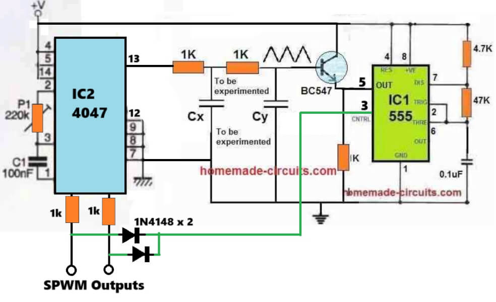
" rel="ugc">
This circuit comes in handy since I have a 220vac toroidal transformer at 12 x 8A with no center tap. Then I would like to assemble it. But as I am not with arduino, I want to know if you can replace the arduino by another circuit? Thank you very much.
Sure, you can just remove the Arduino and replace it with any standard astable oscillator such as using IC 4047, or a BJT astable, or an 555, opamp, CMOS IC based astable oscillator etc….but in that case the output will be a square wave AC output….