This article explains a simple pure sine wave inverter circuit using Arduino, which could be upgraded to achieve any desired power output as per the user's preference
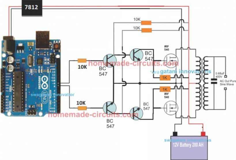
Circuit Operation
In the last article I have explained how to generate sine wave pulse width modulation or SPWM though Arduino, we are going to use the same Arduino board to make the proposed simple pure sine wave inverter circuit.The design is actually extremely straightforward, as shown in the following figure.
You just have to program the arduino board with the SPWM code as explained in the previous article, and hook it up with some of the external devices.
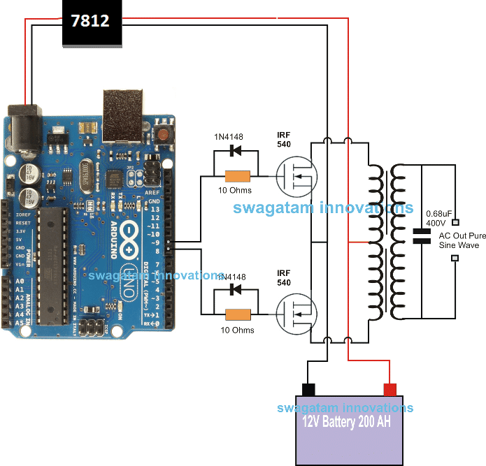
Pin#8 and pin#9 generate the SPWMs alternately and switch the relevant mosfets with the same SPWM pattern.
The mosfst in turn induce the transformer with high current SPWM waveform using the battery power, causing the secondary of the trafo to generate an identical waveform but at the mains AC level.
The proposed Arduino inverter circuit could be upgraded to any preferred higher wattage level, simply by upgrading the mosfets and the trafo rating accordingly, alternatively you can also convert this into a full bridge or an H-bridge sine wave inverter
Powering the Arduino Board
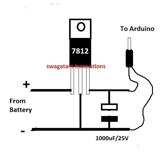
In the diagram the Arduino board could be seen supplied from a 7812 IC circuit, this could be built by wiring a standard 7812 IC in the following manner. The IC will ensure that the input to the Arduino never exceeds the 12V mark, although this might not be absolutely critical, unless the battery is rated over 18V.
If you have any questions regarding the above SPWM inverter circuit using a programmed Arduino, please feel free to ask them through your valuable comments.
Waveform Images for Arduino SPWM
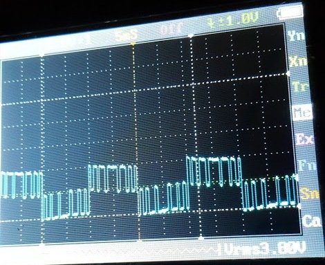
Image of SPWM waveform as obtained from the above Arduino inverter design (Tested and Submitted By Mr. Ainsworth Lynch)
UPDATE:
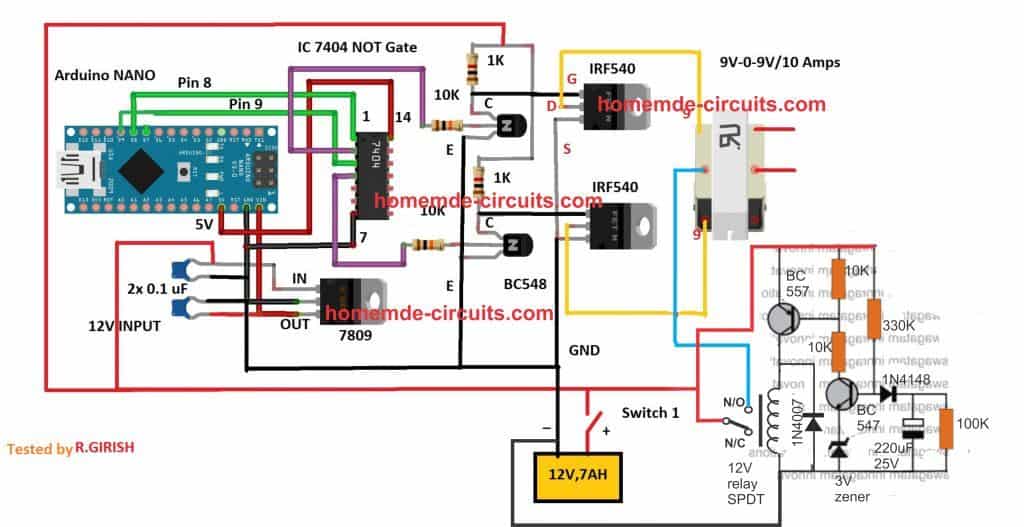
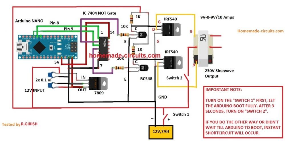
Using BJT Buffer Stage as Level Shifter
Since an Arduino board will produce a 5V output, it may not be an ideal value for driving mosfets directly.
Therefore an intermediate BJT level shifter stage may be required for raising the gate level to 12V so that the mosfets are able to operate correctly without causing unnecessary heating up of the devices,. The updated diagram (recommended) can be witnessed below:

For the full Program Code please visit the following link: Arduino SPWM Generator Circuit
Video Clip

Parts List
All resistors are 1/4 watt, 5% CFR
- 10K = 4
- 1K = 2
- BC547 = 4nos
- Mosfets IRF540 = 2nos
- Arduino UNO = 1
- Transformer = 9-0-9V/220V/120V current as per requirement.
- Battery = 12V, Ah value as per requirement
Delay Effect
To ensure that the mosfet stages initiate with a delay during the Arduino booting or start up, you may modify left side BC547 transistors into delay ON stages, as shown below. This will safeguard the mosfets and prevent them from burning during power switch ON Arduino booting.

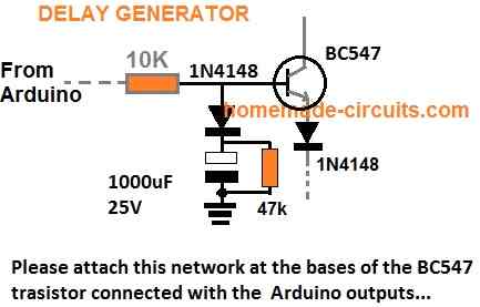
FOR INCREASING THE DELAY YOU CAN INCREASE THE 10K VALUE TO 100K
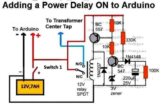
A More Reliable Delay ON Timer
If you are not comfortable with the response of the above passive delay ON timer circuit, you can employ the following configuration using BJTs and a relay. This design is extremely reliable and will effectively protect your Arduino and the inverter from burning due to a malfunctioning delay effect.
Just add this to the above inverter configuration.

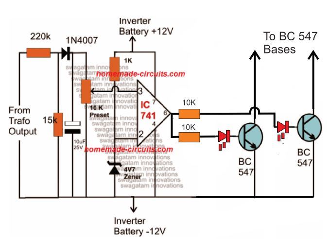
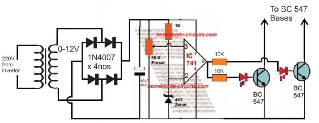
Adding an Automatic Voltage Regulator
Just like any other inverter the output from this design can rise to unsafe limits when the battery is fully charged.
To control this an automatic voltage regulator could be employed as shown below.
The BC547 collectors should be connected to the bases of the left side BC547 pair, which are connected to the Arduino via 10K resistors.

For an isolated version of voltage correction circuit we can modify the above circuit with a transformer, as shown below:

How to Setup
To set up the automatic voltage correction circuit, feed a stable 230V or 110V as per your inverter specs to the input side of the circuit.
Next, adjust the 10k preset carefully such that the red LEDs just light up. That's all, seal the preset and connect the circuit with the above Arduino board for implementing the intended automatic output voltage regulation.
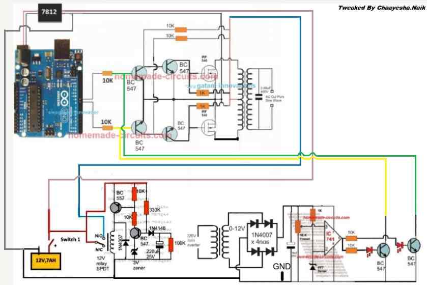
The Complete Circuit Diagram
The complete diagram using the automatic voltage regulator and the delay ON timer would look like this:

Using CMOS Buffer
Another design for the above Arduino sinewave inverter circuit can be seen below, the CMOS IC is used as an aided buffer for the BJT stage

Important:
In order to avoid an accidental switch ON prior to Arduino booting, a simple delay ON timer circuit may be included in the above design, as shown below: