In this post I have explained how to control servo motors using a joystick and Arduino. We will see overview about joystick, its pins, its construction and working. We will be extracting useful data from the joy stick which will be base for controlling the servo motors.
Introduction
The motto of this article is not just to control the servo motors but, to learn how to use a joystick for controlling many other peripheral devices.
Now let’s take a look at the joystick.
A joystick is an input device which consists of a lever, which can move in several directions in X and Y axes. The movement of the lever is used for controlling a motor or any peripherals electronic devices.
Joysticks are used from RC toys to Boing airplanes and perform similar functions. Additionally gaming and smaller joy sticks have a push button in Z axis which can be programmed to do many useful actions.
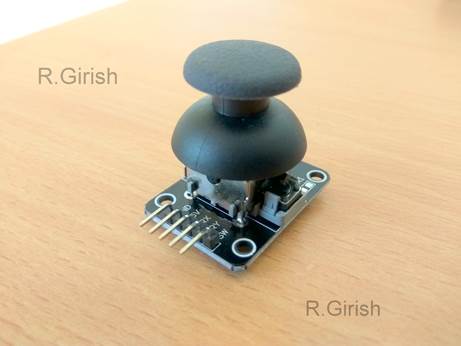
Illustration of Joystick:
Joysticks are electronic devices in general so, we need to apply power. The movement of the lever produces voltage difference at output pins. The voltage levels are processed by a microcontroller to control the output device such as a motor.
The illustrated joystick is similar one, which can be found in PlayStation and Xbox controllers. You no need to break these controllers to salvage one. These modules are readily available at local electronic shops and E-commerce sites.
Now let’s see the construction of this joystick.
It has two 10 Kilo ohm potentiometer positioned in X and Y axes with springs so that, it returns to its original position when the user release force from the lever. It has a push to ON button on Z axis.
It has 5 pins, 5 volt Vcc, GND, variable X, variable Y, and SW (Z axis switch). When we apply voltage and left the joystick on its original lever position. The X and Y pins will produce half of the applied voltage.
When we move the lever the voltage varies in X and Y output pins. Now let’s practically interface the joystick to Arduino.
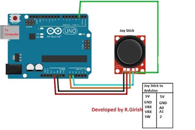
Schematic Diagram:
The pin connection details are given beside the circuit. Connect the completed hardware setup and upload the code.
Program:
//---------------Program Developed by R.Girish--------------//

int X_axis = A0;

int Y_axis = A1;

int Z_axis = 2;

int x = 0;

int y = 0;

int z = 0;

void setup()

{

Serial.begin(9600);

pinMode(X_axis, INPUT);

pinMode(Y_axis, INPUT);

pinMode(Z_axis, INPUT);

digitalWrite(Z_axis, HIGH);

}

void loop()

{

x = analogRead(X_axis);

y = analogRead(Y_axis);

z = digitalRead(Z_axis);

Serial.print("X axis = ");

Serial.println(x);

Serial.print("Y axis = ");

Serial.println(y);

Serial.print("Z axis = ");

if(z == HIGH)

{

Serial.println("Button not Pressed");

}

else

{

Serial.println("Button Pressed");

}

Serial.println("----------------------------");

delay(500);

}

//---------------Program Developed by R.Girish--------------//
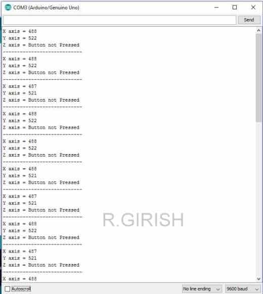
Open the Serial monitor you can see the voltage level at the X and Y axes pins and the status of the Z axis i.e. push button as illustrated below.
These X, Y, Z axes values are used to interpret the position of the lever. As you can see the values are from 0 to 1023.
That’s because Arduino has built in ADC converter which convert the voltage 0V - 5V to 0 to 1023 values.
You can witness from the serial monitor that when the lever is left untouched the lever stays at mid position of both X and Y axes and shows half value of 1023.
You can also see it is not exact half of the 1023 that’s because manufacturing these joysticks never been perfect.
By now, you would have got some technical knowledge about joysticks.
Now let’s see how to control two servo motors using one joystick.
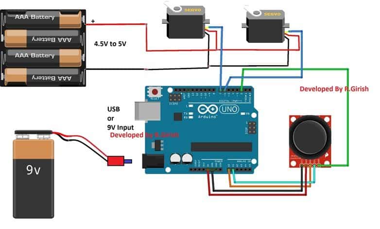
Circuit Diagram:

The two servo motors are controlled by one joystick; when you move the joystick along the X axis the servo connected at pin #7 moves Clockwise and Anti-clock wise depending on the lever position.
You can also hold the servo actuator at a position, if you hold the joystick level at a particular position.
Similar for servo motor connected at pin #6, you can move the lever along Y axis.
When you press the lever along the Z axis, the two motors will perform 180 degree sweep.
You can either connect the arduino to 9v battery or to computer. If you connect the Arduino to computer you can open serial monitor and see the angle of the servo actuators and voltage levels.
Program for servo motor control:
//---------------Program Developed by R.Girish--------------//

#include<Servo.h>

Servo servo_X;

Servo servo_Y;

int X_angleValue = 0;

int Y_angleValue = 0;

int X_axis = A0;

int Y_axis = A1;

int Z_axis = 2;

int x = 0;

int y = 0;

int z = 0;

int pos = 0;

int check1 = 0;

int check2 = 0;

int threshold = 10;

void setup()

{

Serial.begin(9600);

servo_X.attach(7);

servo_Y.attach(6);

pinMode(X_axis, INPUT);

pinMode(Y_axis, INPUT);

pinMode(Z_axis, INPUT);

digitalWrite(Z_axis, HIGH);

}

void loop()

{

x = analogRead(X_axis);

y = analogRead(Y_axis);

z = digitalRead(Z_axis);

if(z == LOW)

{

Serial.print("Z axis status = ");

Serial.println("Button Pressed");

Serial.println("Sweeping servo actuators");

for (pos = 0; pos <= 180; pos += 1)

{

servo_X.write(pos);

delay(10);

}

for (pos = 180; pos >= 0; pos -= 1)

{

servo_X.write(pos);

delay(15);

}

for (pos = 0; pos <= 180; pos += 1)

{

servo_Y.write(pos);

delay(10);

}

for (pos = 180; pos >= 0; pos -= 1)

{

servo_Y.write(pos);

delay(15);

}

Serial.println("Done!!!");

}

if(x > check1 + threshold || x < check1 - threshold)

{

X_angleValue = map(x, 0, 1023, 0, 180);

servo_X.write(X_angleValue);

check1 = x;

Serial.print("X axis voltage level = ");

Serial.println(x);

Serial.print("X axis servo motor angle = ");

Serial.print(X_angleValue);

Serial.println(" degree");

Serial.println("------------------------------------------");

}

if(y > check2 + threshold || y < check2 - threshold)

{

Y_angleValue = map(y, 0, 1023, 0, 180);

servo_Y.write(Y_angleValue);

check2 = y;

Serial.print("Y axis voltage level = ");

Serial.println(y);

Serial.print("Y axis servo motor angle = ");

Serial.print(Y_angleValue);

Serial.println(" degree");

Serial.println("------------------------------------------");

}

}

//---------------Program Developed by R.Girish--------------//
If you have any specific question regarding this project, feel free to express in the comment section, you may receive a quick reply.


Hi swagatam, Is there any one can modify the joystick to a gimbal?
Hi Miebaka, I am not sure about it, will need to investigate it..
Should not the 2 servos be connected to PWM pins?
Hi,
You can connect, if you want same arm moments from those two motors.
You can’t connect, if you want independent arm control from the two motors.
You can connect servo motors to non-PWM pins also.
Regards
thnx