In this post I will show how to construct a stopwatch which automatically starts timer when the runner begins to run and the timer stops when the runner reaches the end. The elapsed time between starting and ending point is displayed on a 16 x 2 LCD.
First let's begin by learning how to configure a simple and extremely accurate Arduino stop watch circuit.
A stopwatch is a manually controlled time clock device designed for measuring the length of time that may have elapsed starting from a particular point of time when it was activated, and by the time it was finally deactivated.A bigger variant of the same device is called the stop clock which is used for monitoring the action from a distance and is normally found in sports stadium etc.
Mechanical vs Electronic Stopwatch
Earlier the traditional mechanical handheld stopwatch were more common, and used by all for the purpose.
In the mechanical system we had two press buttons for executing the stop watch functions. One for starting the stop clock by pressing once, and for stopping the time by pressing the same button once again for recording the elapsed time....the second button was used for resetting the clock back to zero.
Mechanical stop clock basically worked through spring power, which required period winding up manually by turning the given knurled knob at the top of the clock device.
However compared to the modern digital stop watches, the mechanical types can be considered significantly primitive and inaccurate in the range of milliseconds.
Using an Arduino
And today with the advent of microcontroller, these stop watches have become extremely accurate and reliable to the microsecond range.
Arduino stop watch circuit presented here is one of these modern microcontroller powered design which is most accurate can be expected to be on par with the commercial modern stop watch gadgets.
I have explained how to build the proposed Arduino stop clock circuit:
You will need the following Bill of materials for the construction:
Hardware Required
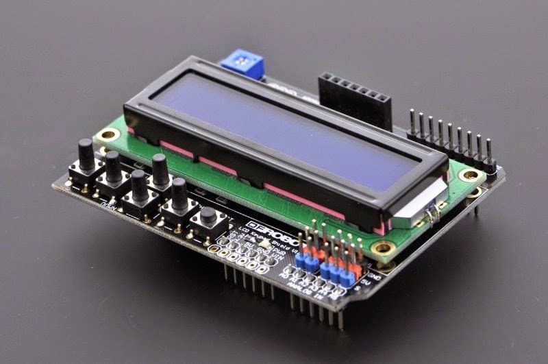
An Arduino LCD KeyPad Shield (SKU: DFR0009)

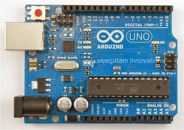
An Arduino UNO board
An Arduino USB cable
Once you have acquired the above material and hooked them up with each other, it's just about configuring the following given sketch code into your Arduino board and watch the magic of the stop clock functions.
The Code
/*

Standalone Arduino StopWatch

By Conor M - 11/05/15

Modified by Elac - 12/05/15

*/

// call the necessary libraries

#include <SPI.h>

#include <LiquidCrystal.h>

// these are the pins used on the shield for this sketch

LiquidCrystal lcd(8, 13, 9, 4, 5, 6, 7);

// variables used on more than 1 function need to be declared here

unsigned long start, finished, elapsed;

boolean r = false;

// Variables for button debounce time

long lastButtonPressTime = 0; // the last time the button was pressed

long debounceDelay = 50; // the debounce time; keep this as low as possible

void setup()

{

lcd.begin(16, 2); // inicialize the lcd (16 chars, 2 lines)

// a little introduction :)

lcd.setCursor(4, 0); // set the cursor to first character on line 1 - NOT needed (it sets automatically on lcd.begin()

lcd.print("Arduino");

lcd.setCursor(3, 1); // set the cursor to 4th character on line 2

lcd.print("StopWatch");

delay(2000); // wait 2 seconds

lcd.clear(); // clear the display

lcd.print("Press select for");

lcd.setCursor(2, 1); // set the cursor to 3rd character on line 2

lcd.print("Start & Stop");

}

void loop()

{

CheckStartStop();

DisplayResult();

}

void CheckStartStop()

{

int x = analogRead (0); // assign 'x' to the Arduino's AnalogueInputs (Shield's buttons)

if (x < 800 && x > 600 ) // if the button is SELECT

{

if ((millis() - lastButtonPressTime) > debounceDelay)

{

if (r == false)

{

lcd.clear();

lcd.setCursor(2, 0); // needed

lcd.print("Elapsed Time");

start = millis(); // saves start time to calculate the elapsed time

}

else if (r == true)

{

lcd.setCursor(2, 0); // needed

lcd.print(" Final Time ");

}

r = !r;

}

lastButtonPressTime = millis();

}

}

void DisplayResult()

{

if (r == true)

{

finished = millis(); // saves stop time to calculate the elapsed time

// declare variables

float h, m, s, ms;

unsigned long over;

// MATH time!!!

elapsed = finished - start;

h = int(elapsed / 3600000);

over = elapsed % 3600000;

m = int(over / 60000);

over = over % 60000;

s = int(over / 1000);

ms = over % 1000;

// display the results

lcd.setCursor(0, 1);

lcd.print(h, 0); // display variable 'h' - the 0 after it is the

number of algorithms after a comma (ex: lcd.print(h, 2); would print

0,00

lcd.print("h "); // and the letter 'h' after it

lcd.print(m, 0);

lcd.print("m ");

lcd.print(s, 0);

lcd.print("s ");

if (h < 10)

{

lcd.print(ms, 0);

lcd.print("ms ");

}

}

}
Adding a 7 Segment Display
Now let's proceed with the details regarding construction of a stopwatch circuit using 7 segment LED display and Arduino. We will be exploring the concepts related to interrupts and display driver ICs which are crucial for understand this project. This project was suggested by Mr Abu-Hafss who is one of the avid reader of this website.
As we already know that Stopwatch is a device which helps to track brief period of time from hours to milliseconds range (mostly). Almost all cheap digital wrist watches equipped with stopwatch functionality, but none of the watches can give the zest of making one for our self and also finding a stopwatch with 7 segment LED display is exceptional.
Mr Abu-Hafss suggested us to design a stopwatch with 4 displays, two for minutes and two for seconds (MM:SS) configuration. But for most of us it may not be a feasible design, so we added two more display for millisecond range so now the proposed design will be in MM:SS:mS configuration.
If you just need MM:SS configuration for some reason, you no need to connect the millisecond range 7 segment displays and its driver ICs, the whole functionality of the circuit still be unaffected.
The circuit:
The proposed stopwatch consists of six IC 4026 which is seven segment display driver, six 7 segment LED displays, one Arduino board, a couple of push buttons and couple of 10K resistors.
Now let’s understand how to connect IC 4026 to 7 segment display.
The 7 segment display can be any common cathode display of any colour. The 7 segment display can get easily killed by 5V supply, so a 330 ohm resistor is mandatory on each segment of the display.
Now let’s see the pin diagram of IC 4026:
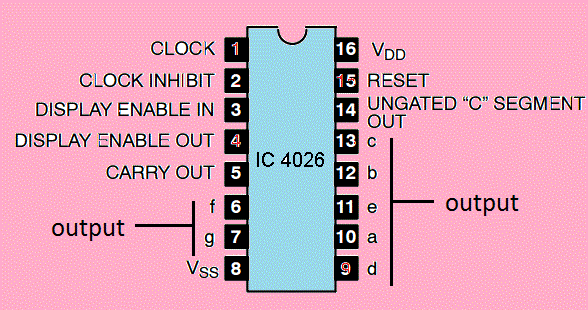
- The pin #1 is clock input.
- The pin #2 is clock disable, it disable the count on display if this pin is high.
- The pin #3 is display enable; if this pin is low the display will be tuned off and vice versa.
- The pin #5 is carry-out, which becomes high when IC counts 10.
- The pins 6, 7, 9, 10, 11, 12, 13 are display outputs.
- The pin #8 is GND.
- The pin #16 is Vcc.
- The pin #15 is reset, if we high this pin the count turns to zero.
- The pins #4 and #14 are not used.
Display connection diagram:
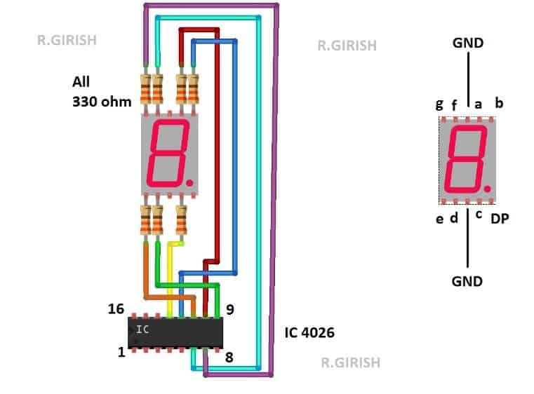
Any one of the GND pin of 7 segment display can be connected to ground. The IC must be powered from 5V supply or Arduino’s 5V output pin.
The above schematic for just one display, repeat the same for five other displays.
Here is the rest of the schematic:
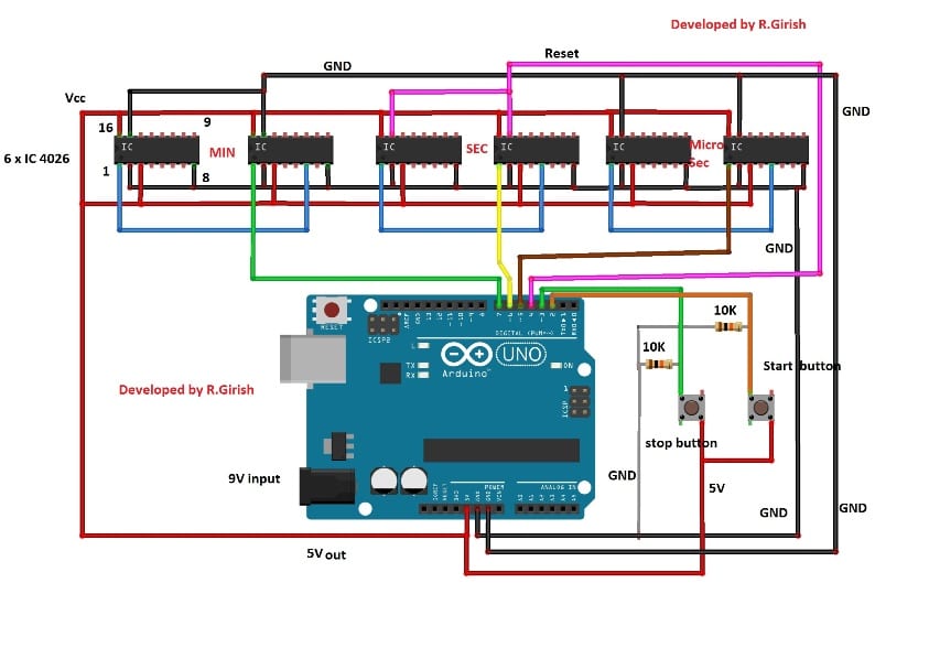
The circuit may be powered from 9V battery. The are two buttons provided here one for starting the time and another for stopping. By pressing reset button on Arduino, the time count will be reset to zero on display.
The two push button are connected to pin #2 and #3 which are hardware interrupt of Arduino / Atmega328P microcontroller.
Let’s understand what interrupt is:
There are two types of interrupts: hardware interrupt and software interrupt. Here we are using only the hardware interrupt.
An interrupt is a signal to the microcontroller, which will makes the microcontroller to respond immediately to an event.
There are only two hardware interrupt pins in Arduino boards with ATmega328P microcontroller; pin #2 and #3. Arduino mega has more than two hardware interrupt pins.
The microcontrollers can’t do two functions at same time. For example checking for button press and counting numbers.
The microcontrollers cannot execute two events simultaneously, if we write a code for checking button press and counting numbers, the button press will get detected only when the microcontroller reads the button press detection piece of code, rest of the time (counts the numbers) the button doesn’t work.
So there will be delay in detection of the button press and for some reason if the code gets halted temporarily, the button press may never get detected. To avoid these kinds of issues interrupt is introduced.
The interrupt signal is always given highest priority, the main function (main lines of code) will be halted and executes the (another piece of code) function assigned for that particular interrupt.
This is very important for time critical applications like stopwatch or security systems etc. where the processor need to take immediate action in response to an event.
In Arduino we assign hardware interrupt as:
attachInterrupt(0, start, RISING);
- “0” means the interrupt number zero (in microcontrollers everything starts from zero) which is pin#2.
- “start” is name of the interrupt function, you can name anything here.
- “RISING” if the pin #2 (which is interrupt zero) goes high, the interrupt function executes.
attachInterrupt(1, Stop, RISING);
- “1” means the interrupt number one which is pin #3.
- “Stop” is name of the interrupt.
We can also replace “RISING” with “FALLING”, now when the interrupt pin goes LOW the interrupt function executes.
We can also replace “RISING” with “CHANGE”, now whenever the interrupt pin goes from high to low or low to high, the interrupt function executes.
The interrupt function can be assigned as follows:
void start() //start is the name of the interrupt.
{
//program here
}
The interrupt function must be short as possible and delay() function cannot be used.
That concludes the hardware interrupt; software interrupt related to Arduino will be explained in future article.
Now you know why we connected the start and stop push buttons to interrupt pins.
Connect the circuit as per the diagram; rest of the circuit is self-explanatory.
Program:
//----------------Program Developed by R.GIRISH---------------//

int vmin = 0;

int vsec = 0;

int vms = 0;

boolean Run = false;

const int Min = 7;

const int sec = 6;

const int ms = 5;

const int reset_pin = 4;

void setup()

{

pinMode(Min, OUTPUT);

pinMode(sec, OUTPUT);

pinMode(ms, OUTPUT);

pinMode(reset_pin, OUTPUT);

digitalWrite(Min, LOW);

digitalWrite(sec, LOW);

digitalWrite(ms, LOW);

digitalWrite(reset_pin, HIGH);

digitalWrite(reset_pin, LOW);

attachInterrupt(0, start, RISING);

attachInterrupt(1, Stop, RISING);

}

void loop()

{

if (Run)

{

vms = vms + 1;

digitalWrite(ms, HIGH);

delay(5);

digitalWrite(ms, LOW);

delay(5);

if (vms == 100)

{

vsec = vsec + 1;

digitalWrite(sec, HIGH);

digitalWrite(sec, LOW);

vms = 0;

}

if (vsec == 60)

{

vmin = vmin + 1;

digitalWrite(Min, HIGH);

digitalWrite(Min, LOW);

digitalWrite(reset_pin, HIGH);

digitalWrite(reset_pin, LOW);

vsec = 0;

}

}

}

void start()

{

Run = true;

}

void Stop()

{

Run = false;

}

//----------------Program Developed by R.GIRISH---------------//
Now that concludes the code.
Stopwatch Specially Developed for the Atheletes
Finally, I have explained how the above concepts cam be actually upgraded for athletes who wish to develop their running skills without depending on others for the necessary start and stop the timer/stopwatch. It is better to automatically start the timer by detect your motion than someone starting/stopping the stopwatch, which might add their reaction time too.
NOTE: This project is designed for measuring the time between point ‘A’ to point ‘B’ covered by ONE user at a time.
The setup consists of two lasers placed at starting point and ending point, two LDRs is also placed opposite to two laser module. When the athlete interrupts the ‘starting’ laser the time begin to calculate and when the athlete reaches the end, interrupts ‘ending’ laser and timer stops and displays the elapsed time between two points. This is the method used to measure the elapsed time in the proposed idea.
Let’s look each and every component of the circuit in detail.
Components Working Details
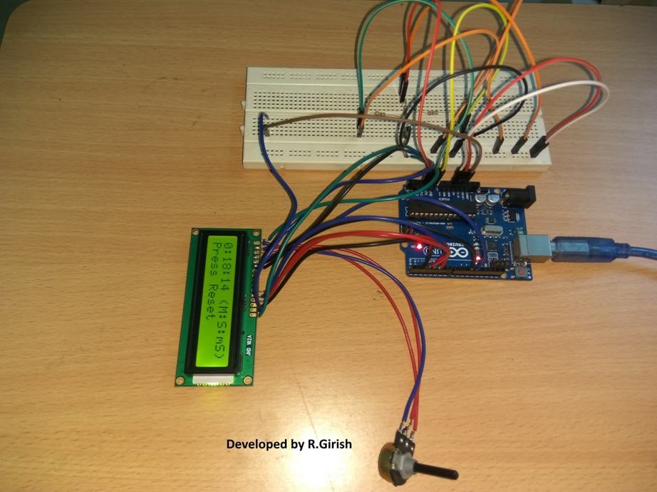
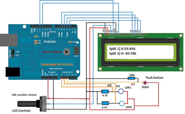
The circuit is kept fairly simple, it consists of 16 x 2 LCD module, few resistors, two LDRs and a push button.
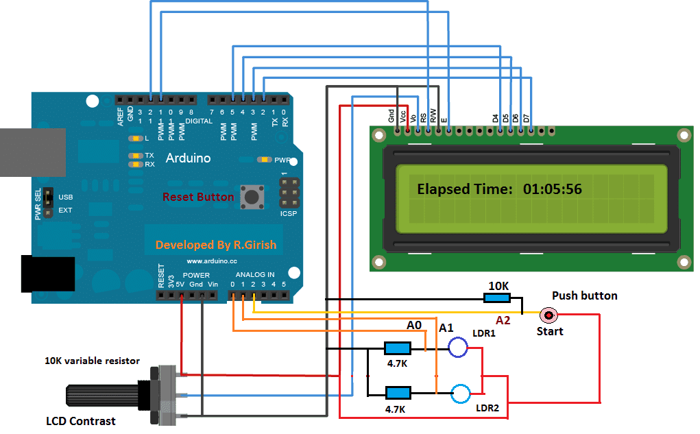
The interface between LCD and arduino is standard; we can find similar connection in many other LCD based projects.
Two analogue pins A0 and A1 are used to detect laser interruptions. Analogue pin A2 is connected with push button which is used to arm the stopwatch.
Three resistors, two 4.7K and one 10K are pull-down down resistors which helps input pins to stay at low.
10K potentiometer is provided for adjusting contrast in LCD module for optimal visibility.
The proposed circuit has designed with fault detection mechanism for lasers. If any one of the laser is fault or not aligned properly with LDR, it displays an error message on LCD display.
· If START laser is not functioning, it displays “ ‘start’ laser is not working”
· If STOP laser is not functioning, it displays “ ‘stop’ laser is not working”
· If both the lasers are not functioning, it displays “Both lasers are not working”
· If both the lasers are functioning properly, it displays “Both lasers are working fine”
The error message appears until the laser module fixed or alignment is done properly with LDR.
Once this step is free of problem, the system goes to standby mode and displays “-system standby-“. At this point the user can arm the setup by pressing the push button any time.
One the push button is pressed the system is ready to detect motion from the user and displays “System is ready”.
The runner may be few inches from the ‘start’ laser.
If the “start” laser is interrupted the time begins to count and the displays” Time is being calculated……” The time is calculated in the back ground.
The elapsed time won’t be displayed until the runner reaches/interrupts the “stop” laser. This is because displaying the elapsing time on LCD as traditional stopwatch does, require several additional instructions to be executed in the microcontroller, which deteriorates the accuracy of the setup significantly.
NOTE: Press reset button on arduino to clear the readings.
How to set the circuit on running track:
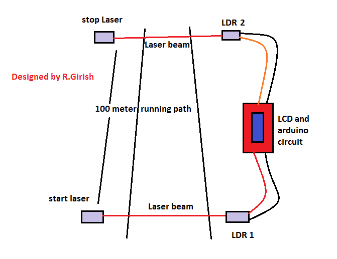
Please use thick wires to connect between LDRs and arduino circuit as the distance between these two may be several meters apart, and voltage must not drop significantly. The distance between LDR1 and LDR2 can be few hundred meters maximum.
How to mount LDR:
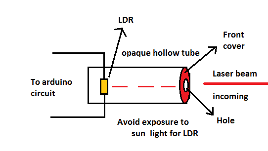
The LDR must be mounted inside hollow opaque tube and front part must also be covered and only a hole with few millimetres in diameter is made for allowing laser beam to enter in.
The LDR must be protected from direct sunlight as it cannot differentiate from laser beam and other source of light and might not register motion from the user.
Program Code:
//-------- Program developed by R.GIRISH-------//

#include <LiquidCrystal.h>

LiquidCrystal lcd(12,11,5,4,3,2);

int strt = A0;

int stp = A1;

int btn = A2;

int M = 0;

int S = 0;

int mS = 0;

float dly = 10.0;

void setup()

{

lcd.begin(16,2);

pinMode(strt,INPUT);

pinMode(stp,INPUT);

pinMode(btn,INPUT);

}

void loop()

{

if(digitalRead(strt)==HIGH && digitalRead(stp)==HIGH)

{

lcd.setCursor(0,0);

lcd.print("Both lasers are");

lcd.setCursor(0,1);

lcd.print(" working fine");

delay(4000);

{

while(digitalRead(btn)==LOW)

{

lcd.clear();

lcd.print("-System Standby-");

lcd.setCursor(0,1);

lcd.print("Press Start btn");

delay(100);

}

lcd.clear();

lcd.setCursor(0,0);

lcd.print("System is ready");

lcd.setCursor(0,1);

lcd.print("----------------");

while(digitalRead(strt)==HIGH)

{

delay(1);

}

lcd.clear();

lcd.setCursor(0,0);

lcd.print("Time is being");

lcd.setCursor(0,1);

lcd.print("Calculated......");

while(digitalRead(stp)==HIGH)

{

delay(dly);

mS = mS+1;

if(mS==100)

{

mS=0;

S = S+1;

}

if(S==60)

{

S=0;

M = M+1;

}

}

while(true)

{

lcd.clear();

lcd.setCursor(0,0);

lcd.print(M);

lcd.print(":");

lcd.print(S);

lcd.print(":");

lcd.print(mS);

lcd.print(" (M:S:mS)");

lcd.setCursor(0,1);

lcd.print("Press Reset");

delay(1000);

}

}

}

if(digitalRead(strt)==HIGH && digitalRead(stp)==LOW)

{

lcd.setCursor(0,0);

lcd.print("'Stop' laser is");

lcd.setCursor(0,1);

lcd.print(" not working");

delay(100);

}

if(digitalRead(strt)==LOW && digitalRead(stp)==HIGH)

{

lcd.setCursor(0,0);

lcd.print("'Start' laser is");

lcd.setCursor(0,1);

lcd.print(" not working");

delay(100);

}

if(digitalRead(strt)==LOW && digitalRead(stp)==LOW)

{

lcd.setCursor(0,0);

lcd.print("Both lasers are");

lcd.setCursor(0,1);

lcd.print(" not working");

delay(100);

}

lcd.clear();

}

//-------- Program developed by R.GIRISH-------//
Author’s prototype:
Upgrading with a Split Timer Facility
The proposed automatic stopwatch circuit with split timer is an extension of Automatic Stopwatch circuit, where the stopwatch tracks the time automatically as soon as the solo runner leaves the start point and the timer stops and show the elapsed time as runner reaches the end point.
Introduction
This project was suggested by one of the avid readers of this website Mr Andrew Walker.
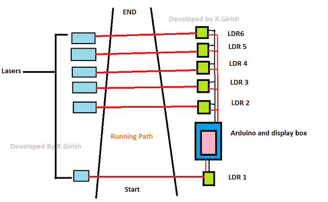
In this project we are introducing 4 more LDRs to measure the split time of the solo runner. There are 6 LDRs in total; all of them may be placed in the running track with uniform distance between them or depending on circumstances and user’s choice.
The most of the hardware is kept unchanged except the addition of 4 LDRs, but the code has undergone huge modification.
Schematic Diagram Showing Split Time:
The above circuit consists of few components and beginner friendly. No further explanation is required, just wire as per the circuit diagram.
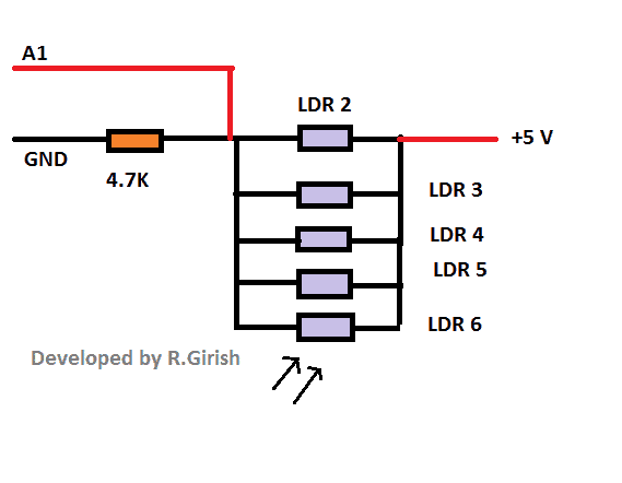
How to wire LDRs:
The LDR 2 is shown on the main circuit diagram; connect 4 more LDRs in parallel as shown in the above diagram.
Layout Diagram:
The above is the basic arrangement on how to place the laser. Please note that the distance between LDRs can be choice of the user depending on track length.
Program:
//------------Developed By R.Girish-------//

#include <LiquidCrystal.h>

LiquidCrystal lcd(12,11,5,4,3,2);

const int start = A2;

const int strt = A0;

const int END = A1;

boolean y = true;

boolean x = true;

unsigned int s1 = 0;

unsigned int s2 = 0;

unsigned int s3 = 0;

unsigned int s4 = 0;

unsigned int s5 = 0;

unsigned int m1 = 0;

unsigned int m2 = 0;

unsigned int m3 = 0;

unsigned int m4 = 0;

unsigned int m5 = 0;

unsigned int ms1 = 0;

unsigned int ms2 = 0;

unsigned int ms3 = 0;

unsigned int ms4 = 0;

unsigned int ms5 = 0;

unsigned int S = 0;

unsigned int M = 0;

unsigned int mS = 0;

unsigned int count = 0;

void setup()

{

lcd.begin(16,2);

pinMode(start, INPUT);

pinMode(strt, INPUT);

pinMode(END, INPUT);

if(digitalRead(strt) == LOW)

{

while(true)

{

lcd.clear();

lcd.setCursor(0,0);

lcd.print("Start Laser is");

lcd.setCursor(0,1);

lcd.print(" not working");

delay(2500);

lcd.clear();

lcd.setCursor(0,0);

lcd.print("Please align the");

lcd.setCursor(0,1);

lcd.print("lasers properly");

delay(2500);

lcd.clear();

lcd.setCursor(0,0);

lcd.print("and press reset.");

delay(2500);

}

}

if(digitalRead(END) == LOW)

{

while(true)

{

lcd.clear();

lcd.setCursor(0,0);

lcd.print("All 5 lasers");

lcd.setCursor(0,1);

lcd.print("are misaligned");

delay(2500);

lcd.clear();

lcd.setCursor(0,0);

lcd.print("Please align the");

lcd.setCursor(0,1);

lcd.print("lasers properly");

delay(2500);

lcd.clear();

lcd.setCursor(0,0);

lcd.print("and press reset.");

delay(2500);

}

}

lcd.clear();

lcd.setCursor(0,0);

lcd.print("-System Standby-");

lcd.setCursor(0,1);

lcd.print("Press Start btn");

if(digitalRead(start) == LOW)

{

while(x)

{

if(digitalRead(start) == HIGH)

{

x = false;

}

}

}

lcd.clear();

lcd.setCursor(0,0);

lcd.print("System is ready");

lcd.setCursor(0,1);

lcd.print("----------------");

while(y)

{

if(digitalRead(strt) == LOW)

{

y = false;

}

}

lcd.clear();

lcd.setCursor(0,0);

lcd.print("Time is being");

lcd.setCursor(0,1);

lcd.print("Calculated....");

mS = 12;

}

void loop()

{

delay(1);

mS = mS + 1;

if(mS==1000)

{

mS=0;

S = S+1;

}

if(S==60)

{

S=0;

M = M+1;

}

if(digitalRead(END) == LOW)

{

count = count + 1;

if(count == 1)

{

ms1 = mS;

s1 = S;

m1 = M;

delay(500);

}

if(count == 2)

{

ms2 = mS;

s2 = S;

m2 = M;

delay(500);

}

if(count == 3)

{

ms3 = mS;

s3 = S;

m3 = M;

delay(500);

}

if(count == 4)

{

ms4 = mS;

s4 = S;

m4 = M;

delay(500);

}

if(count == 5)

{

ms5 = mS;

s5 = S;

m5 = M;

Display();

}

}

}

void Display()

{

ms1 = ms1 + 500;

ms2 = ms2 + 500;

ms3 = ms3 + 500;

ms4 = ms4 + 500;

ms5 = ms5 + 500;

if(ms1 >= 1000)

{

ms1 = ms1 - 1000;

s1 = s1 + 1;

if(s1 >= 60)

{

m1 = m1 + 1;

}

}

if(ms2 >= 1000)

{

ms2 = ms2 - 1000;

s2 = s2 + 1;

if(s2 >= 60)

{

m2 = m2 + 1;

}

}

if(ms3 >= 1000)

{

ms3 = ms3 - 1000;

s3 = s3 + 1;

if(s3 >= 60)

{

m3 = m3 + 1;

}

}

if(ms4 >= 1000)

{

ms4 = ms4 - 1000;

s4 = s4 + 1;

if(s4 >= 60)

{

m4 = m4 + 1;

}

}

if(ms5 >= 1000)

{

ms5 = ms5 - 1000;

s5 = s5 + 1;

if(s5 >= 60)

{

m5 = m5 + 1;

}

}

while(true)

{

lcd.clear();

lcd.setCursor(0,0);

lcd.print("Spilt 1)");

lcd.print(m1);

lcd.print(":");

lcd.print(s1);

lcd.print(":");

lcd.print(ms1);

lcd.setCursor(0,1);

lcd.print("Split 2)");

lcd.print(m2);

lcd.print(":");

lcd.print(s2);

lcd.print(":");

lcd.print(ms2);

delay(2500);

lcd.clear();

lcd.setCursor(0,0);

lcd.print("Split 3)");

lcd.print(m3);

lcd.print(":");

lcd.print(s3);

lcd.print(":");

lcd.print(ms3);

lcd.setCursor(0,1);

lcd.print("Split 4)");

lcd.print(m4);

lcd.print(":");

lcd.print(s4);

lcd.print(":");

lcd.print(ms4);

delay(2500);

lcd.clear();

lcd.setCursor(0,0);

lcd.print("Split 5)");

lcd.print(m5);

lcd.print(":");

lcd.print(s5);

lcd.print(":");

lcd.print(ms5);

lcd.setCursor(0,1);

lcd.print("---Press Reset--");

delay(2500);

}

}

//------------Developed By R.Girish-------//
How to operate this Automatic Stopwatch:
• With completed setup, power the lasers on first and then turn on the Arduino circuit next.
• If all lasers are properly aligned with LDRs, the display will not prompt with error messages. If any, please align them properly.
• Now the circuit displays “System is standby”. Now press the “start” button and it will display “System is ready”.
• At this point the when the solo player interrupts the LDR 1 light beam, the timer starts and it displays “Time is being calculated….”
• As soon as the player reaches the end point i.e. LDR 6, the timer stops and it displays the 5 split time recorded by the circuit.
• The user has to press the reset button on the arduino to reset the timer.
Why this Automatic stopwatch can’t show live timing on the display as traditional stopwatch does (but rather it displays a static text “Time is being calculated….”)?
To display the timing in real time, Arduino has to execute additional instructions to LCD display. This will add few microseconds to few milliseconds delay to the main time tracking piece of code, which will leads to inaccurate results.
If you have any further queries, please express through the comment section.
Need Help? Please Leave a Comment! We value your input—Kindly keep it relevant to the above topic!