The discussed audio amplifier circuits are designed around the versatile L165V amplifier IC, which is quite adaptable in various scenarios.
Working Voltage Range
While the minimum recommended supply voltage is 12V, the L165 amplifier circuits show satisfactory operation even below 9V, albeit with somewhat reduced performance.
On the upper end, the absolute maximum supply voltage can go up to 36V, providing a considerable range of choices.
Opting for maximum power output implies selecting a supply voltage at the higher end of the spectrum. However, if accepting a diminished output is acceptable, the amplifier can function with almost any supply voltage.
Supply Connections
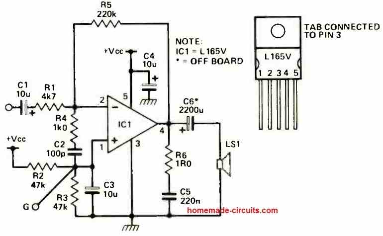
Moving on to the first L165 amplifier configuration depicted in Figure 1 below, if a single rail power supply is employed, a sizeable electrolytic capacitor (C6) becomes necessary between the output and the loudspeaker.


Alternatively, a split rail supply can be utilized by connecting 0V at point G on the board, attaching the positive rail to V+, and linking the negative rail to V-.
In this setup, components R2, R3, and C6 can be omitted, and the speaker may be connected between the output and 0V.
Nevertheless, it's crucial to note that the IC1 L165 tab internally connects to pin 3, adopting the negative rail voltage. Therefore, caution should be exercised while selecting a heat sink surface. Using insulating material is advisable if needed.
Using Bridge Configuration for the L165 ICs
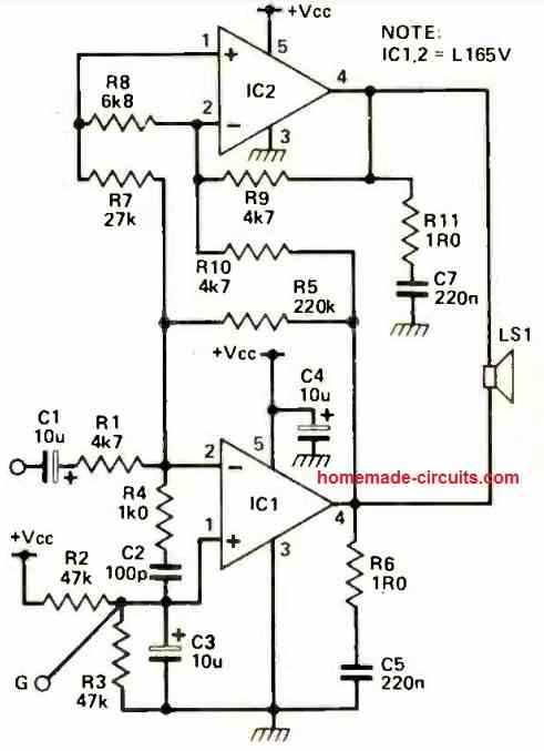
Moving to the second L165 amplifier arrangement illustrated in Figure 2 below, a bridge configuration is employed to achieve greater power output, especially at lower voltages where the maximum voltage swing limits the output.

This setup provides approximately four times the peak power of the single IC version as the speaker experiences a doubled voltage.
This characteristic renders it valuable as an enhancer for car stereo systems, provided the speakers can withstand the increased power.
For this circuit, a split rail supply is also an option, though it doesn't yield significant advantages. Once again, connecting 0V to point G, the positive rail to V+, and the negative rail to V- is the protocol.
The caution regarding the IC heat sink tabs still holds true.
With a split rail supply, these tabs will align with V-, hence they shouldn't be fastened to metalwork at 0V.
To ensure compatibility, verify with a voltmeter that both the tabs and the metalwork share the same voltage if there are any doubts.
Optimal Heat Dissipation Strategies
When it comes to managing heat dissipation, the prevailing principle is that bigger is indeed better.
Feel free to utilize finned extrusions if desired; however, if that's not the case, securely fastening the heat sinking tabs to the case's metalwork, a robust sheet of aluminum, or even the chassis of the loudspeaker are viable alternatives.
Applying a small amount of heatsink compound and ensuring a clean mounting surface are recommended practices to enhance heat transfer.
While observing that the ICs may appear to operate at elevated temperatures, there's no need for immediate concern.
These ICs can endure substantial heat; you could even potentially boil water on the heatsink before encountering significant issues.
Moreover, an integrated thermal shutdown feature is in place to safeguard against damage. Nevertheless, optimal efficiency is attained when maintaining a cooler operational temperature.
It's important not to operate the ICs without proper heatsinks, even when running at low power levels.
Power Supply Considerations
Regarding the power supply, a broad array of choices is available, catering to diverse preferences.
If aiming for outputs around 50W from the bridge circuit, a supply delivering approximately 30V at 3.5 amps will be essential. It's prudent to avoid employing supplies exceeding 32V.
While the ICs have demonstrated functionality at voltages up to 36V, exceeding this threshold could lead to their detriment.
To ensure safe operation, it's advisable to maintain a safety margin that accounts for potential ripple effects and various types of over-voltages that might occur within the supply system.
How the Circuit Works
The first amplifier configuration closely resembles the series feedback circuit commonly utilized with operational amplifiers (op-amps), where the gain is established through R5 and R1.
To supply a reference voltage of half Vcc to the non-inverting input of IC1, R2 and R3 are responsible. To enhance circuit damping and phase margin, R4 and C2 constitute a lag network.
These components prevent the amplifier from oscillating when the input is left floating and curtail overshooting during transients.
R6 and C5 collaborate as a Zobel network to minimize fluctuations in the load impedance seen by the amplifier's output.
With a split rail power supply, the speaker can be linked between the output and OV, rendering C6 unnecessary.
The cumulative offset voltage of the output, combining input offset and the bias current-induced voltage across R5, will peak at approximately 2mV at most. This value is trivial, obviating the need for offset adjustment.
The bridge circuit closely parallels the single IC circuit, but incorporates an additional amplifier with a gain of -1 to produce an inverted signal for the opposing end of the loudspeaker.
To achieve this, R9 and R10 create series feedback around IC2. By connecting the non-inverting input of the amplifier to the virtual ground point at IC1 pin 2, the necessity for adjusting the output offset is circumvented. R8's presence ensures stability.
Applications
The utility of amplifier modules hardly requires emphasis, given their broad applicability.
However, the compact dimensions, robust power output, and remarkable resilience to supply fluctuations collectively contribute to the exceptional versatility of these diminutive units.
Enhancing Car Stereo Systems and Beyond
The L165 bridge amplifier configuration notably offers a valuable enhancement for car stereo systems.
Beyond that, its suitability extends to other scenarios demanding reasonable output with limited supply voltage.
Both modules excel as sound output solutions, making them ideal for a range of projects.
Their compatibility with a wide range of supply voltages is noteworthy, while their compact form ensures minimal spatial requirements.
A Remarkable Fit for Hi-Fi Systems
Furthermore, these L165 amplifier modules seamlessly integrate into high-fidelity setups.
Their frequency response remains impressive, showcasing minimal output drop even at higher power levels up to several hundred kilohertz (a measurement achieved through scope analysis, as audible limitations of both ears and speakers manifest long before that point).
Impressively, the circuit's noise and distortion levels are remarkably low, a testament to its simplicity. For enthusiasts of rock music, these modules deliver a substantial sonic impact.
Underrated Potential
Underestimating these modules would be a mistake. Their capabilities extend beyond initial expectations, proving themselves as robust and versatile components across diverse audio applications.
Parts List
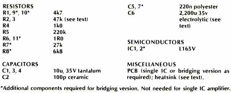
The following data provides the complete parts list for the above L165 amplifier project:

Need Help? Please Leave a Comment! We value your input—Kindly keep it relevant to the above topic!