

In this article I have explained using circuit diagrams how a clipper and a compressor circuits work to processes an input audio signal as per the required output signal.
What is an Audio Clipper
An audio clipper circuit is basically used to alter or restrict the amplitude (volume) of an audio signal. There are mostly two kinds of clippers:
Hard Clipper Circuit: A hard clipper circuit suddenly restricts the audio signal's loudness at a specific audio signal threshold level, . When the signal rises over this limit, it is "clipped" or flattened, producing distortion and an output that resembles a square wave.
Soft Clipper Circuit: Contrary to a hard clipper, a soft clipper progressively softens down the audio signal's peaks as it gets close to the threshold level. As a result, when the signal crosses the threshold, the distortion is smoother and more realistic.
In conclusion, audio signals with hard clippers have a harsh, abrupt distortion, whereas those with soft clippers have a smoother, more subtle distortion.
Hard Soft Clipper Circuit
To compress the dynamic range of an audio signal, a gain-controlled or gain-limited stage is typically utilized, which is particularly effective in applications such as speech compression on PA systems and transmitters.
A gain-controlled stage is inherently more intricate compared to a gain-limited stage, often referred to as a clipper.

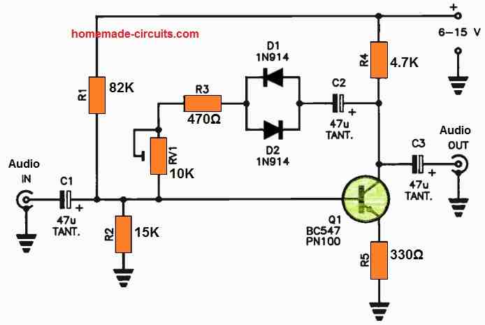
The simplest audio clipper circuit configuration as shown above involves the use of a pair of diodes arranged back-to-back, limiting the signal's voltage swing to approximately 0.6 V, resulting in a form of hard clipping where the input signal waveform is essentially truncated or clipped sharply at the peak.
This particular circuit employs a pair of back-to-back diodes within the feedback path of a single-stage transistor amplifier.
It incorporates a potentiometer control that may be used to vary the clipping characteristics, ranging from soft to hard.
When RV1 is set to its minimum value, it produces hard clipping, whereas at its maximum, it generates soft clipping.
It's worth noting that the stage's gain can be adjusted by altering the ratio of R4 to R5, with resistor R5 introducing a degree of degenerative feedback.
Following the stage, it is advisable to implement a low-pass filter to attenuate any harmonics produced during the clipping process.
Although tantalum capacitors are specified for use in this circuit, low-leakage alternatives can be substituted if needed. Any commonly available small-signal transistor can be employed for Q1.
This circuit should be integrated immediately after the microphone input stage.
Audio Clipper with Minimum Distortion
The issue commonly encountered with most audio signal clippers lies in their tendency to produce harsh harmonics due to the inherent asymmetry in many circuits.

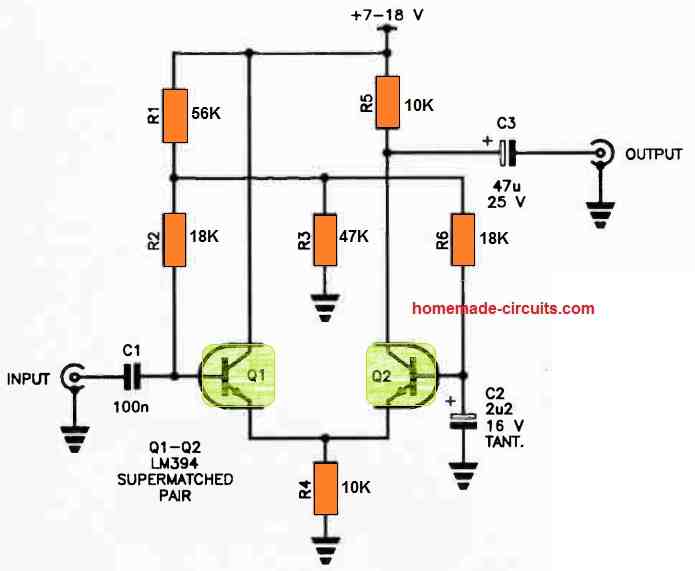
This particular circuit addresses this problem by employing a pair of super-matched transistors, namely the LM394.
The LM394 features a unique construction where two transistors are intricately etched onto a single piece of silicon, ensuring an extremely close match in their characteristics.
Within this circuit, Q1 functions as the input stage and operates in a common-collector configuration, while Q2 serves as the output stage, operating in a common-base configuration.
This setup proves effective in achieving symmetrical clipping of the signal when overdriven at the input.
To establish proper biasing, R1 and R3 work together as a bias divider network, and R2 and R6 function as base isolation resistors. The circuit boasts a unity gain, and its input impedance is notably high.
What is an Audio Compressor
An audio compressor circuit is basically designed to minimize the dynamic range of an audio signal.
This is achieved by attenuating the amplitude of high audio peaks and boosting the quieter signal ranges.
This audio processing produces a more consistent and controlled output.
This helps to balance the audio output levels, causing the softer audio signals to become louder, and preventing distortions from extremely high audio peaks.
Compressor Circuit (Log)
Unlike clippers that compress the dynamic range of an audio signal once it surpasses a specific threshold, a compressor circuit with an input:output behavior closely resembling a logarithmic V [log.] curve delivers gradual signal limiting across an extensive range.
This results in a smoother compression effect.

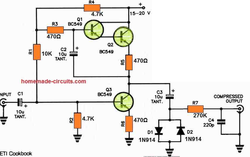
This particular compressor circuit shown above exhibits a highly effective logarithmic input:output characteristic across a dynamic range spanning approximately 60 dB.
It achieves this through a pair of back-to-back diodes driven by a current generator, producing an almost ideal logarithmic transfer characteristic.
It's crucial to select diodes with closely matched forward resistance properties for optimal performance.
When it comes to polarized capacitors, you have the option of using either tantalum capacitors or low-leakage electrolytics.
Additionally, R7-C4 combination serves as a low-pass filter in this configuration. For optimal results, this stage should be inserted directly after the microphone amplifier.
An Alternative Logarithmic Compressor Design
This circuit shown below illustrates a method for achieving a logarithmic input:output characteristic in an amplifier stage, potentially serving as a compressor.

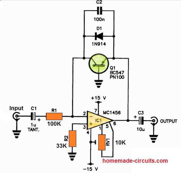
The circuit capitalizes on the logarithmic characteristic inherent in the base-emitter junction of a transistor.
In this setup, the transistor is integrated into the feedback loop of an operational amplifier (op-amp).
Virtually any small-signal transistor can be utilized for this purpose.
Diode D1 is employed to restrict the output voltage swing, while RV1 is finely adjusted to nullify the op-amp's output offset voltage, setting it to zero.