
We are happy to share an automatic curtain control circuit kindly provided by Mr. August Peterson. This design helps to open and close curtains by sensing light from the surroundings. It uses an LM393 comparator, a solar panel as a light sensor and a 24V motor. The circuit makes the curtain open in the morning and close in the evening without needing anyone to operate it.
Mr. Peterson's design is very useful because it uses recycled parts. Some parts are taken from an old UPS, a check scanner motor, and microwave limit switches. This helps to save money and protect the environment.
We sincerely thank Mr. August Peterson for sharing this circuit with us. His work will help many electronics learners and hobbyists.
In this article we will explain the circuit diagram, how it works, and the parts needed so you can make your own automatic curtain system.
Here's the email sent to me by Mr. August, which provides the basic working details of the design:
Overview
Hi Swagatam,
I was not able to find a simple circuit to open and close a set of curtains automatically. I set out once again developing one using as many recycled parts as possible and would have preferred to use an H-bridge for motor control but it resulted in a higher component count and trickier circuitry, so I used 2 relays.
It is a fit and forget project unless you wish to operate the curtains manually for some reason, then there is a manual / automatic switch and an open & close button.
I actually mounted the LED, the auto/manual switch and the open & close button in a small box on an extended cable for convenience because the mechanism is installed too high to reach without a step ladder.
I used substantial micro switches as the limit switches because you cannot have a limit switch failure - the consequences would be mechanical damage at least.
If you are interested you can access the circuit using your Mega link and look in the Auto Curtain Controller Folder.
If you encounter any difficulties, please let me know and I will send you a new link.
Keep up your good work and best regards from August.
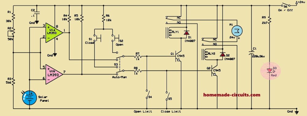
Circuit Diagram
Components and How They Work
Ok, so this circuit is basically an automatic curtain controller. It works using an LM393 comparator and a motor system that is controlled by relays. Now let us see how everything works step by step.
LM393 Comparator
We are using an LM393 IC which is a dual comparator. This means it has two separate comparators inside it, called U1a and U1b.
The first comparator U1a is used to detect when it is dark.
The second comparator U1b is used to detect when it is bright.
There are some resistors (R1, R2, R3) that help to set a reference voltage. This reference voltage is used for comparison.
Light Detection
Now, to detect light we are using a solar panel. This solar panel works as a sensor. It generates a voltage based on the amount of light falling on it.
Then, when it becomes dark, the voltage at the non-inverting input of comparator U1a becomes higher than the voltage at its inverting input. Because of this, the output of U1a becomes high.
Then, when it is bright on daytime, the voltage at the non-inverting input of comparator U1b becomes higher than the voltage at its inverting input. So the output of U1b becomes high.
Transistor and Relay Control
The output from each comparator is connected to an NPN transistor (Q1 and Q2 - C945). These transistors help in controlling relays.
Then, if the output of U1a goes high, transistor Q1 turns ON. This activates Relay RLY1.
Next, if the output of U1b goes high, then the transistor Q2 turns ON. This activates Relay RLY2.
The relays are used to control the direction in which the motor will rotate.
Curtain Movement
After this when it is dark, the Relay RLY1 gets activated. This makes the motor rotate in one direction, and the curtain starts closing.
Then, when it is day bright, the Relay RLY2 gets activated. This makes the motor rotate in the opposite direction and the curtain starts opening.
Limit Switches (S4, S5)
To make sure the curtain stops at the correct position, we are using two limit switches.
Further on, when the curtain is fully closed then the limit switch S4 stops the motor.
Then, when the curtain is fully open, the limit switch S5 stops the motor.
Manual Override (S1, S2, S3)
Now, sometimes we might want to control the curtain manually. For that we have three switches.
Then, if we press S1, it will move the curtain in one direction manually.
Next, if we press S2, it will move the curtain in the other direction manually.
Again, if we press S3, it will now switch between automatic mode and manual mode.
Power and Protection
The whole system runs on 24V DC power.
Now if the relays turn OFF, then there can be voltage spikes. To protect the transistors from these spikes, we are using flyback diodes (D1 and D2 - 1N4007).
There is also a capacitor C1 (220uF/36V), which helps to stabilize the power supply and reduce noise.
We have an LED (D3 - Red), which works as an indicator light.
Wrapping up
The LM393 IC works like a bistable switch, meaning it changes state based on light levels.
When it becomes dark, then the motor starts closing the curtain. It keeps closing until limit switch S4 stops it.
Once daylight comes, the motor then starts opening the curtain. It keeps opening until limit switch S5 stops it.
The relays decide in which direction the motor will move.
If you do not want this automatic control, then you can just use the given switches to move the curtain manually.
But basically, this circuit makes sure that the curtain opens and closes by itself based on the surrounding light.
Main Components:
| Component | Specification/Description | Quantity |
|---|---|---|
| ICs | LM393 (Dual Comparator) | 1 |
| Transistors | C945 (NPN Transistor) | 2 |
| Relays | 24V, 880-ohm (from redundant UPS) | 2 |
| Diodes | 1N4007 (Flyback protection for relays) | 2 |
| Resistors | R1 - 38kΩ | 1 |
| R2 - 50kΩ (Variable Potentiometer) | 1 | |
| R3 - 5.6kΩ | 1 | |
| R4 - 10kΩ | 1 | |
| R5 - 10kΩ | 1 | |
| R6 - 10kΩ | 1 | |
| R7 - 1kΩ | 1 | |
| R8 - 1kΩ | 1 | |
| R9 - 2.7kΩ | 1 | |
| Capacitors | C1 - 220µF / 36V (Power stabilization) | 1 |
| C2 - 0.1µF (Noise filtering) | 1 | |
| Switches | S1 - Manual Close Button | 1 |
| S2 - Manual Open Button | 1 | |
| S3 - Auto/Manual Switch | 1 | |
| S4 - Open Limit Switch (from scrap microwave) | 1 | |
| S5 - Close Limit Switch (from scrap microwave) | 1 | |
| S6 - Power On/Off Switch | 1 | |
| Motor | Part #146130 (from redundant check scanner) | 1 |
| DC 24V, 90mA, 147 min⁻¹, 4.5 Ncm | ||
| Sensor | Solar Panel (from Garden LED lamp) | 1 |
| Indicator | D3 - Red LED (Status Indicator) | 1 |
| Power Supply | 24V DC (for motor and relays) | - |