In this post I have explained a 3 beautiful fish aquarium light optimizer circuits your fishes will love. These are designed to automatically control the illumination of a group of appropriately selected LEDs with respect to the varying daylight and after darkness sets in. The first idea was requested by Mr. Amit
1) Sun light Dependent Aquarium Light
I liked your Automatic 40 Watt LED Solar Street Light Circuit Project, but I am looking is a bit other way round.
1) LDR is in open, broad day light outside the House.
2) Series of LED (White RED BLUE GREEN ratio (3:1:1:1) is inside the house on the Fish Tank.
3) As the Day light gets Brighter, the LED glows brighter.
4) gets Dimmer in evening and Off when Sun Sets.
5) A low Watt Blue LED Strip depicting calm moon light keeps going when Bright LED are off.
6) Powered by Solar energy
7) Can a generic circuit be made with more Solar panels to generate more power and Cater 3 tanks ?
simulating day light is very important for a marine tank. do you like the concept?

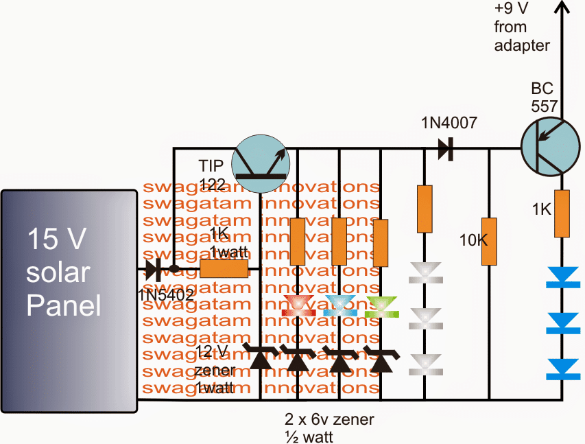
The Design
As shown in the diagram the proposed automatic fish aquarium light optimizer circuit consists of just a couple of transistors as the active components, wherein the NPN device is configured as a common collector while the other PNP as an inverter.
During day time the solar panel produces the specified amount of light conversion supplying the common collector stage with the required amount of voltage.
The NPN transistor base is restricted with a maximum of 12 V with the aid of the connected zener which in turn ensures that the potential across the connected red, blue, green, white LEDs never exceeds this value regardless of the solar panel peak voltage levels.
During dusk when the solar panel light begins deteriorating, the LEDs also experience a proportionately diminishing voltage conditions simulating a proportionately dimming effect in their illumination levels, corresponding to the sunlight....until it's almost dark when these LEDs completely shut off.
In the meantime, as long as the solar panel voltage maintains an optimal voltage the PNP is forced to stay shut off, however as the sun begins to set, the potential at the base of the PNP device begins falling and when it falls below the 9 V mark, prompts the connected blue LEDs to brighten up slowly until these become fully lit after dusk.
The process gets reversed at daybreak, and the cycle keeps repeating simulating a day/night cycle light effect inside the fish aquarium
The 9 V at the emitter of the PNP may be derived from any standard 9 V AC/DC adapter or simply from a cell phone charger unit.
2) LED Illumination for Fish Aquariums using IC 4060
The next discussed LED light circuit with timer was requested by Mr.Nikhil for illuminating his 4 x 2 feet fish aquarium. I have explained more about the proposed circuit idea.
Technical Specifications:
Hi, I wanted to make a led lighting for my 4x2ft aquarium. I need at least 400 straw-hat led circuit each of 5mm. can you please design the circuit!
The Design:
The fish aquarium LED light with timer circuit presented here utilizes a standard fish aquarium LED light set-up design for the required illuminations.
Two sets of LED colors are used, blue and white, which illuminate in tandem at an interval of 12 hours each. The switching is controlled through a simple IC 4060 timer circuit.
The white LEDs light up at 9 am and switch OFF at 9 pm, switching ON the blue LEDs. The blue LEDs remain illuminated from 9pm until 9am, when it's again replaced by the white LEDs....the cycle goes on as long as power remains available to the circuit. A standard ratio of 1:6 is used for the LEDs, i.e. around 348 white LEDs and about 51 blue LEDs.
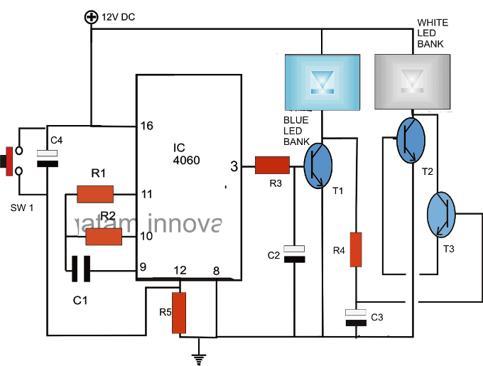
Circuit Operation:
The diagram shows a simple circuit based upon the universal timer IC 4060 for implementing the sequencing operations of the involved LEDs.
The product of R2 and C1 determines the timing frequency, which must be set roughly for generating 12 hour intervals.
C1 may be taken as 0.68uF, while R2 may be appropriately selected for generating the above time frequency through some trial and error.
A small value resistor say a 1K may be selected for R2 to check what time interval it generates, once we get this, the value for 12 hour may be easily calculated through cross multiplication..
If after a few days the time intervals seem to be drifting away from the set start/finish hours, the switch SW1 may be pressed for resetting the sequence.
If required this can be done every morning at 9am for implementing accurate switching of the LEDs, and for maintaining a natural feel inside the aquarium habitat.
Let's assume the circuit is switched ON at 9 in the morning. The output pin#3 of the IC initiates with a logic low and the timer starts counting.
The low at pin#3 keeps T1 switched OFF, this creates a high potential at the collector of T1 which instantly triggers T3/T2 illuminating the white LEDs.
The white LEDs remains illuminated for so long the timer counts, and the moment the set time lapses, the output of the IC goes high (after 12 hours), this instantly switches ON T1 and the associated blue LEDs and switches OFF T2/T3 and the white LEDs.The cycle repeats as long as the circuit remains powered.
C2 and C3 helps to illuminate the respective LED banks gently, in a cool fading manner.
Parts List
- R1 = 2M2
- R2/C1 = see text
- R3 = 470 Ohms
- R4 = 10K
- R5 = 100K
- T1,T3 = 8050
- T2 = TIP122
- C2/C3 = 470uF/25V
- C4 = 1uF/25V
- IC = 4060
- SW1 = push to ON switch (push-button)
- LEDs = Blue 51 nos, white 348 nos. (super bright, roughened at the surface through a grinder wheel)
LED Bank Connections
The white LED bank is made by connecting 116 nos. strings connected in parallel. Each string consists of 3 white LEds with a 150 Ohms resistor.
The blue LED bank is also made in the above fashion using 51 nos. blue LED strings in parallel.
Using High Watt LEDs and Drivers
The above design could be used for operating high watt LEDs with special 220V drivers, as shown below:
Note: Please add 2200uF/25V capacitor across the LED modules pins so that the switching transitions are seamless and not abrupt.
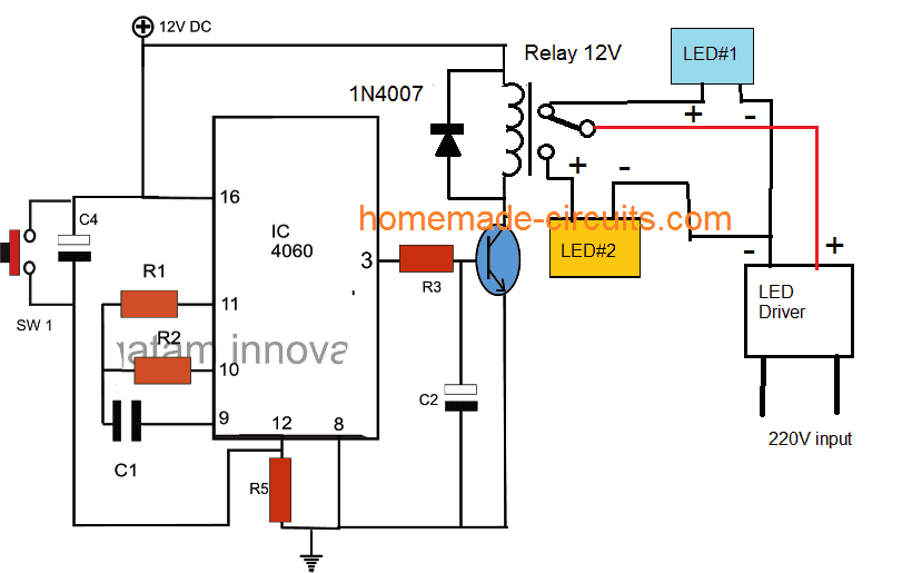
3) Fading LED Light Timer Circuit for Fish Aquariums
The third circuit is designed for creating a fading LED light effect which can be set for operating in fish aquariums in the prescribed manner for a predetermined length of time. The idea was requested by Mr. Jaco.
Technical Specifications
My name is Jaco and I am from sunny South Africa. I have an aquarium that I want to "modify" the lights on. I would like a circuit based on a cd4060 chip that can bring multiple strings of LED's from power off to max brightness and the reverse over a period of 8 - 12 hours.
I'm going to use set times to explain what I would want to happen. The actual timing will obviously not be that perfect. But here goes.
My basic idea - at 6am the circuit should start lighting up slowly to max brightness until 11am.
It should then stay on max brightness until 1pm.
Then slowly dim from max brightness to off at 5pm.
It should stay off until 7am the next morning when the cycle restarts. An arduino circuit will unfortunately not work for me, as I cannot get my hands on one.
Thank you in advance.
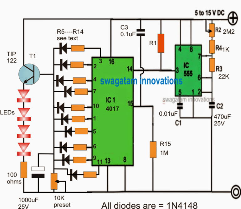
The Design
The requested fading LED light circuit for illuminating fish aquariums can be visualized in the above diagram.
I have used a 555 IC by mistake for generating the delay time interval, however a 4060 IC based circuit may be also effectively used in place of the IC 555 stage, in fact a 4060 circuit would be able to produce a 10 times bigger delay effect reliably, than the IC 555 counterpart.
The time interval oscillator section which is formed by the IC 555 produces the required sequence pulses for the attached 4017 IC which is a Johnson decade counter and divide by 10 IC. It becomes responsible for creating a shifting high logic across the shown 10 output starting from pin#3 to pin#11.
Meaning with every pulse generated from the IC 555 pin#3 at pin#14 of 4017 will cause the supply voltage to shift from its pin#3 (start pin) to the subsequent pinouts (2, 4, 7...etc), this implies that if the delay time between each pulse from the IC 555 is say 1/2 an hour, this would cause the high logic from pin#3 to pin#11 of the IC 4017 to consume around 1/2 x 10 = 5 hours.
The outputs of the IC 4017 can eb seen configured with a emitter follower transistor circuit formed around TIP122 which is a Darlington transistor and thus features a high current response across its base and emitter pinouts.
Since it's configured as an emitter follower ( or as a common collector), it ensures the generation of a precisely identical (almost) voltage across the load, connected at its emitter/ground, equivalent to the voltage applied at its base.
It Implies that if the voltage at its base is 3V, then the voltage at its emitter would be around 2.4V (the 0.6V drop is inherent and cannot be avoided).
Similarly if the voltage at the base of the TIP122 is 6V, this will be interpreted as a 5.4V across its emitter...and so on.
This is the reason why the configuration is named "emitter follower", meaning an "emitter" lead which follows the base lead voltage of the transistor.
We can see an array of resistors connected across the pinouts of the 4017 IC which in turn is attached with the base of the TIP122 transistor, in conjunction with a 10k preset across the base and ground of the transistor.
These resistors across the 4017 outputs are arranged in an incremental value, such that it corresponds with the set 10k preset value and forms a potential divider network.
The voltage developed at the junction (base of the transistor) of this potential divider in response to the sequencing high across the relevant pinouts of the IC can be expected to be in an increasing order.
This incrementing potential difference order can be assigned across a few outputs of the IC 4017, say up to pin#4.
So the TIP122 can be assumed to respond to these incrementing potentials and produce an equivalently incrementing voltage at its emitter pin, which in turn makes sure that the connected LEDs go through a gentle reverse fading effect and become brighter slowly.
The 1000uF capacitor connected in parallel to the preset further aids to the effect and causes the above reverse fading to happen at a slow and a gradual manner.
Once the sequence reaches pin#7 and subsequently to pin#10, 1 and 5, these pinouts resistors can be selected such that a maximum voltage is generated at the base of the transistor with reference to the preset value.
This in turn enables the LEDs to stay illuminated at the maximum brightness, until the sequence has crossed these pinouts and reached pin#6, and subsequently to pin#9, 10 and pin#11.
The resistors in these pinouts may be fixed in a demoting fashion such that the potential difference generated at the base of the transistor goes through a falling potential level, which in turn is induced over the LEDs for generating a nice and slow fading effect.
The 1000uF capacitor at this point now acts in a reverse manner, and allows the fading to take place rather slowly, until the LEds are finally shut off as the sequence reaches the pin#11 of the IC4017.
After this the operation reverts to pin#3 and the cycle repeats as explained in the above discussion.
UPDATE:
In the above design I seemed to have missed the 24 hour resetting stage in the circuit, the following new improved version of the fading LED light timer circuit takes care of this feature and operates the LEDs exactly as per the mentioned request.
Adding 24 Hour Resetting Feature
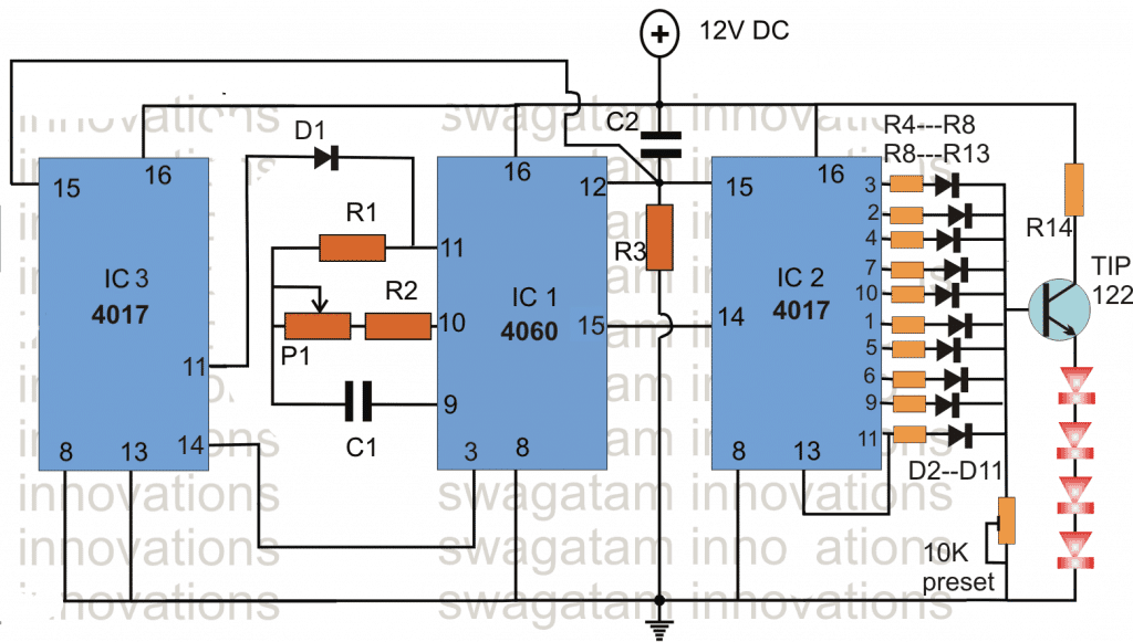
Here the IC 4060 is used as a timer oscillator whose pin#15 is used for generating a relatively faster frequency for the IC2, such that the outputs of IC2 are able to generate the required slow glow and slow fade sequencing effect on the LED driver transistor within 12 hour period.
On the other hand pin#3 of the IC 4060 which generates around 7 to 8 times slower frequency than pin #15 clocks IC3 appropriately, and this inclusion becomes responsible for the 24 hour resetting feature in this new circuit.
Pin#15 and pin#3 are arbritarily chosen here with an assumption that pin#15 would enable the LEDs to operate for 12 hours, while pin#3 pulse rate will reset the IC1 after every 24 hours via IC3.
This timing will need to be tested with some trial and error using the available extensive range option that IC1 and IC3 are able to provide through their 10nos of output pins, and these may be experimented for getting the most favarable timing range across both the features, that is for 12 hour LED effect and for the 24 hour reset.
Also do not forget the P1 adjustment which further adds to the adjustment range of the design.
Parts List
R1 = 2M2,
R2, R3 = 100K,
P1 = 1M pot
C1 = 1uF
C2 = 0.22uF
R4--R8 = value in decreasing sequence (needs to be calculated with respect to the 10k preset setting)
R8--R13= value in increasing sequence (needs to be calculated with respect to the 10k preset setting)
all diodes = 1N4148
Hi Swagatam
I’ve recently combined three circuits from the internet into one. Circuit 1 is a fixed frequency triangle wave circuit using a LM358 dual OPAMP chip. Circuit two is a photodiode amplifier circuit also using a LM358 dual OPAMP chip Circuit 3 is just a LED driver using the PWM signal from the previous two circuits. This circuit works quite well, however, I would like to make a few changes that I just can’t seem to wrap my head around:
1. The duty cycle seems to be from 0% to 100%. I would like to change this to 5% to 95%
2. There is a DC offset in the first circuit that I just can’t vary. Any way to make it variable?
If the links are not showing, please e-mail me so that I can send you the pictures.
Thanks in advance
Hi Jaco,
I’ll have to check the entire schematic which you have designed to actually understand how the circuit is designed to work, and regarding the possible modifications, my email is
homemadecircuits
@ gmail.com
Plz give me a circuit wich can change polarity after 1 minute