In this post I have explained a simple method of automatically switching ON an inverter fan whenever the unit is operating in the charging mode or inverter mode, in order to ensure optimum cooling of the internal power devices. The idea was requested by Mr. Sudip Bepary.
Circuit Objectives and Requirements
- I have just bought a new sine wave ups card (850va) (pic16f72)... It's working good.But, this board does not have cooling fan terminal.
- My transformer and Mosfet is getting hot at the condition of inverting and charging.
- So, please respond me with proper guide to connect DC cooling in this board to which the fan can on at time of charging and inverting.
- Please, please, please help me from this problem.
The Design
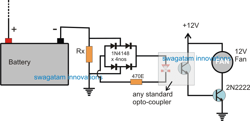
The requested idea for an automatic inverter fan switch ON circuit while the inverter is in the inverting mode or charging mode can be implemented using the following explained concept:

As can be seen in the figure, the negative of the battery is connected with a series Rx resistor such that any current whether from the charger or from the inverter passes through this resistor during the irrespective operations.
This implies that during any of the operations the resistor Rx is able to generate a proportionate amount of potential drop across itself enabling the connected sensing circuit to respond to this developed voltage.
A bridge rectifier can also be seen connected across Rx to ensure that it always produces a single polarity voltage regardless of the polarity of the current that may be passing through Rx.
For example while charging the battery the current polarity could be the opposite compared to the inverting mode polarity, however the bridge rectifier corrects both the possibilities and offers a single polarity output for the next stage which is an opto coupler stage.
The optocoupler LED lights up whenever the battery is operated by some method and this is instantly converted into a triggering voltage for the BJT 2N2222 associated with the optocoupler transistor.
The 2N2222 along with the opto transistor is configured in a Darlington mode to ensure a high gain for the BJT pairs which in turn makes sure that the Rx value can be selected to be as small as possible, thereby allowing minimum resistance for the inverter operations.
As soon as the 2N2222 conducts it turn ON the connected fan which begins cooling the vital devices of the inverter and makes sure that they are never hot and vulnerable during the charging process or while the inverter is in the inverting mode.
Calculating the Current Limiter Resistor
The Rx value may be selected with some trial and error. The LED could be expected to illuminate just slightly at around 0.7V, therefore the formula for calculating Rx can be expressed as
R = V/I = 0.7/I
I (current0) could be selected to be 50% of the calculated charging current, since at this current the power devices could be expected to be just getting warm.
Let's assume if the charging current is 10 amps, then the formula could be handled in the following manner
R = 0.7/5 = 0.14 ohms
Similarly other proportionate values of Rx could be calculated for successfully initiating the proposed automatic inverter fan switch ON during charging and inverting mode of the unit.
