In this post we investigate a circuit, designed for implementing an automatic sliding gate or door action, and includes a set of features as specified in the request. The idea was suggested by Mr. Andreas.
Technical Specifications
Can you help me to design a simple sliding gate controller. How can work its like this...Press a switch and open the gate, after a minute the gate close again.
If during the closing someone passing in front of the gate then the gate opens again(with the help of infrared cell??).
Reaching at the end(Stopping) during opening and closing its made by magnetic or limit switch.. Note this system must work on 24V.
Many thanks,
Andreas Christodolou
The Design
The proposed automatic sliding gate controller circuit may be understood as explained in the following points:
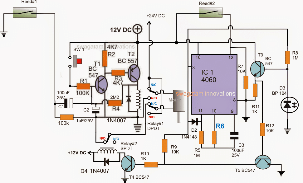
Referring to the circuit below, it can be divided into three stages: the set-reset latch using T1/T2, the monostable timer using IC 4060 and the IR interceptor using T3/T5.

Note:
- Please disconnect the 100k below C1 from the ground, and connect it on C1 positive terminal, meaning the 100k should be connected right across C1 terminals and nowhere else.
- R6 needs to be calculated for getting a 1 minute delay before the gate initiates a reverse closing motion
Let's assume the gate to be in the "closed" position with Reed#2 actuated by the relevant gate magnet.
This ensures pin#12 of the IC 4060 to be rendered high and the IC stays inactive (pin#3 switched OFF).
In the above scenario, the relay#1 is already OFF, with its N/C position closed (because T1/T2 are OFF), and T4 is also OFF due to the absence of a base drive, which implies relay#2 is OFF and in the N/C position.
With relay#2 in N/C, the motor is switched off due to the absence of a positive link via the relay#2 N/O contact.
The entire circuit is thus in a switched OFF condition.
Now, as requested, the opening of the gate is initiated by pressing SW1 momentarily.
Pressing SW1 instantly latches T1/T2 via R4, toggling relay#1 such that its N/O contacts close, which in turn forces the motor to slide the gate towards the "open" direction.
As soon the gate slides away from its "close" position, reed#2 is released, which instantly enables the IC 4060 and it starts counting, with its pin#3 now with a logic zero.
The gate rolls on until it reaches the extreme end when the other relevant magnet fixed on the gate activates reed#1.
On activation, reed#1 pulls the base of T1 to ground via C1, breaking the latch, which in turn deactivates relay#1 and its contacts return to their N/C points.
However relay#2 still being in a switched OFF condition causes the motor to halt due to the absence of power through relay#2 (N/O) points.
In the meantime, IC 4060 completes its counting allowing a high to appear at its pin#3. (the IC now latches in this position via D2)
This immediately activates relay#2, enabling a reverse activation of the motor.
The motor starts sliding the gate towards the "close "position, and the moment it reaches the "close" end, reed#2 is activated yet again. At this position, the IC is again reset causing a no signal at its pin#3, deactivating relay#2 and....shutting off the motor. The circuit reverts to its original standby state.
Calculating the Time Delay
The universal equation for finding the timing component Rt and Ct values is:
f(osc) = 1 / 2.3 x Rt x Ct
2.3 is just a constant with regards to the ICs internal configuration.
Preventing Accidental Entry
As per the request, the circuit needs to respond to an accidental entry of an individual through the gate in the course of its closing process, in order to safeguard the individual and also the gate mechanism.
This is implemented using an infrared transmitter receiver assembly, as shown in the diagram.
D3 is a receiver IR photodiode which is kept switched ON through a perpendicular IR activated transmitter beam, focused on D3, the beam position is supposed to be in a straight line along the gate's sliding action.
As long as D3 stays actuated, T3/T5 are unable to conduct, however in the presence of an individual who may be trying to make a quick entry across the gate while its closing, would in the course obstruct the IR beam, triggering T3/T5 which in turn would conduct and disable T4, and relay#2.
With relay#2 disabled, the door would instantly stop its closing motion and halt on the spot until the individual has completely crossed the restricted line of action.
For the sake of simplicity, a momentary halting of the gate looks more appropriate, instead of enforcing a reverse opening action which might unnecessarily delay the process.
Using a Transistorized Timer Stage
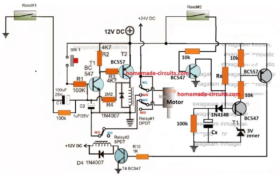
The above could be much simplified by replacing the IC 4060 timer stage with transistorized delay ON timer, and by removing the IR detector stage. The complete circuit diagram could be witnessed below:

The IR Transmitter Stage
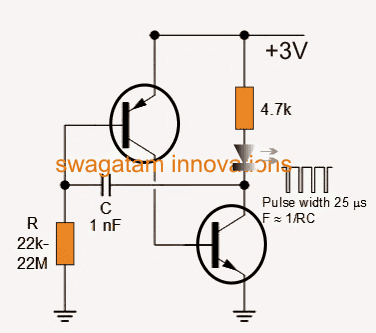
The IR transmitter which is supposed to focus a beam on D3 may be built using the following circuit:
