An automatic voltage regulator circuit is quite well used where Voltage supply is only 120VAC. Many gadgets can operate good at 220V Ac that is why Voltage regulation is needed.

By: Mehran Manzoor
For this matter an appropriate voltage Regulator circuit is designed which can operate up to capacity of 1KW and gives Variable voltage at different steps (ranges).

Circuit Operation:
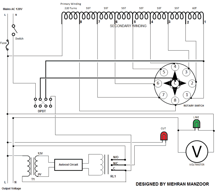
The Mains 120V AC Line and Neutral contains a switch and a fuse up to 10A. The DPDT Switch is used for Voltage up and Down. DPDT Switch has a four ends.
The Neutral from mains enters directly in first end of DPDT and the Line/Phase enters the transformer primary winding which is of 220 Turns of 6 layers.
It has seven Secondary Winding of 55 turns and one winding of 60 turns. These windings are connected to Rotary switch 1 to 8 respectively. The rotary switch has eight steps which can selected on by one.
The common of rotary switch are connected to second end of DPDT switch. The third end of DPDT are connected to first secondary winding of transformer.
The last end of DPDT are connected to Common of relay. The relay in a circuit is used for Auto cut off.
The N/O of Relay becomes the first output Mains AC Supply.
The N/C of relay is connected to first terminal of Red Neon lamp as an indicator to detect the auto cut off. the other terminal of Red Neon lamp is connected to other terminal of output Supply which is common to circuit. It directly comes from Line/Phase wire of Input mains 120V AC.
The common of relay is connected to fourth end of DPDT switch and second terminal of 500mA transformer for sensing the voltage. the relay can operate from Auto cut Circuit as shown in Diagram.
The Voltmeter is connected parallel with Green Neon Lamp to output Supply which indicates the presence of power and voltage across the output terminals

Auto cut Circuit:
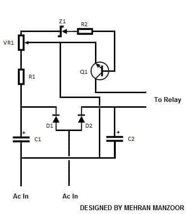
The above automatic voltage regulator circuit clearly shows that AC 12V enters through 500mA Transformer to auto cut circuit.
The two Capacitors C1 and C2 adjoining with D1 and D2 produces first terminal to relay and other terminal can be adjusted by preset which are joined to emitter of Transistor Q1.
The output produced by collector becomes another terminal to relay. the value of the preset can be adjusted as per required. When the voltage is reached above the adjusted value the circuit automatically cuts off.
Parts Required for Auto cut circuit:
C1-C2: 100μ 25V
D1-D2: 1N4007
R1:1.5KΩ
R2:220Ω
VR1: 5K preset
Z1: 8.2V
Q1: BC547

Have Questions? Please Comment below to Solve your Queries! Comments must be Related to the above Topic!!