The post below discusses an automatic voltage analyzer circuit which can be used for understanding and verifying the output conditions of an AVR. The idea was requested by Mr. Abu-Hafss.
Technical Specifications
I want to make an analyzer for Automotive Voltage Regulator (AVR).
1. The three wires of the AVR are connected to the corresponding clips of the analyzer.
2. As soon as the analyzer is switched ON, it will apply 5 volts at INPUT and read the polarity at the output, C.
3. If the output is positive the analyzer should light up a green LED. And the voltage to be monitored across the C and B.
Alternatively:
If the output is negative the analyzer should light up a blue LED. And the voltage to be monitored across the A and C.
4. Then the analyzer should increase the voltage further at the input until the voltage at output drops to zero. As soon as the voltage drops to zero, the input voltage should be hold and the analyzer should display that voltage on a DVM.
6. That’s all.
Circuit Analysis In Details
The difference between an IC voltage regulator and an automotive voltage regulator. The latter is a transistor-based circuit and the former is an IC. Both have a preset cut-off voltage.
In an IC V/R, e.g. LM7812 the preset cut-off voltage is 12v. The output voltage increases with the input voltage as long as the input voltage is below the cut-off voltage. When the input voltage reaches the cut-off value, the output voltage does not exceed the cut-off voltage.
In an AVR, different models have different cut-off voltage. In our example, we consider it 14.4v. When the input voltage reaches/exceeds the cut-off voltage, the output voltage drops to zero volts.
The proposed analyzer has a built-in 30v power supply. Like an IC V/R, AVR also has three wire ---- INPUT, GROUND and OUTPUT. These wires are connected to the respective clips of the analyzer. Initially, the analyzer will supply 5v at the input and read the voltage at the output.
If the voltage at the output is almost same as the input, the analyzer will light-up the green LED indicating that the AVR circuit is PNP based.
The analyzer will increase the supply voltage at the input of AVR and monitor the output voltage across the OUTPUT (C) and GROUND (B). As soon as the output voltage drops to zero, the supply voltage is not increased further and that fixed voltage is displayed on the DVM.
If the voltage at the output is below 1v, the analyzer should light-up the blue LED indicating that the AVR circuit is NPN based.
The analyzer will increase the supply voltage at the input of AVR and monitor the output voltage across the OUTPUT (C) and GROUND (B). As soon as the output voltage shoots to 14.4, the supply voltage is not increased further and that fixed voltage is displayed on the DVM.
OR
If the voltage at the output is below 1v, the analyzer should light-up the blue LED indicating that the AVR circuit is NPN based.
The analyzer will increase the supply voltage at the input of AVR and monitor the output voltage across the INPUT (A) and OUTPUT (C).
As soon as the output voltage drops to zero, the supply voltage is not increased further and that fixed voltage is displayed on the DVM.
The Design
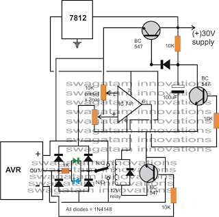
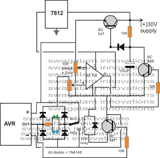
The circuit diagram of the proposed automatic voltage regulator (AVR) analyzer circuit is shown below:
When the input 30V power supply is switched ON, the 100uF capacitor slowly starts charging up producing a gradual increase of voltage at the base of the transistor which is configured as an emitter follower.
In response to this ramping voltage, the emitter of the transistor also generates a correspondingly increasing voltage from 0 towards 30V. This voltage is applied to the connected AVR.
In case the AVR is PNP, it's output produces a positive voltage which triggers the corresponding transistor, which in turn activates the attached relay.
The relay contacts instantly connects the appropriate polarity to the bridge network such that the ramping voltage from the bridge output is able to reach the opamps relevant input.
The above action also illuminates relevant LED for the required indications.
The opamp presets are adjusted such that as long as the output ramp stays slightly below than the input ramp, the opamp output stays at zero potential.
As per the internal setting of the AVR, its output would stops rising above a certain voltage, say at 14.4V, however since the input ramp would continue and tend to rise above this value, the opamp would instantly change its output state to positive.
With the above conditions the positive from the opamp fed to the shown transistor stage grounds the base of the ramp generator transistor, switching it OFF instantly.
However, during the above switching OFF procedure, the opamp quickly reverts to its original state bringing the circuit back to its previous state and the voltage appears to be latched at the AVR constant output.
The DVM must be connected across emitter of the top transistor and the common ground.
The 7812 IC is positioned for providing regulated voltage to the relay and the IC.

