In cars or automobiles, LEDs have grown to be the preferred choice of lighting. Whether it's the rear tail-lights or the tell-tale indicators in the cluster as indicated in Figure 1 below, all incorporate LEDs nowadays. Their compact dimensions helps versatility in design and offers the prospective to be as durable as the vehicle’s life expectancy itself.


You may also want to learn how to design Customized LED Drivers for your Home
On the other hand, even though LEDs are highly efficient devices, they are vulnerable to deterioration from unregulated voltage, current and temperature parameters, particularly in the harsh automotive ecosystem.
To be able to enhance LED light efficiency and permanence, LED driver circuit design demands cautious analysis.
Electronic circuits that are applied as LED drivers fundamentally make use of transistors. One standard circuit topology frequently used in LED drivers happens to be the linear topology, where the transistor is designed to work inside the linear region.
This topology gives us the option of making driver circuits through transistors only or using specialized ICs with built-in transistors and additional LED enhancement features.
In discrete applications, bipolar junction transistors (BJTs), which are highly accessible commodity products, tend to be the favorite.
Despite the fact that BJTs are simple to configure from a circuit point of view, major complications can be found while creating a total LED driver solution that fulfills current control accuracy, PCB dimension, heat management and fault diagnosis, which are a few important prerequisites throughout the entire working supply voltage and temperature range.
Furthermore, as the quantity of LEDs increases, circuit design using discrete BJT stages get even more sophisticated.
Compared to discrete parts, applying IC based alternatives seem to be more convenient with respect the circuit layout, but additionally the design and evaluation procedures.
Besides that, the general remedy may perhaps be even more affordable.
Parameters for Designing Automotive LED Drivers
Therefore, when designing LED driver circuits for an automotive lighting application, it is essential to contemplate LED focal points, evaluate circuit design alternatives, and factors in system demands.
An LED is actually a P-type N-type (PN) junction diode which allows the current to move through it only in a single direction. Current begins flowing as soon as the voltage across the LED reaches the minimum forward voltage (VF).
The level of illumination or the brightness of an LED is determined by the forward current (IF ); while how much current an LED consumes depends on the voltage applied across the LED.
Even though the LED brightness and the forward current IF are linearly related, even a slight increase in the forward voltage VF across the LED can trigger an rapid escalation in the current intake of the LED.
LEDs with different color specifications have different VF and IF specifications due to their specific semiconductor ingredients (Figure 2). It is necessary to consider each LED’s datasheet specs into account, specifically while applying different color LEDs within the a single circuit.
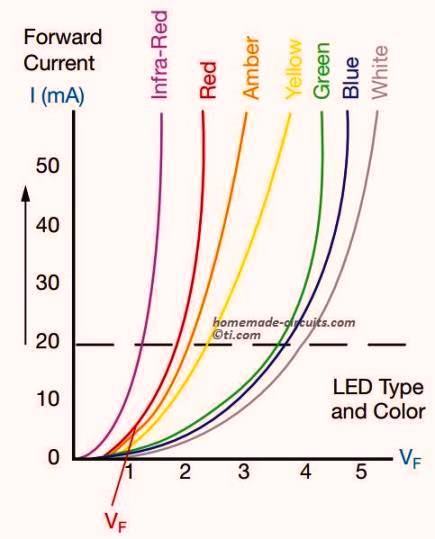
For instance, when developing with red-green-blue (RGB) lighting, a red LED may come with a Forward voltage rating of around 2 V, while the same for a blue and green LEDs could be around 3 to 4 V.
Considering that you’re operating these LEDs from a single common voltage supply, you might need a well calculated current-limiting resistor for each of the colored LEDs, to avoid LED deterioration.
Thermal and power efficiency
Apart from supply voltage and current parameters, temperature and power efficiency likewise demand careful analysis. Although, most of the current applied across an LED is converted into LED light, a small amount of power is turned into heat within the PN junction of the device.
The temperature generated across an LED junction could be seriously affected by a few external parameters such as:
- by the atmospheric temperature (TA),
- by the thermal resistance between the LED junction and ambient air (RθJA),
- and by the power dissipation (PD).
The following Equation 1 reveals the power dissipation spec PD of an LED:
PD =VF × IF ------------ Eq #1
With the help of the above, we can further derive the following equation that calculates the junction temperature (TJ ) of an LED:
TJ = TA + RθJA × PD ---------- Eq #2
It is essential to determine the TJ not just under normal working conditions, but also under an absolute maximum ambient temperature TA of the design, with regard to worst-case-scenario concerns.
As the LED junction temperature TJ increases, its work efficiency deteriorates. An LED’s forward current IF and junction temperature TJ must stay below their absolute maximum ratings, as classified by the datasheets, so as to protect against destruction (Figure 3).
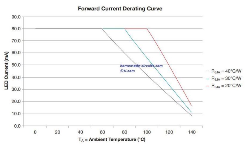
Besides the LEDs, you should also take into account the power efficiency of resistors and the driving elements such as BJTs and operational amplifiers (op amps), specifically as the amount of discrete components increases.
Inadequate power efficiency of the driver stages, the LED on-time period and/or the ambient temperature all of these factors may lead to a rise in temperature of the device, influencing the BJT driver's current output, and reducing the VF drop of the LEDs.
As the rise in temperature reduces the LEDs forward voltage drop, the LED's current consumption rate rises; leading to a proportionately increased power dissipation PD and temperature, and this causes further reduction in LED's forward voltage drop VF.
This cycle of a continuous rise in temperature, also referred to as “thermal runaway,” forces the LEDs to function above their optimum operating temperature, causing rapid degradation, and at some point failure of the device, because of an increased level of IF consumption.
Linear LED Drivers
Operating LEDs linearly through either transistors or ICs is actually quite convenient. Of all possibilities, the most simple approach to control an LED is usually to connect it right across the supply voltage source (VS).
Having the right current-limiting resistor restricts the current draw of the device and fixes an accurate voltage drop for the LED. The following Equation 3 can be used for working out the series resistor (RS) value:
RS = VS - VF / IF ---------- Eq #3
Referring to Figure #4 we see that 3 LEDs are used in series, the entire voltage drop VF across the 3 LEDs should be taken into consideration by the VF calculation (the LED's forward current IF remains constant.)
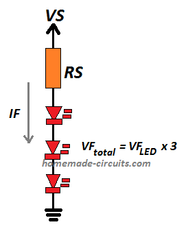
Although this can be the simplest LED driver configuration, it may be quite unpractical in a real-life implementation.
Power supplies, particularly automotive batteries, are susceptible to voltage fluctuations.
A minor increase in the supply input triggers the LED to draw higher amounts of current and consequently get destroyed.
Furthermore, excessive power dissipation PD in the resistor increases the device temperature, which may give rise to thermal runaway.
Discrete Constant-Current LED Drivers for Automotive Application
When a constant current feature is used, it ensures an enhanced power-efficient and reliable layout. Since the most prevalent technique to operate an LED is through an on and off switching, a transistor enables a well regulated current supply.
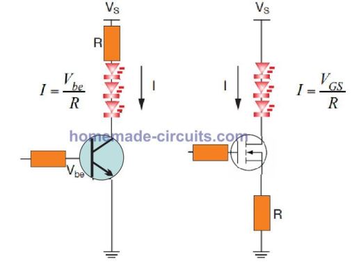
Referring to the Figure 5 above, it may be possible to go for either a BJT or a MOSFET, based upon on the voltage and current specifications of the LED configuration. Transistors easily handles larger power compared to a resistor, yet are susceptible to voltage ups and downs and temperature variations. For example, when the voltage around a BJT rises, its current also proportionately increases.
To guarantee additional stability, it is possible to customize these BJT or MOSFET circuits to deliver constant current despite having imbalances in the supply voltage.
Designing LED Current Source
Figures 6 to 8 demonstrate a handful of current-source circuit illustrations.
In Figure 6, a Zener diode generates a stable output voltage into the base of the transistor.
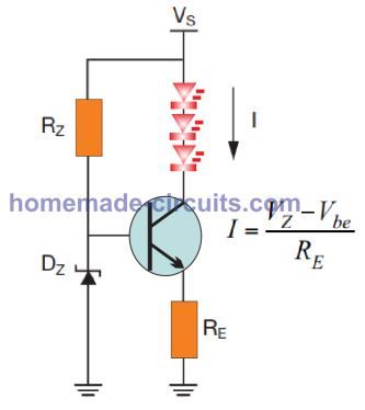
Current-limiting resistor RZ ensures a controlled current to enable the Zener diode to work correctly.
The Zener diode output produces a constant voltage despite of fluctuations in the supply voltage.
The voltage drop over emitter resistor RE should complement the voltage drop of the Zener diode, therefore the transistor adjusts the collector current; which ensures that the current through the LEDs always remains constant.
Using an Op Amp Feedback
In Figure 7 below, an op amp circuit with a feedback loop is shown for making an ideal automotive LED controller circuit. The feedback connection ensures that the output gets automatically adjusted in order that the potential developed at its negative input remains equal to its positive reference input.
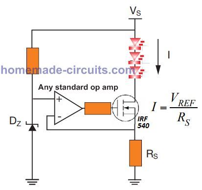
A Zener diode is clamped to generate a reference voltage at the non-inverting input of the op amp. In case the LEDs current exceeds a predetermined value, it develops an proportionate amount of voltage across the sense resistor RS, which tries to surpass the zener reference value.
Since this causes the voltage at the negative inverting input of the op amp to exceed the positive reference zener value, forces the op amp output to switches OFF which in turn reduces the LED current and also the voltage across RS.
This situation again reverts the op amp output to switch ON state and activates the LED, and this self adjusting action of the op amp continues infinitely ensuring that the LED current never exceeds the calculated unsafe level.
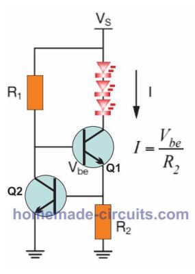
Figure 8 above illustrates one more feedback based design accomplished using a a couple of BJTs. Here, the current flows by means of R1 , switching ON transistor Q1 . The current continues travelling via R2 , which fixes the correct amount of current through the LEDs.
In case this LED current through R2 tries to exceed the predetermined value, the voltage drop across R2 also increases proportionately. The moment this voltage drop rises up to the base-to-emitter voltage (Vbe) of transistor Q2 , Q2 begins turning ON.
Being switched ON Q2 now starts drawing current through R1 , forcing Q1 to begin turning off and the condition keeps self adjusting the current through the LED ensuring the that the LED current never goes beyond the unsafe level..
This transistorized current limiter with feedback loop guarantees a constant current supply to the LEDs as per the calculated value of R2. In the above example BJTs are implemented but nevertheless it is also feasible to use MOSFETs in this circuit, for higher current applications.
Constant Current LED Drivers using Integrated Circuits
These essential transistor based building blocks, could be easily replicated to operate several strings of LED, as displayed in Figure 9.
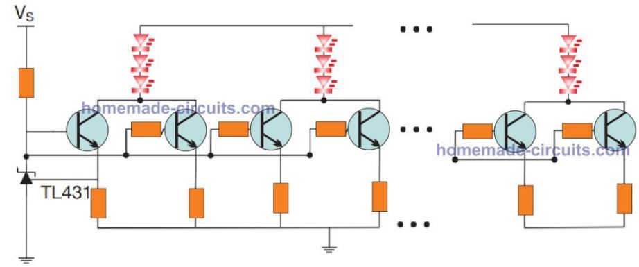
Controlling a group of LED strings quickly causes the component count to rise, occupying higher PCB space and consuming more number of general-purpose input/output (GPIO) pins.
Moreover, such designs are basically without brightness control and fault diagnostics considerations, which are essential needs for most power LED applications.
For including the specifications like brightness control and fault diagnostics requires additional number of discrete components and added design analysis procedures.
LED designs which include higher number of LEDs, causes discrete circuit designs to include higher number of parts, increasing the complexity of the circuit.
In order to streamline the design process, it is considered most effective to apply specialized ICs to function as LED drivers. Many of discrete components as indicated in Figure 9 could be made easier with an IC based LED driver as revealed in Figure 10.
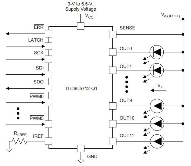
LED driver ICs are specially designed for tackling critical voltage, current and temperature specifications of LEDs, and also for minimizing the part count and board dimensions.
Furthermore, LED driver ICs may have additional features for brightness control and diagnostics, including over temperature protection. That said, it may be possible to achieve the above advanced features using discrete BJT based designs also, but ICs seem to be an easier alternative, comparatively.
Challenges in Automotive LED Applications
In many automotive LED implementation, brightness control becomes an esential necessity.
Since adjusting the forward current IF through the LED adjusts the brightness level proportionately, analogue designs can be employed for achieving the results. A digital method of LED brightness control is through PWM or pulse width modulation. The following details analyzes the two concepts and shows how they can be applied for automotive LED applications
Difference Between Analogue and PWM LED Brightness Control
Figure 11 evaluates the main difference between analogue and digital methods of controlling LED brightness.

By using analog LED brightness control, the LED illumination is altered through the magnitude of the flowing current; larger current results in increased brightness and vice versa.
But, the quality of analog dimming or brightness control is not satisfactory, specifically at lower brightness ranges. Analog dimming is usually not appropriate for color dependent LED applications, like RGB lighting or status indicators; since varying IF tends to affect the color output of the LED, causing poor color resolution from the RGB LEDs.
In contrast, PWM based LED dimmers do not vary the LED forward current IF, rather controls the intensity by varying the ON/OFF switching rate the LEDs. Then, the average ON time LED current decides the proportionate brightness on the LED. It is also called the duty cycle (the ratio of pulse width over the pulse interval of the PWM). Through PWM, a higher duty cycle results in a higher average current through the LED causing higher brightness and vice versa.
Due to the fact that you are able to finely tweak the duty cycle to various illumination ranges, PWM dimming helps to achieve a much wider dimming ratio in comparison to analog dimming.
Although PWM guarantees an enhanced brightness control output, it necessitates more design analysis. The PWM frequency has to be a lot higher than what our vision can perceive, otherwise the LEDs may end up appearing like they are flickering. Furthermore, PWM dimmer circuits are notorious for generating electromagnetic interference (EMI).
Interference from LED Drivers
An automotive LED driver circuit built with inadequate EMI control might adversely affect other neighboring electronic softwares, such as generation of buzzing noise in radio or similar sensitive audio equipment.
LED driver ICs can certainly provide you with both analog and PWM dimming features along with supplemental functions to tackle EMI, such as programmable slew rate, or output channel phase-shift or group delay.
LED diagnostics and fault reporting
LED diagnostics which includes over-heating, short-circuit or open circuit are a popular design prerequisite, particularly when the application demands multiple LED operation. Minimizing the risk of LED malfunction, LED drivers feature regulated output current with greater precision than transistor based discrete driver topolgies.
Along with this, IC drivers additionally incorporate over-temperature protection to ensure higher operational life expectancy of the LEDs and the driver circuit itself.
LED drivers designed for automobiles must be equipped to detect errors, for example an LED open or short circuit. A few applications might also necessitate followup measures to counter a detected fault.
As an example, a car rear light module includes a number of strings of LEDs to illuminate tail lights and brake lights. In the event that a busted LED fault is detected in one of the LED strings, then the circuit must be able to switch off the entire array of LEDs, so as to ensure that further damage to the remaining LEDs can be avoided.
The action would also warn the user regarding the non-standard degraded LED module which needs to be uninstalled and sent for maintenance to the manufacturer.
Body Control Modules (BCM)
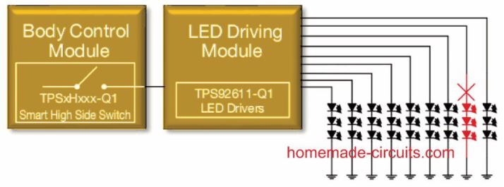
To be able to provide a diagnostics alert to the car user, an intelligent high-side switch in the body control module (BCM) registers a fault through the rear-light element as illustrated in the above Figure 12.
Having said that, identification of an LED fault through the BCM could be complicated. Occasionally you may use the same BCM board design to detect a standard incandescent bulb-based circuitry or an LED-based system; because LED current tend to be substantially smaller as opposed to incandescent bulb consumption, differentiating between a logical LED load.
Conclusion
An open or disconnected load could be difficult to identify if the current-sense diagnostics are not designed accurately. Instead of having an individual open LED string, switching OFF the entire string of LEDs strings becomes more easily detectable for the BCM for reporting an open load situation. A condition that ensures that if One-LED-fail then All-LED-fail criterion could be executed to shut down all the LEDs on detecting a single LED fault. Automotive linear LED drivers include the feature that allows a one-fail-all-fail reaction and can identify a common error bus throughout multiple ICs configurations.
Original Source: ti.com
Did you just paraphrase “Fundamentals to automotive LED driver circuits” white paper by Texas Instruments without crediting them or you wrote it for them and just retold it for you blog? lol
Actually it says Kathrina Macalanda in their document.
I did not paraphrase it. I wrote it by understanding the content.
I have also given the necessary credit at the end of the post.
Sir,
Sorry I used google translate.
I have a specification LED:
Voltage 9-12 Volt.
Current 5 Ampere.
Output 40-60 watts.
I plan to use it for the car.
How is the driver circuit so that it can be used for 2 modes?
If the low beam output is 40 watts and the high beam is 50 watts?
Thank you for the help.
No problem Heru, you can try the opamp based circuit, and put a selector switch for the dipper operation, as shown in the following modified diagram:
….the red LEDs can be replaced with your 12V LED
Sir, Thanks for the response.
Apart from this scheme, is it possible and or more effective to use a relay, and if possible, what is the scheme?
I’ve seen flashlights that can be adjusted in brightness by using a step up and using a potentiometer.
Now I think that a relay and 2 buttons (low beam and high beam trigger) can replace it, but sorry I don’t understand the scheme.
Can you help?
Thank you.
Hero, you can use the following set reset circuit with relay. The relay contacts can be simply replaced with the points that is shown for the SPDT switch in the previous diagram. You can see the small three circles of the switch, you will have to replace those 3 circles with the 3 relay contacts as given in the following set reset circuit:
Make this Simple Set Reset Circuit using IC 555
Thankyou Sir.
Hi there-
I’m struggling to find an elegant solution to control a 12VDC automotive-style relay with a PWM circuit. The problem I have is that a control system for turning LEDs on/off, which was previously just a smart relay, is now a solid-state LED driver with PWM dimming (300Hz). Some of the outputs need to be switching a relay, so the PWM presents a problem. The outputs are ganged together, so I cannot simply make one of them run 100% duty cycle to power the relay coil. The duty cycle is 20%-100%, and I’d like the relay to close at anything 20% or higher. Most automotive relays are not spec’d to hold below about 8-9V and not designed for a pulsed input. Are there any ideas here for a simple power supply, delay timer, etc. that would allow a digital output to be synthesized on a PWM LED controller output? Thanks!
It looks difficult to me, since PWM cannot be converted to an average DC through ordinary means, due to its peak levels which are always equal to the supply voltage.
However, you can try implementing the following technique, it seems it might just work. It employs an LDR/LED based opto coupler for the main processing:
Hi Swag
Thanks for your time and effort. Greatly appreciated. I will give it a go.
Best regards
Piet
Thanks Piet! Glad to help!
Thank you for this interesting and informative article.
A lot of people with vintage cars/ motorbikes have problems with insufficient power supplies and are looking for simple solutions to save current. But they want to keep the cabling as is and are only interested in replacing bulbs with alike looking LEDs and maybe some hidden electronics to power the LEDs safely.
So it would be nice for DIY to talk about High Side circuits as most of todays cars and motorbikes come with GND as standard fixed pole for lamps – so most of the above circuits only can be done by having to get a second cable to the LEDs and make sure that the original earth connection is removed and isolated.
Keep on your good job.
Kind regards from Germany
Raimund
Thank you for visiting this site, and appreciate your valuable feedback.
Hi Swag
Firstly, thanks for your informative topics.
I would like a circuit design to dim 2x 18w, 12volt led spotlights in a 4×4 bumper as it is connected to the park lights and too bright for oncoming vehicles.
My idea is to let them work via the dimmer with preset brightness with the park/dim setting, and when the brights are on, the dimmer is then bypassed.
I presume it will be a constant current circuit.
Thank you for your help.
Best regards
Piet Louwrens
Thanks Piet, you can try the following circuit:
You can bypass the MOSFeT drain source points for bypassing the dimmer effect
Rx = 0.6 / LED current
Hi Swag
Thank you so much for your quick response. I will give it a go and let you know how it works for me.
Best regards
Piet
No problem Piet!
Hi Swag
Regarding Rx, the two leds is 3A, 36Watt total. Please calculate the value for me, as well as the wattage thereof.
These circuits work with smoke and once the smoke is released, they work no more 🙂
Thank you so much.
Best regards
Piet
Hi Piet, The value of Rx will be;
Rx = 0.6 / 3 = 0.2 ohms 3 watt
Hi swag
Much appreciated, that is what I had too.
Best regards
Piet
You are most welcome Piet
Hi Swag
I built the circuit and it does dim the 2x 1,5Amp leds but only slightly.
Any suggestions why that would be?
Thanks
Best regards
Piet
Hi Piet, If the pin3 PWM is varying correctly then the LED has to dim fully in response to the pot adjustments. You can check the DC voltage output at pin3 with a meter, you will find the reading varying from 0 to 100%. If it doesn’t then your IC 555 or the circuit may be having issues. If it does, then the LED module could be having an internal filter capacitor which may not be allowing the dimming process. You may then try using any other discrete LED with a 1k resistor in series
Hi Swag
Thanks for your response.
Will check the conditions as you mentioned.
Best regards
Piet
No problem Piet!
This is by no means as technical so I hope it’s ok but I am going to have to replace a 60 LED “UHP” angel eye and voltage step down box/regulator. (the box was destroyed from water damage and I inadvertently applied 12v directly to one of the angel eyes so it’s toast too.) I’ve seen some off the shelf boxes that step from 12v to 5v 3A 15W. I’m still just gathering information because the manufacturer isn’t being helpful unless I buy all new ones and the board is so toasted it’s hard to tell whats what but in general is 5v too much? I’m trying to match the brightness as best as possible (as well as color temp.) so I’m guessing the originals leaned more to brightness (they are bright even during the day) over longevity to a certain degree. I don’t want to overdue it or come up short. Again, this is probably pretty basic for you so I appreciate any general guidance since I’m looking for a more off the shelf solution. The originals are Depo Angels Eyes for an E90.
If you are looking for an universal step down converter circuit, then probably you can try the following proven design:
https://www.homemade-circuits.com/5v-pwm-solar-battery-charger-circuit/
However, to make this successfully it may be necessary to have a good knowledge and experience in the field of electronics.
Passion the site– very individual friendly and lots to see!
Hi Swag
I have a new challenge for you.
These days cars have harnesses for the trailer light plug with a sealed component box that controls ( I think) power for indicators etc.
Do you perhaps know what it consists of and what purpose it serves as I need to make up a harness to supply with my rear replacement bumpers for 4x4s
Thank you
Best regards
Hi Piet, sorry I have no idea about it! unless I know the exact function of the unit inside the box!
Hi Swag
It seems that this controller accepts the signals from the vehicle (indicators etc) and then uses a fused 12v input to power the trailer lights so that the trailer cant interfere with the vehicles setup.
Hope it makes sense.
Thanks
Best regards
Piet
Hi Piet, do you mean the circuit in the box isolates the trailer lights from the vehicle electrical, what can be the reason for that? That could be perhaps implemented through an opto coupler
Hi Swag
I think you nailed it !
It would be the two indicators, park and brake.
Please if you could design a circuit for this purpose.
Thanks so much for your help.
Best regards
Piet
Thanks Piet, do you want all these lamps to be isolated from the vehicle electrical and from each other also? Still can’t figure out why this may be necessary in any vehicle?
Swag, one more thing, the vehicle and trailer share negative if it wound make a difference .
Thanks
Piet
Hi Swag
I got this off google:
“They do it this way so that there is no interference with the CAN bus of the car, and to ensure no warranty issues because of cut wires”.
The four circuits will share common earth so there will be four positives from the different signals, one from each input and a fused positive will feed each output circuit to the trailer.
Hope this help.
Thanks
Best regards
Piet
Thank you Piet,
The following design is probably the only way the intended loads could be prevented from interfering with other sensitive electronics in the vehicle:
The +12V line has to directly connect with the battery (+) terminal, while the ground line has to connect with the body chassis of the vehivle.
You may have to repeat the same design for each of the desired lamps