This fascinating Automotive Sensor Monitor Circuit was created and shared with me for publication by a devoted reader of this blog and passionate electronics enthusiast, Mr. August Peterson. I sincerely appreciate Mr. August's valuable and generous contribution to this site.
Overview
Automotive diagnostic code readers are invaluable in displaying what the vehicle electronic control unit is receiving.
What these devices cannot detect are defects in the wiring, electrical connections and mechanical integrity of the sensors.
I developed the sensor monitor to display the actual voltages available at the sensor connections in real time.
Connection to the sensor plug was made by inserting thin probes between the seal and the wire until in connected with the contacts in the plug.
"Back Entry" connection was preferred to piercing the wires which would lead to moisture ingress and wire corrosion.
The device can monitor all passive sensors including one type of oxygen sensor but not inductive sensors with a.c. output.
A sound knowledge of generic sensor output is required to evaluate the results produced by this instrument.
The value in this instrument is that you can confirm a defective sensor before replacing it or confirm a wiring or connection problem that the code reader detects as a sensor failure!
Operating Manual
This Automotive Sensor Monitor circuit should be used in conjunction with the operating instructions by a person qualified in electronic automotive repairs and diagnostics.
Warning: We (or any of our representatives) are not liable for any consequential losses, damages or injuries (to personnel or any third parties) whatsoever, whether direct or indirect, irrespective of cause or nature, relating to the application or use of any of the information or data provided by us, or the use of the Automotive Sensor Monitor.
Features
Capable of monitoring the zirconium dioxide (0 to 1 volt) oxygen sensor and general sensors with outputs in the 0 to 5 volt range.
It monitors the signal that the vehicle ECU is receiving, which means that for voltage divider sensors, the inter-connecting wiring circuit is being checked at the same time.
The Automotive Sensor Monitor has no internal battery. It should be powered from the vehicle 12 volt or 24 volt battery system and will not be affected by voltage fluctuation.
The Automotive Sensor Monitor is fitted with reverse polarity protection to protect it against accidental reverse connection to the battery.
It is also protected against being connected to a sensor with the switch in the incorrect position, this will not damage the unit or the system being monitored.
The Automotive Sensor Monitor can read out the signals from the Oxygen sensor, dynamic earth connection, Throttle potentiometer, Air flow meter, Air mass meter, Throttle switch, Engine temperature sensor, Air temperature sensor, Manifold pressure sensor and Turbo pressure sensor.
It cannot read out: inductive sensors, hall sensors, knock sensors, rotational sensors or air bag sensors.
The Automotive Sensor Monitor can be connected to a system and the vehicle driven so that the signal can be monitored in operation.
Circuit Diagram

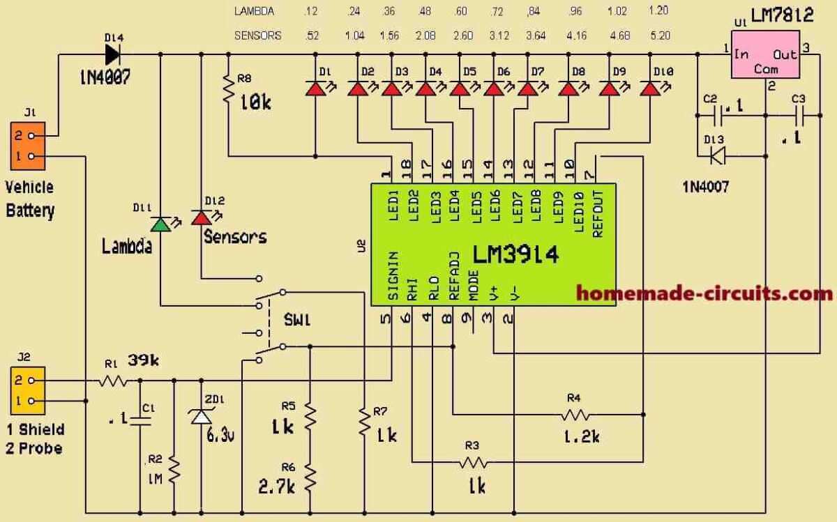
Understanding the Circuit Stages
Section on Power Supply:
A car battery connected at J1 powers the circuit.
Through the use of capacitors C2 and C3, the 7812 voltage regulator (U1) filters noise and maintains a constant 12V supply.
The circuit is shielded from reverse polarity and vehicle voltage spikes by diodes D13 and D14.
Section of Input:
The shield and probe terminals (J2) are where the sensors are linked.
The following conditions the input signal:
R1 and C1 for signal stabilization and filtering.
Zener diode (Z1), which makes sure the voltage stays below 6.3V.
R5, R6, and R7 voltage dividers to properly scale the input signal.
Choosing a Mode:
By using the SW1 toggle switch, the user can observe either:
Lambda sensor (this mode is shown by the green LED D11).
Additional sensors (this mode is shown by the red LED D12).
LM3914 Signal Processing:
The voltage level of the sensor is shown on a bar graph of LEDs (D1 to D10) by the LM3914 (U2).
How it operates:
The SIGNIN (pin 5) receives the input signal.
RHI (pin 6) and RLO (pin 4) establish the voltage range for the display, while R2 and R3 control the scale.
The voltage is transformed into an LED bar display by the LM3914, where:
For the lowest voltage, D1 illuminates.
For the highest voltage, D10 illuminates.
The IC is in "bar mode" when the MODE (pin 9) is grounded, causing all of the LEDs to illuminate in turn according to the voltage.
LED Signals:
The output voltage of the sensor is shown visually in the LED bar graph (D1–D10).
The activity or state of the sensor is clearly shown by the additional LEDs that light up when the input voltage rises.
Features of Protection:
The circuit is shielded from reverse current and voltage spikes by diodes D13 and D14.
By clamping excessive voltage, the Zener diode (Z1) protects the LM3914 and other parts.
Useful Applications:
Numerous automobile sensors may be monitored using this circuit, including:
- Lambda (oxygen) sensors.
- sensors with analog outputs for temperature, pressure, etc.
It offers a straightforward yet efficient method of visualizing sensor performance in real time.
Connecting to the vehicle system
The sensor monitor uses the same battery negative connection as the vehicle battery.
The Automotive Sensor Monitor should be connected to the vehicle battery or other convenient positive and negative connection. One of the Scale Indicators will illuminate to indicate that the unit is powered up.
The Signal of the Automotive Sensor Monitor should be connected to the vehicle sensor that you wish to monitor.
The signal must be picked up from the back of the sensor connector while the sensor is connected to the vehicle harness. Do not unplug the sensor from the vehicle system.
When the red probe is connected to sensor output signal – the signal display will respond to variations as the sensor operates.
Using the Selector Switch, select either Lambda or Sensors, depending upon which sensor you wish to monitor. As the selector switch position is changed, the Scale Indicators will illuminate to indicate which scale is applicable for the required read out.
The vehicle can now be switched on or started, and the signal from the sensor observed on the LED readout.
The Automotive Sensor Monitor can be connected to a vehicle earth wire, any voltage drop during operation of the system can be observed. The Selector switch should be switched to the Lambda position for this evaluation.
The Automotive Sensor Monitor does not interfere with the signal to the vehicle ECU, therefore it should be invisible to the vehicle system, and the vehicle can be driven while observing the performance of the sensor.
Interpreting the Lambda results
Output from the Oxygen sensor is not valid until the engine and exhaust are up to operating temperature and the engine is running at about 2000 rpm.
Only the zirconium dioxide type that generates a 0 to 1 volt signal can be monitored.
The read out is evaluated as follows:-
- An oscillating reading on the left (lower) half of the lambda scale indicates a lean fuel mixture.
- An oscillating reading on the right (upper) half of the lambda scale indicates a rich fuel mixture.
- An oscillating reading in the centre section of the lambda scale indicates a good fuel mixture.
- An oscillating reading across any 3 of the lambda scale LED’s indicates a failing Oxygen sensor.
- An oscillating reading across any 2 of the lambda scale LED’s indicates an Oxygen sensor failure.
- A fixed reading on one of the LED’s of the lambda scale indicates an Oxygen sensor failure.
- A fixed reading on one LED (± 0.48v) reflects an open circuit of the lambda sensor, or the system is operating in open loop mode.
Interpreting dynamic earth results
Earth connections that are transferred to injectors and other fast acting actuators through the vehicle ECU are normally difficult to test.
This is because they only fail during the activation of the actuator which is normally for a very short duration (between 4 and 20 milliseconds).
The read out is evaluated as follows:-
- Any LED that illuminates indicates a defective earth connection.
- Any LED that flickers indicates a defective earth connection.
- If no LED’s illuminate or flicker it indicates that there is no voltage drop across the earth connection and no problem present.
Note: The switch should be in the Lambda position for this test.
Interpreting General Sensor results
Only sensors of the 0 to 5 volt output types can be monitored. Certain manufacturers use sensors that operate within the range of 4.5 to 9 volts, these cannot be reliably monitored using the Automotive Sensor Monitor.
Sensor monitoring:
General sensors operate in the range of 0.5 volts to 4.5 volts. Normally the fail safe voltage is the 0.5v potential and the full operating point is the 4.5v potential.
The indicators should illuminate steadily and progressively throughout the range. If they fluctuate rapidly toward 0.5v or 5v this denotes an internal break in the continuity of the sensor.
Examples of sensor readings are:
- Throttle potentiometer at idle should read about 1 volt and at full open position it should read up to 4.5 volts.
- Air mass meter should provide similar results to the throttle potentiometer. Note that the inability for the sensor to reach the higher voltage at full load delivery indicates a contaminated sensor that cannot “see” all of the air that is being drawn into the engine.
- The engine temperature sensor should read up to 4.5 volts when cold and about 1 volt when hot. Note that the read out indicators should be observed throughout the warm up phase in case the sensor goes open circuit during the warm up phase.
- The manifold air pressure sensor and turbo pressure sensor should fluctuate between 0.5 volt and 4.5 volt dependent on the pressure in the manifold.
Need Help? Please Leave a Comment! We value your input—Kindly keep it relevant to the above topic!