

This article explains an original Automotive Trailer Interface Circuit, a testament to the creativity of our reader Mr. August Peterson, an avid electronics devotee. We are honored to share his design and express our sincere thanks for his contribution to our platform.
Overview
Modern vehicles have load sensing on their rear lights to detect faults and bulb failure.
If a trailer plug is wired to these vehicles it will reflect as a fault on the vehicle or worse still, cause damage to the vehicle electronics.
The solution is an interface that is not detected by the load sensing but will still activate the trailer lights as required.
This circuit will do just that, by transferring power from the battery to the trailer lights via relays.
The vehicle must have separate stop and tail lamp filaments in the rear lights.
This circuit will not work with the vehicles that use PWM on their stop / tail light bulbs.
PWM stop / tail configuration is where one filament is used and a long pulse represents stop light and a short pulse represents tail light.
There is no easy single solution interface for PWM rear lights because each manufacturer uses a unique frequency and pulse width for stop & tail light activation.
Circuit Diagram
How it works:-
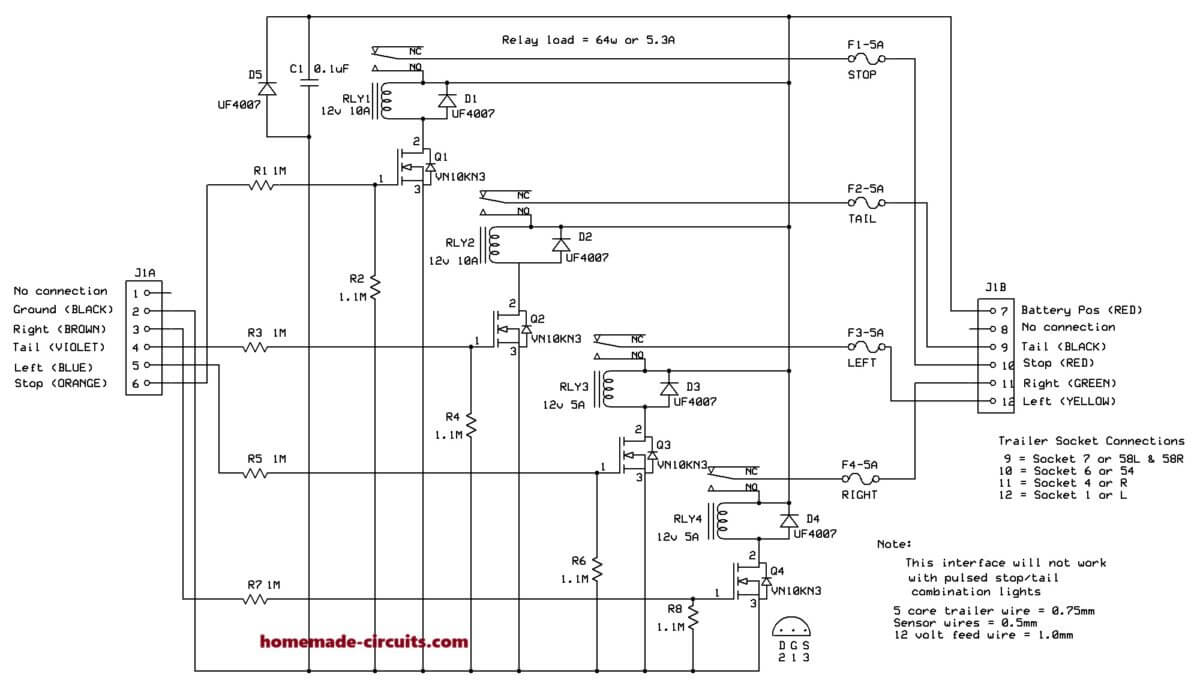
Wiring from the vehicle rear light circuits is extended and connected to the respective pins of J1A. (Ground, R Indicator, Tail light, L Indicator and Stop Light)
The ground wire should be at least 1mm because it will carry the load of this circuit and the load presented by the trailer lights.
Each input has a 1M resistor in series with a MOSFET Gate to create a high resistance so as not to load the vehicle system.
The Gate has a 1.1M resistor to ground to prevent the MOSFET from remaining in conducting mode after the input bias has been removed.
When the respective MOSFET is biased, it pulls in the relay. The contacts of the relay connect the vehicle battery to the respective trailer light through a 5A fuse and the respective pin of J1B.
The load of the trailer lights is therefore not detected by the vehicle rear light system. Connector J1B/7 should be connected to a fuseable connection on the vehicle that becomes live when the ignition is turned on. J1B/9,10,11&12 must be connected to the respective trailer lights.
Parts List (BOM)
| Component | Value/Part Number | Description |
|---|---|---|
| Resistors | ||
| R1, R3, R5, R7 | 1MΩ | 1/4W Resistor |
| R2, R4, R6, R8 | 1.1MΩ | 1/4W Resistor |
| Capacitor | ||
| C1 | 0.1µF | Ceramic Capacitor |
| Diodes | ||
| D1, D2, D3, D4, D5 | UF4007 | Ultra-fast Recovery Diode |
| Transistors | ||
| Q1, Q2, Q3, Q4 | VN10KN3 | N-channel MOSFET |
| Relays | ||
| RLY1, RLY2 | 12V 10A | SPDT Relay |
| RLY3, RLY4 | 12V 5A | SPDT Relay |
| Fuses | ||
| F1 | 5A | Blade Fuse (STOP) |
| F2 | 5A | Blade Fuse (TAIL) |
| F3 | 5A | Blade Fuse (LEFT) |
| F4 | 5A | Blade Fuse (RIGHT) |
| Connectors | ||
| J1A | - | Input Connector |
| J1B | - | Output Connector (Trailer Socket) |