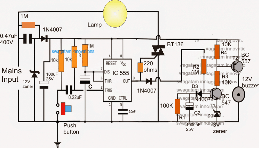
The simple bathroom lamp timer circuit features a delay OFF timer which switches OFF the triggered lamp after a set predetermined time delay, additionally the circuit also includes a delay ON timer circuit which is appropriately set such that a warning tone is generated a few seconds before the lamp is about to shut off. The idea was requested by Mr. Enrico.
Circuit Objectives and Requirements
- I want to make a bathroom light timer switch with IC555, but i want to add a warning alarm sound before the lights goes off when the time limit is reached, can you help me?
- Buzzer is DC type and lamp is fluorescent type...what i'm trying to do is to make it give a warning sound (somewhere about 15 seconds) before the timer switches the lamp off.
- The timer is adjustable from 1-10 minute.
Circuit Diagram

The Design
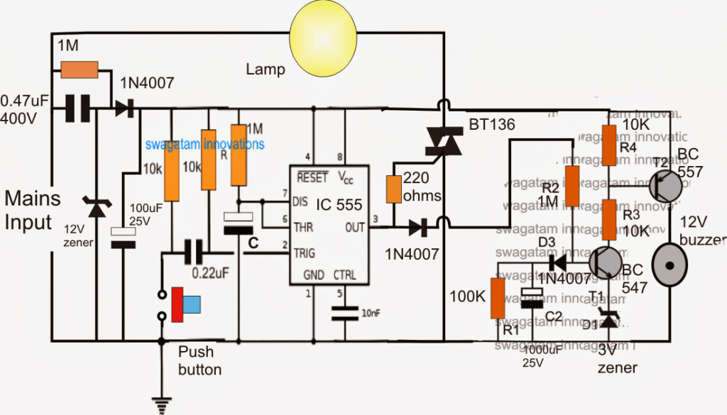
The proposed bathroom lamp timer with prior buzzer alarm circuit is built using a couple of monostable timer circuits, in the form of a IC 555 delay OFF and a transistor based delay ON timer, which are cascaded to function in a sequential manner.
When the timer circuit is powered, the lamp and the buzzer remain inactive however the circuit attains a standby mode.
As soon as the push button is pressed, the IC 555 monostable gets triggered, switching ON the triac and the lamp.
In the meantime, the transistor delay ON timer stage responds to the pin3 trigger of the IC 555 and begins counting, and the moment its set period is lapsed, the buzzer connected with it switches ON.
The above delay ON timer must be set such that it switches ON just before the lamp switches OFF at the desired timer interval.
This can be set with the help of R2 and C2, increasing these increases the delay ON period of the buzzer and vice versa.
For the IC 555 monostable, the time delay OFF for the lamp can be set by appropriately selecting the values of the capacitor C and/or the corresponding 1M resistor.
The entire circuit is powered through a transformerless power supply comprising of a 0.47uF/400 high voltage capacitor, and the associated 12V /1 watt zener and the 100uF/25V capacitor.
THE ENTIRE CIRCUIT IS NOT ISOLATED FROM MAINS AND THEREFORE MAY BE EXTREMELY DANGEROUS TO TOUCH IN SWITCHED ON CONDITION AND UNTIL NOT ENCLOSED INSIDE A SUITABLE INSULATED COVERING.
