A triac based battery charger replaces a normal relay for automatically cutting off power to the battery very efficiently.
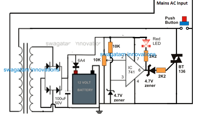
In this post I have explained a simple a battery charger circuit using a triac auto shut-off facility. The circuit can be used for charging any high current, high AH types battery with a full-charge auto cut-off feature.
The idea was requested by Mr. Rakesh Parmar.
Using Triac Instead of Relay
In one of the earlier posts I have explained a high current battery charger circuit based on a relay total shut off concept, which used a relay to initiate the charging process by switching ON the mains to the transformer and then shutting off the mains as soon as the full charge level was reached for the
battery.
In the proposed triac based battery charger circuit the operational principle is exactly similar except the incorporation of a triac instead of a relay.
Circuit Diagram

When mains power is applied the circuit does not switch ON by itself, and remains in a standby position.
The indicated push button is positioned for initiating the charging process, therefore as soon as this switch is pressed the triac ismomentarily shorted allowing the transformer to access the mains power
for that instant.
The above action also instantaneously allows the circuit to get powered for that particular period of time.
How it Works
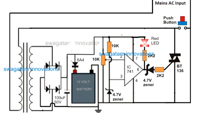
Assuming the battery to be in the discharged position, the above initialization causes a voltage to appear at pin#2 of the opamp at a level lower than the referenced pin#3 of the IC.
This in turn causes pin#6 of the opamp to go high, activating the triac and also latching the transformer in the powered position.
The entire circuit now gets latched and powered even after the switched is released, providing the required charging parameters to the battery. The red LED illuminates confirming the charging initialization of the battery.
As the battery gets charged, pin#2 potential gradually begins rising, until when finally it goes above the reference level of pin#3, which immediately prompts the output of the IC to go low. The moment this happens the triac gate trigger gets cut-off, breaking the latching action, and the entire circuit gets switched OFF.
The circuit returns to its previous standby position, until the next time when the switch is pushed again
for a new caging cycle.
If you liked this battery charger circuit using triac, please do share it with the others.
