

In this post I have explained about MOSFET bidirectional power switches, which can be used for operating a load across two points bidirectionally. This is simply done by connecting two N-channel, or P-channel MOSFETs back to back in series with the specified voltage line.

What is a Bidirectional Switch
A bidirectional power switch (BPS) is an active device built using MOSFETs or IGBTs, which allows a two way bidirectional flow of current when powered ON, and blocks a bidirectional flow of voltage when powered OFF.
Since it is able to conduct across both ways, a bidirectional switch can be compared and symbolized as a normal ON/OFF switch as shown below:

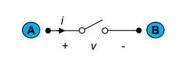
Here, we can see a positive voltage is applied at point "A" of the switch and a negative potential is applied at point "B", which allows the current to flow across "A" to "B". The action can be reversed by simply changing the voltage polarity. Meaning, the points "A" and "B" of the BPS can be used as interchangeable input/output terminals.
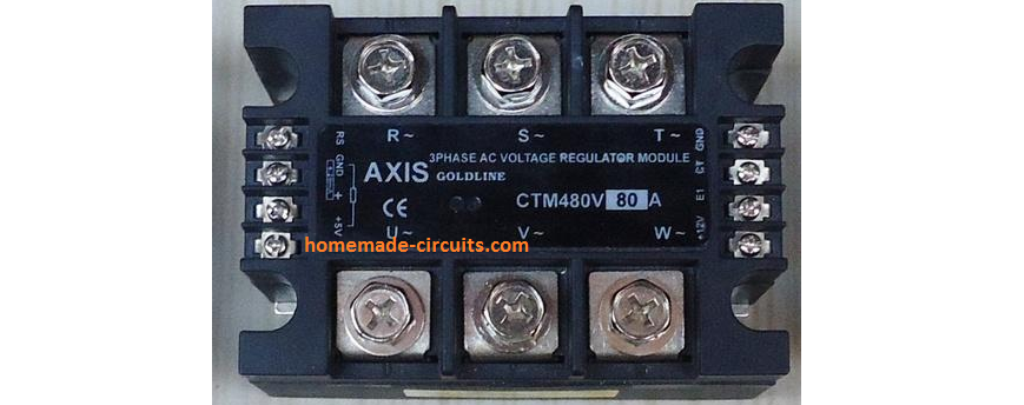
The best application example of a BPS can be seen in all MOSFET based commercial SSR designs.
Characteristics
In Power Electronics, the characteristics of a bidirectional switch (BPS) is defined as a four-quadrant switch having the ability to conduct positive or negative current in the ON-state, and also block positive or negative current in OFF-state. The four-quadrant ON/OFF diagram for a BPS is shown below.

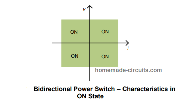
In the above diagram, the quadrants are indicated in green color which indicates the ON state of the devices regardless of the polarity of the supply current or the waveform.

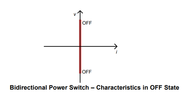
In the above diagram, the red straight line indicates that the BPS devices are in OFF state and offers absolutely no conduction regardless of the polarity of the voltage or the waveform.
Main Features a BPS Should Have
- A bidirectional switch device must be highly adaptable to enable easy and quick power conduction from both sides, that is across A to B and B to A.
- When used in DC application, a BPS must exhibit minimum on state resistance (Ron) for improved voltage regulation of the load.
- A BPS system must be equipped with proper protection circuitry to withstand sudden in rush current during a polarity change, or at relatively high ambient temperature conditions.
Bidirectional Switch Construction
A bidirectional switch is constructed by connecting MOSFETs or IGBTs back to back in series as shown in the following figures.
Here, we can witness three fundamental methods through which a bidirectional switch can be configured.

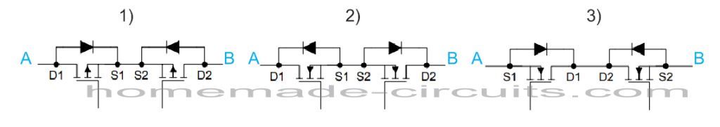
In the first diagram, two P-channel MOSFETs are configured with their sources connected back to back with each other.
In the second diagram, two N-channel MOSFETS can be seen connected across their sources for implementing a BPS design.
In the third configuration, two N-channel MOSFETs are shown attached drain to drain for executing the intended bidirectional conduction.
Basic Functioning Details
Let's take the example of the second configuration, in which the MOSFETs are joined with their sources back to back, let's imagine positive voltage is applied from "A", and negative to "B", as shown below:

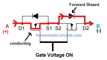
In this case we can see that when the gate voltage is applied, current from "A" is allowed to flow through left MOSFET, then through the internal forward biased diode D2 of the right side MOSFET, and finally the conduction completes at point "B".
When the voltage polarity is reversed from "B" to "A" the MOSFETs and their internal diodes flip their positions as shown in the following illustration:
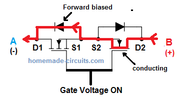
In the above situation, the right side MOSFET of the BPS switches ON along with D1 which is the internal body diode of the left side MOSFET, to enable the conduction from "B" to "A".

Making Discrete Bidirectional Switches
Now I have explained how a bidirectional switch can be built using discrete components for an intended two way switching application.
The following diagram shows the basic BPS implementation using P-channel MOSFETs:
Using P-Channel MOSFETS

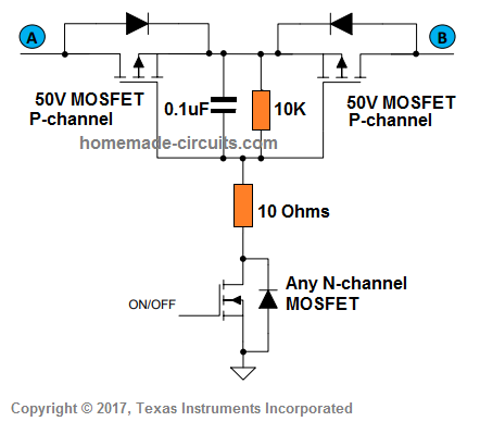
When point "A" is positive, the left side body diode gets forward biased and conducts, followed by the right side p-MOSFET, to complete the conduction at point "B".
When point "B" is positive, the opposite side respective components become active for the conduction.
The lower N-channel MOSFET is controls the ON/OFF states of the BPS device through appropriate ON/OFF gate commands.
The resistor and the capacitor protect the BPS devices from a possible in rush current surge.
However, using P-channel MOSFET is never the ideal way of implementing a BPS due to their high RDSon. Therefore these might require bigger and costlier devices to compensate against heat and other related inefficiencies, compared to N-channel based BPS design.
Using N-Channel MOSFETS
In the next design we see an ideal way of implementing a BPS circuit using N-channel MOSFETs.
In this discrete bidirectional switch circuit, back-to-back connected N-chanel MOSFETs are used. This method demands an external driver circuit for facilitating the two way power conduction from A to B and in reverse.
The Schottky diodes BA159 are used to multiplex the supplies from A and B to activate the charge pump circuit, so that the charge pump is able to generate the necessary amount turn ON voltage for the N-channel MOSFETs.

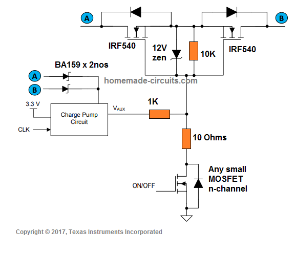
The charge pump could be built using a standard voltage doubler circuit or a small boost switching circuit.
The 3.3 V is applied for powering the charge pump optimally, while the Schottky diodes derive the gate voltage directly from the respective input (A/B) even if the input supply is as low as 6 V. This 6 V is then doubled by the charge ump for the MOSFET gates.
The lower N-channel MOSFET is for controlling the ON/OFF switching of the bidirectional switch as per desired specifications.
The only disadvantage of using an N-channel MOSFET compared to the previously discussed P-channel are these extra components that may consume extra space on the PCB. However, this disadvantage is outweighed by the low R(on) of the MOSFETs and highly efficient conduction, and low cost small sized MOSFETs.
That said, this design also does not provide any effective protection against over heating, and therefore oversized devices may be considered for high power applications.
Conclusion
A bidirectional switch can be quite easily built using a couple back to back connected MOSFETs. These switches can be implemented for many different applications which require a bidirectional switching of the load, such from AC source.
References:
TPS2595xx, 2.7 V to 18 V, 4-A, 34-mΩ eFuse With Fast Overvoltage Protection Data Sheet
TPS2595xx Design Calculation Tool