Within the next few years we may find all conventional capacitor-start type of ceiling fans getting replaced with BLDC ceiling fan circuits, since the concept allows the operation to be extremely efficient and save power by more than 50%.

Replacing Capacitor Start Fan with BLDC Fan
Just as the traditional incandescent lamps today are almost replaced with the much efficient LED lamps, it's now time for the ceiling fans to become smarter and more efficient.
In fact making a BLDC based ceiling fan circuit may be much easier than a capacitor-start type of fan, and could be done by even by an ordinary hobbyist having basic knowledge of electronics.
What you will Need
To achieve this, you may have to acquire or make the following modules:
1) A BLDC controller circuit.
2) An SMPS for powering the BLDC controller circuit
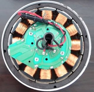
3) An appropriately matched BLDC motor.
4) propeller or blade fitting for the motor.
Main Specifications
The BLDC controller specs can be selected as per the available BLDC motor's specs, for example if you find it comfortable procuring a 220V or 310V BLDC you could probably go for a controller design having matching specs, such as the following circuit which was posted sometime back in this website.
Compact 3-Phase IGBT Driver IC STGIPN3H60
On the other hand if a lower rated BLDC motor in the range of 12V to 50V looks easier to obtain, one could think of selecting the following alternative design, which was also posted recently in this website:
50V 3-Phase BLDC Motor Driver Circuit

Since acquiring a 24V BLDC motor appears to be much easier than a 220V counterpart due to its easy availability in the market, we'll discus the proposed BLDC ceiling fan circuit using a 24V BLDC motor.
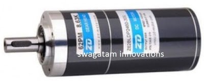
Let's assume we select a 24V 2 Amp BLDC for our ceiling fan, as shown in the following example, make sure it includes sensors with it:
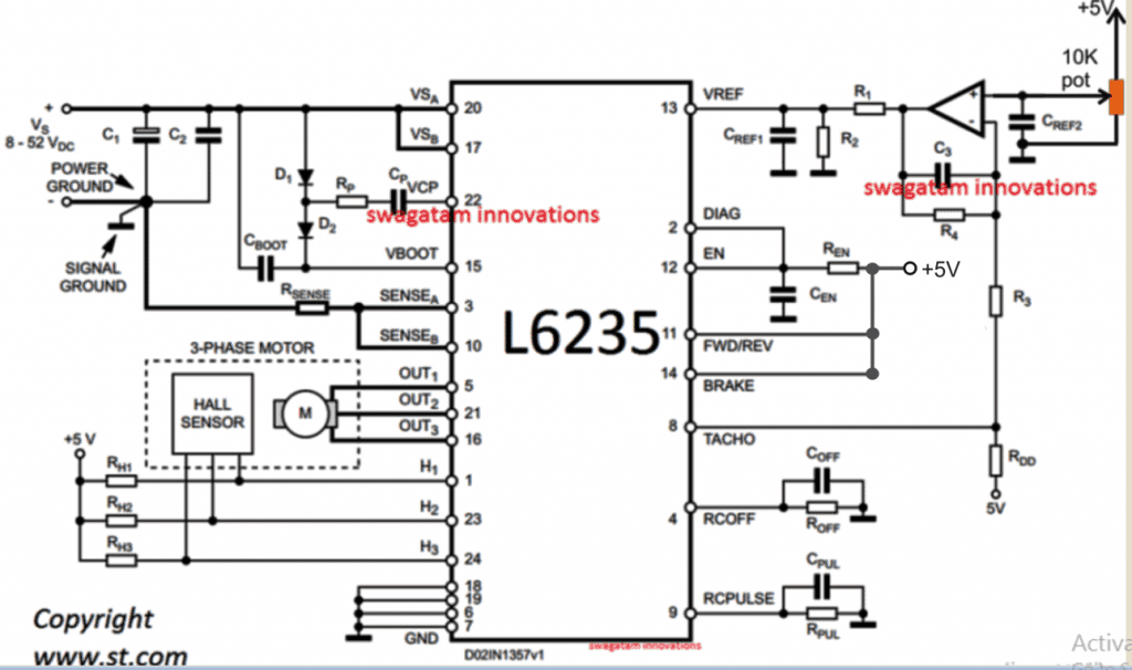
To control this motor and apply it like a ceiling fan, we can use the 50V driver circuit link as indicated in the previous paragraph, and modify the attached diagram to suit the ceiling fan control parameters, as indicated below:
Circuit Diagram

The diagram looks pretty straightforward, and you just need to connect the parts as displayed in the diagram, using a well designed PCB.
The 10K pot serves as the speed control knob for the ceiling fan.
Parts List
- C1 = 100 µF
- C2 = 100 nF
- C3 = 220 nF
- CBOOT = 220 nF
- COFF = 1 nF
- CPUL = 10 nF
- CREF1 = 33 nF
- CREF2 = 100 nF
- CEN = 5.6 nF
- CP = 10 nF
- D1 = 1N4148
- D2 = 1N4148
- Opamp = IC 741
- R1 = 5.6 K
- R2 = 1.8 K
- R3 = 4.7 K
- R4 = 1 M
- RDD = 1 K
- REN = 100 K
- RP = 100
- RSENSE = 0.3
- ROFF = 33 K
- RPUL = 47 K
- RH1, RH2, RH3 = 10 K
Power Supply:
From the above shown BLDC ceiling fan controller circuit, we can understand that the circuit will require a DC power for operating, and this may be fulfilled through any standard SMPS unit.
The best example is your laptop charger which can be effectively used for operating the proposed 24V BLDC motor, through the given controller circuit.
In case you decide building the SMPS yourself, you could perhaps try the concept explained in this 12V, 2 amp SMPS circuit.
Here the secondary winding ratio could be suitably doubled for getting the required 24V instead of the specified 12V in the design.
For the 5V supply you can use a 7805 IC based stage, and achieve the 5V requirement for the BLDC controller card.
Conclusion
The main objective of using a BLDC fan is to implement a capacitor less motor (or brushless motor) where the rotor does not carry any winding, which in turn ensures virtually zero friction and therefore extremely high efficiency compared to the normal capacitor type ceiling fan units.
You can use any BLDC for that matter, and power the DC circuit and the motor with an SMPS.
However it must be noted that motors rated with higher voltage will give higher efficiency for this particular application.
This concludes the explanation regarding the making of a simple BLDC ceiling fan circuit, if you have any related doubts let me know through your valuable comments.
