This circuit will allow the user to lock his car ignition using his phone Bluetooth, meaning the ignition can be locked/unlocked only through a specific code from the user's cellphone Bluetooth.
Overview
In one of my earlier posts I have already explained how to hack a Bluetooth headset and use it for any desired switching application via Bluetooth, here we apply the same concept for the proposed car ignition lock circuit using Bluetooth.In the project the cellphone becomes the Transmitter circuit, and the Bluetooth headset is used as the receiver.
If you do not wish to modify the Bluetooth headset into a receiver circuit, you an procure a readymade Bluetooth receiver unit also for the same
The idea is actually very simple, and may be understood by referring to the below given circuit:
How it Works
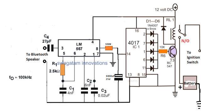
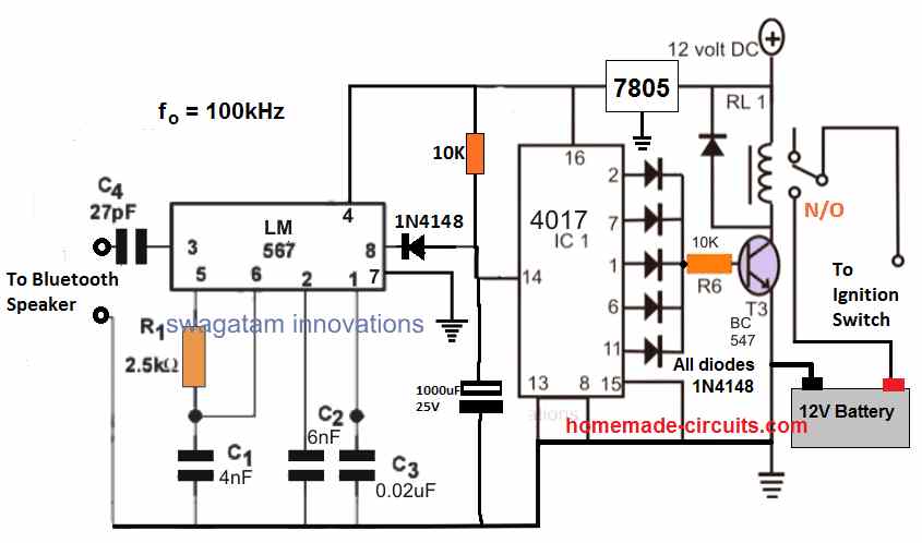
As can be seen the circuit is configured around a specialized phase-locked-loop IC LM567 which is designed to generate a low logic whenever it detects a frequency at its pin#3 that may be matching exactly to the IC's internal oscillator frequency set by R1/C1.
For example, in the above diagram the internal oscillator frequency is set at 100kHz by appropriately selecting the values of the R1/C1 timing components, therefore it implies that the IC will produce a low logic whenever it detects a 100kHz across its pin#3 and ground. As long as this situation is not satisfied, pin#8 can be expected to be at a logic high level.
The C4 end and the negative wire of the circuit is supposed to be joined with the Bluetooth headset or any selected similar Bluetooth audio receiver gadget. This could be also easily done through an opto coupler for allowing a complete isolation between the two stages.
This takes care of the Bluetooth receiver stage circuit, now lets' move on and learn how your cellphone needs to be set up as the Bluetooth transmitter unit.
For this, you will need to download a frequency signal generator app in your android phone, or if your phone is not an android phone, you can record a 5 second clip of the selected frequency, let's say a 100kHz frequency clip for the above shown design.
How to Test the Circuit
Once this is done, it's time to test the proposed Bluetooth car ignition lock circuit, through the following steps:
1) Pair up the phone and the Bluetooth receiver gadget with Bluetooth.
2) Toggle the 100kHz frequency from your phone and simply send it to thee receiver gadget.
3) Wait for a few seconds, and ...."click".... you will find the relay operating, and unlocking or locking the car ignition, depending upon the initial situation of the relay.
The slight delay in operating the flip flop relay is initiated by the 100k/1000uF components at pin#14, and this is crucial in order to make the system foolproof, so that an intruder may not make an attempt to break the lock by randomly sending a Bluetooth frequency to the receiver gadget.
This delay must be confirmed with some trial and error, the indicated values of 100k and 1000uF is arbitrarily chosen, and may not be accurate.
The IC 4017 is rigged as a flip flop circuit which toggles the relay ON/OFF alternately in response to the LM567 signal.
The relay can be seen integrated in series with the ignition switch which implies that as long as this relay is switched OFF, the ignition key cannot be used for starting the vehicle, and it would work only once the relay is triggered.
If you have any further queries regarding this circuit you can ask them through your comments below