
In this post I have explained a super capacitor charger circuit for charging super capacitors which converts a 12V car battery voltage to an elevated 16V for charging a bank of super capacitors. The idea was requested by Miariver.
Super Capacitor for Peak Power Compensation
First thanks for keep publishing this blog is very helpful, I have a question and I don't know if this is the right section!!! sorry for any inconvenient.
I am working from my car, running: a laser copier/printer, a die sublimation photo printer, a note book, 2 cellphones, and plus plus.
My inverter is (1500w 12dc-Battery in to 120ac out) a very good one.
after 4 hours of working the battery is getting too low, so the inverter starting to run on protection mode and beeping like crazy. So I decided to run a 6-pack of super capacitor in parallel with the battery to support the (peak moments) the problem is the super capacitor bank need to be charged to 16.2dc volts (6 times 2.7 volts each capacitor)
So do you have any idea how to get 16.2 volts from the 12 volts battery in order to keep the capacitors charged in order to hold the peak load when would be needed.
any idea, advise or circuit, would be highly appreciated.
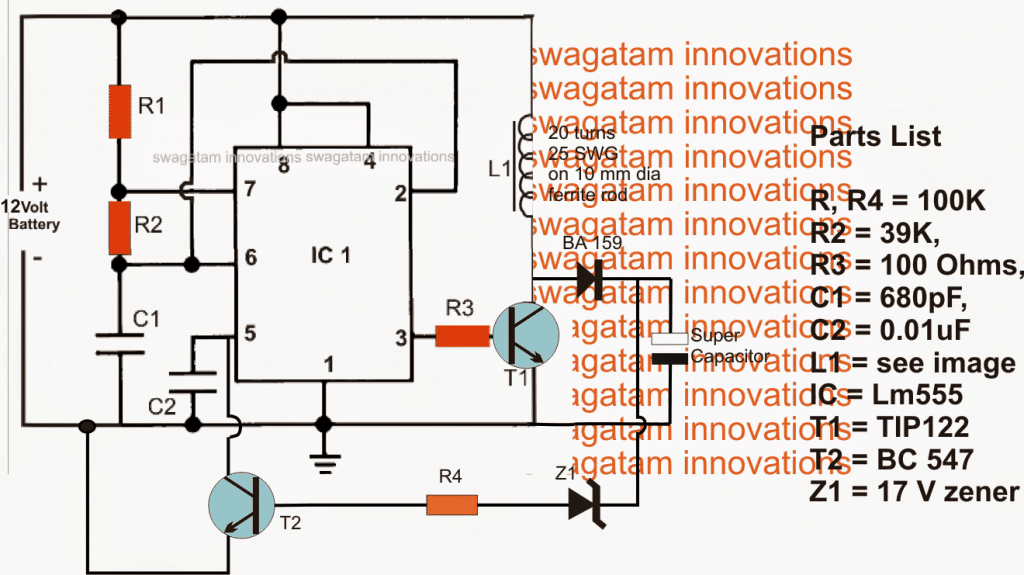
The Design
The proposed super capacitor charger circuit for charging super capacitor banks may be witnessed in the above figure.
The entire circuit can be seen wired around the ubiquitous IC 555, configured as a high frequency astable.
High frequency is required in order to drive a compact ferrite coil which becomes responsible for producing the required boosted voltage.
The relatively low current output from the IC is amplified using T1 which switches the connected ferrite inductor at the rate of the fed astable frequency.
The above action induces a calculated boosted voltage across the coil which is appropriately rectified using the attached BA159 fast recovery diode.
The resultant voltage at the cathode of the diode is fed to the associated super capacitors for the intended charging of the devices.
A feedback loop can be seen from the output to the base of T2 which ensures a perfectly stabilized voltage for the super capacitors....in case the voltage tends to rise above the predetermined fixed value, Z1 gets forward biased and switches ON T2 which in turn grounds pin5 of the IC choking the pulse width of the pin3 frequency.
This procedure quickly reduces the output to the safe limits and the cycle keeps switching ensuring that the voltage always stays within the set thresholds.
PWM Control
In the above design, R2 can be replaced with a 100k pot for achieving a PWM output across the load, although it may be not applicable for charging super capacitors, rather for some different relevant application .
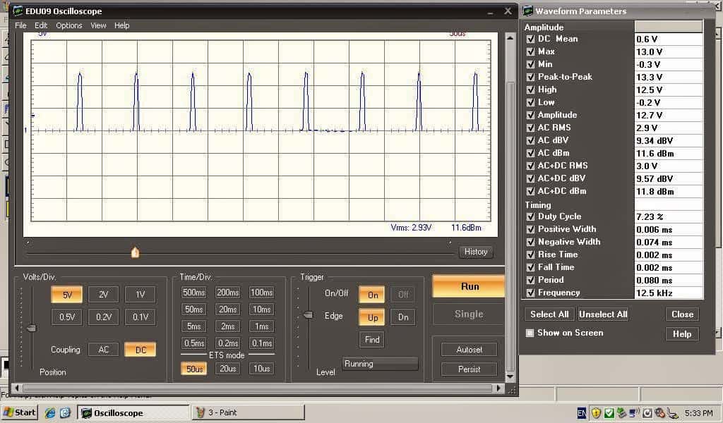
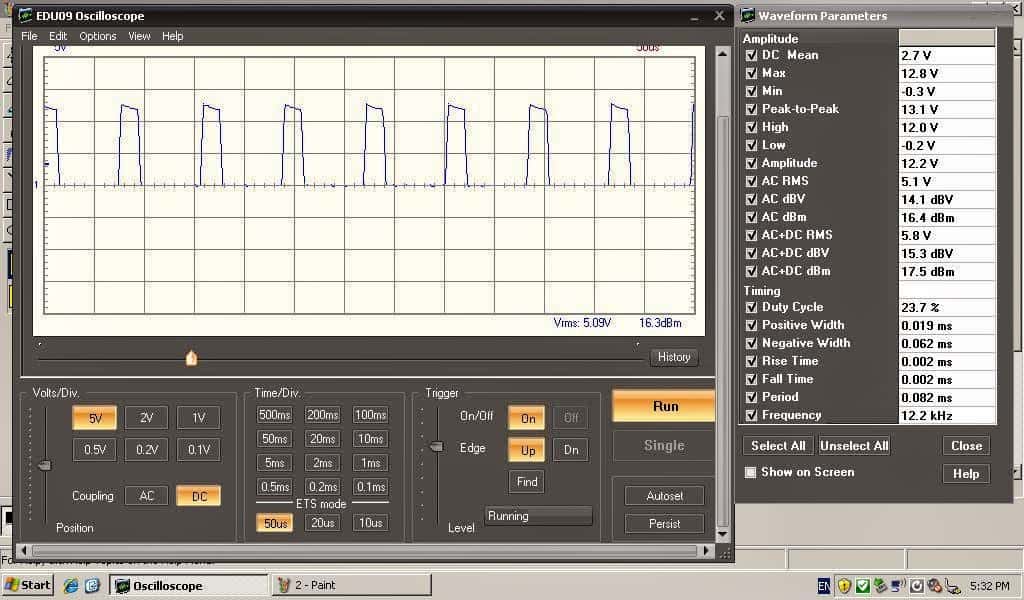
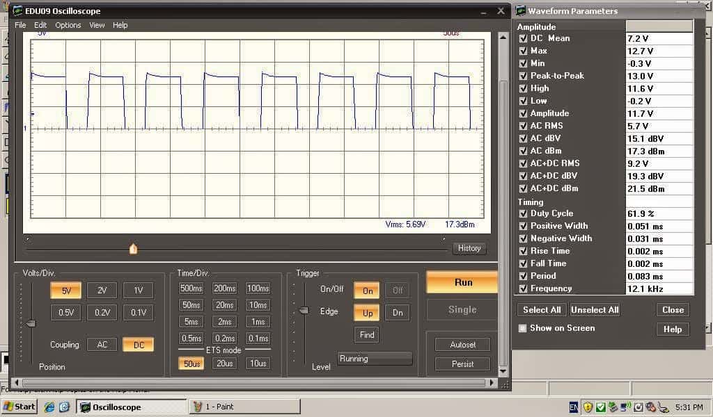
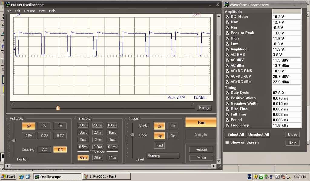
The above super capacitor charger circuit was tested and implemented by Miss Claudia who is an avid follower of this blog and a vehement electronic hobbyist, the verified results for the same may be witnessed with the following images, tested by Miss Claudia:
Another Useful Boost Converter Circuit for Charging Super Capacitor Banks from a 12 V Car Battery
Here's a voltage booster circuit which can be used for charging a super capacitor banks from a car lead acid battery.
The boost circuit has an oscillator stage using a BC548 transistor astable.
This transistor astable oscillator generates a high frequency output which drives a MOSFET based boost converter stage.
The circuit also has a feedback circuit stage using the 24 V zener diode which controls the output voltage level by switching the gate of the MOSFET appropriately.
This zener value can be adjusted for getting a customized boosted output voltage for the super capacitors
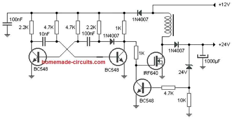
The inductor can be built by winding 30 turns of 1 mm super enameled copper wire over a 1 cm thick ferrite rod or a ferrite ring.