The open baffle hi-fi, high quality speaker design introduced here provides a substitute to the common loudspeaker housing. Its sound emission pattern resembles electrostatic pattern. It works without enclosure or housing for the woofers, although employs normal dynamics for the drive units. The reproduction provides extremely ‘spacious’ impact on the ears. Contributed by: Monty Trivedi
Design Considerations
Electrical energy is normally changed into acoustic energy through a dynamic drive unit. You can find other forms, like the electrostatic and ribbon units, however these are usually costlier and sometimes additionally more susceptible, or more complicated to build compared to classic cone type which has existed for around 70 years.
All around the world, many millions of loudspeaker drive units are manufactured yearly. Just a little percentage of these are created for hi-fi equipment: the rest is for use in telephones, car radios. portable radios, and so on.
Typically, the cone loudspeaker is only considered suitable for high-quality audio processing, since this type have the capacity to set a substantial level of air into motion (that is the sole important aspect to the physical hearing characteristic).
When a "diaphragm" has to replicate low frequencies, it is crucial that the front and rear of its cone are not able to ‘detect’ one another (or else, an acoustic short-circuit might happen).
Because of this, a sealed box or bass reflex housing is generally employed for the reproduction of low frequencies.
This kind of enclosure comes with the drawback, since it tends to oscillate with the cone (unless it's bolted on concrete).
A few specialists believe that the pattern should focus like a point source, that is, all frequencies ranges needs to be transmitted around an angle of 360°.
Practically, the radiation pattern of mid-frequency and tweeter units is restricted at around 180° ; only the woofers may reach around 360°.
You may find solutions to this, for example, fixing the drive units on the hind side of the housing also. Another option is the application of electrostatic drivers, because these push the waves forward and backward.
As the reproduced sound at the front side is in anti-phase with that at the rear, these models respond differently from an multi-directional radiator.
This kind of units are as a result known as dipole radiators, even though the radiation style is octagonal. The sound output from this type of unit can, however, be extremely pleasing to hear, simply because the sound waves from the backside arrive at the listener through several reflections, which enhance the stereoscopic impact.
The discussed open baffle high quality speaker box design, which, while not completely new in the music world, has hardly ever been the topic of a DO-IT-YOURSELF venture, aspires to blend these several factors. Put simply, one which executes as a dipole radiator but employs regular dynamic drive units.
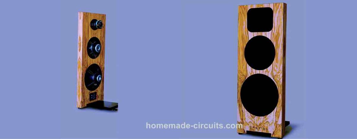
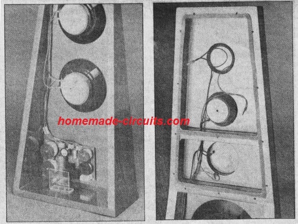
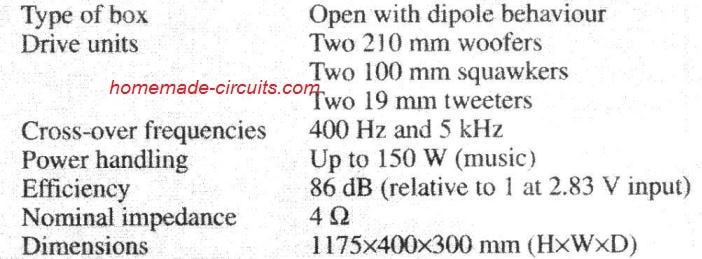
Low frequencies are processed by two woofers placed on a tiny baffle, while mid-range and high frequencies are processed by a couple of squawkers and a pair of tweeters, one of each at the front and one of each at the hind side.
Technical Hints
When a loudspeaker drive unit is fitted on the middle of a board, its frequency characteristic under the lower cut-off frequency (determined by the dimensions of the board) will decrease at the rate of 6 dB per octave.
Under the resonance frequency of the drive unit which will improve to 18 dB per octave, however this really is inconsequential when it comes to drive units having a low resonance frequency.
This effect is more preferable compared to that of a sealed box (12 dB per octave) or that of a bass reflex box (12-18 dB per octave).
Drawback obviously is, that the lower cut-off frequency is higher (half wavelength: diameter of board). With this frequency, front side and backside of the cone start to cancel each other in order that the resulting functionality degrades.
It is as though the air pressed forward in front is assimilated by the air drawn in by the cone on the backside. A cut-off frequency of 60 Hz needs a board of around 3x3 in (10x10 ft).
In addition, a clean characteristic demands the drive unit to be fitted asymmetrically, to ensure that the ‘short circuits’ are distributed spanning a broad frequency range.
This type of substantial board is, obviously, beyond the view for home-based application, where the models for identical functionality that occupy a reduced amount space.
Nonetheless, the open baffle design continues to be of curiosity, since it precludes the countless (undesirable) consequences an housing has on the reproduction of sound (standing waves: vibrating together, and so forth].
Vibration of the housing actually becomes a big challenge when the enclosure is constructed of wood. For household usage, a panel of moderate measurements put on the flooring of a room could possibly be tried to improve its dimension artificially and so reduce the cut-off frequency.
Furthermore electrical compensation may be applied to (to some extent) make up the acoustic decadence. This will likely lower the efficiency and power handling to some degree however this could be maintained within realistic boundaries through the use of a sizable cone and constraining the correction.
The current layout runs on the high, narrow board where a couple of 210 mm woofers are installed and is meant for vertical positioning on the ground. The (calculated) low cut-off frequency (-3 dB] sits at close to 100 Hz.
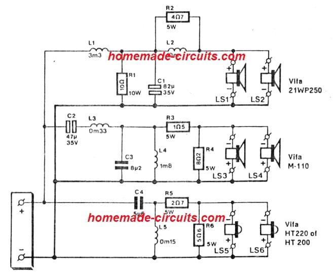
Because an additional amplifier was considered needless. the correction network is actually a passive LC type hooked up at the input of the woofers see Fig. 3.
Furthermore electrical compensation may be applied to (to some extent) make up the acoustic decadence. This will likely lower the efficiency and power handling to some degree however this could be maintained within realistic boundaries through the use of a sizable cone and constraining the correction.
The current Hi-Fi loudspeaker layout runs on the high, narrow board where a couple of 210 mm woofers are installed and is meant for vertical positioning on the ground. The (calculated) low cut-off frequency (-3 dB] sits at close to 100 Hz. Because an additional amplifier was considered needless, the crossover correction network is actually a passive LC type hooked up at the input of the woofers see Fig. 3.
Parts List
The (measured) characteristic of the woofer installed on a board that of the correction network and that of the adjusted loudspeaker are displayed in Fig. 1.
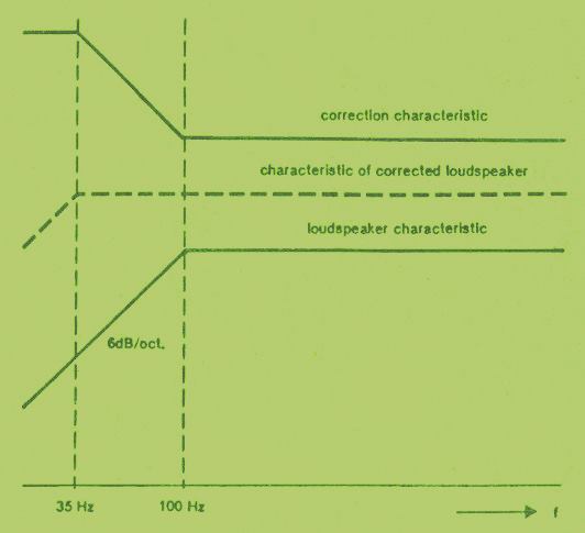
To maintain the efficiency and power handling within tolerable limits the correction has been constrained to just above 1 octave.
The efficiency is decreased by 8 dB. The use of a pair of woofers does not actually improve the efficiency (the overall impedance is lower although the dissipation is larger). and the power output continues to be practically identical as that of one 210 mm woofer in closed box. The tested characteristic are presented in Fig. 2.
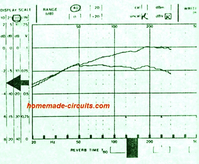
It is observed that the -3 dB cut-off frequency is reduced to about 35 Hz which is a good value for hi-Fi applications.
Note that the corrected curve consists of the effects of the low pass filter in order that it begins to slide of yet again over 200 Hz. The resulting dc symbol is a narrow baffle that offers better bass output at lower Hz than several ‘traditional' speaker boxes.
It may seem as though the proposed open baffle layout will not reproduce the low frequencies nicely. However that may be due to the fact that box designers usually do not enable for the effect of the real room or space, resulting in a low frequency peak as soon as the loudspeaker is utilized for the room.
The characteristics of the woofers tested in front and back are essentially the same at low frequencies. This is simply not the situation with squawkers (mid-range units and tweeters, which implies that these need to be replicated at the rear end.
Moreover squakers have greatly curved frequency characteristics and inferior radiation efficiency. For that reason it became important to put those units in a small housing
Selecting the Drive Units
To witness an improved radiation the diameter of the drive units are required to be small compared to the reproduced audio wavelength.
Therefore a three-way method is necessary. Given that the selecting various types of drive unit in a system usually gives rise to availability difficulties, it was opted to pick out all 3 types in the range of a single supplier.
The Cross-Over Network
The circuit of the cross-over network can be witnessed in Fig. 3; its tested output in shown in Fig. 4. Inductor L2 and R2 provide the low-frequency correction as indicated in Fig. 1.
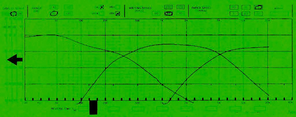
Filtering proper is done by L1-C1. This section gives a second-order slope approximately above 400 Hz (it looks to be fairly reduced Fig. 4, but that may be since the curves there relate to the electrical output only: the efficiencies of the drive units are not included.
Resistor R1 guarantees a fairly steady resistance at the output of the system, regardless of the impact of L2-R2 and the frequency-dependent impedance of the woofers. The portion for the squawkers comprises of L4-C2 for the roll-off at 400 Hz and L5-C3 for the same at 5 kHz. The slopes are approximately 12 dB per octave.
Along with the natural roll-off of the tweeters, this produces a sharper slope, which is crucial to make sure that the mid-range devices do not deal with an excessive amount of power. Attenuator R3-R4 between the section and the drive units offers level matching at near 3.5 dB. The tweeter section (second-order) includes L5-C4.
Attenuator R5-R6 provides level matching approximately at 5.5 dB to offer an ultimate, flat acoustic frequency response. The cross-over network is best developed over a small general purpose veroboard see Fig. 5 for an appropriate component layout.
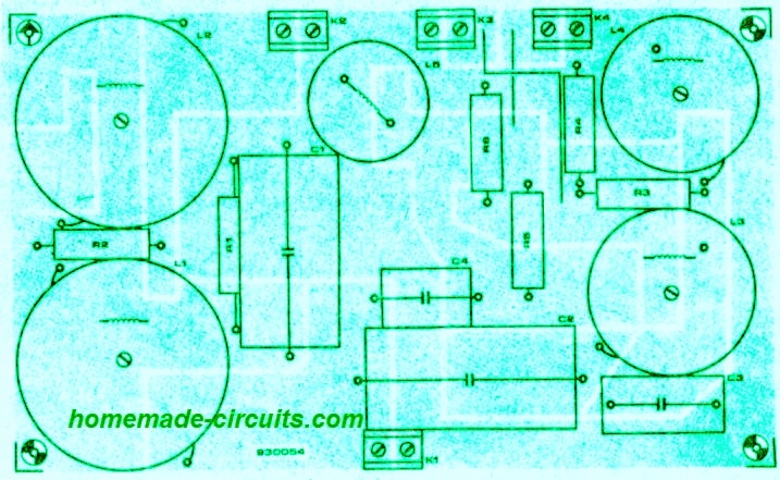
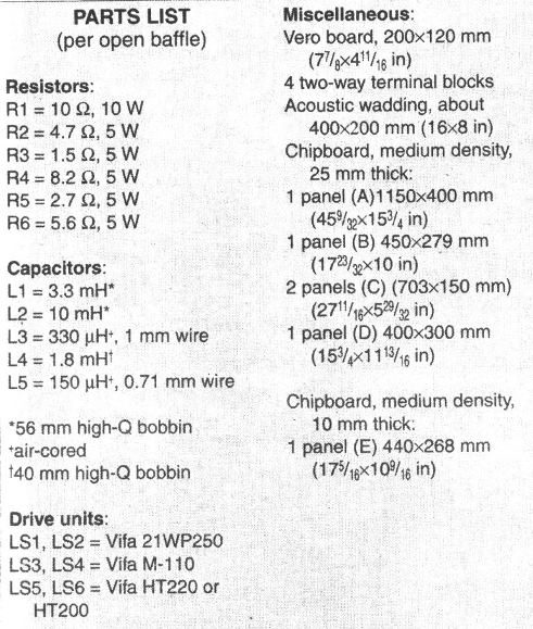
The cored inductors are pretty heavy and, therefore must be clamped properly, if possible with nonmetallic nuts, bolts and washers. Inductors L1, L2, and L4 are bobbin types with an HQ core. This material does not create distortion at both high and low frequencies and is also quite cheap.
Since L1 and L2 are supposed to carry relatively substantial currents are air core inductors or have a nonferrous or inferior core material. Despite the fact that C2 is chosen as a bipolar electrolytic, an MKT type can also be used as effectively.
How to Construct
Essentially all the sections displayed in Fig. 6 are manufactured from 25 mm [1 in] medium density chipboard. The major element is panel A, a 1150 mm high board on to which a pair of woofers, a squawker and a tweeter are fitted.
Observe that all drive units has to be bolted into sunk holes, which will substantially increase their radiation efficiency. This is, however, only essential at the front side, because the audio transmission from the back isn't that important.


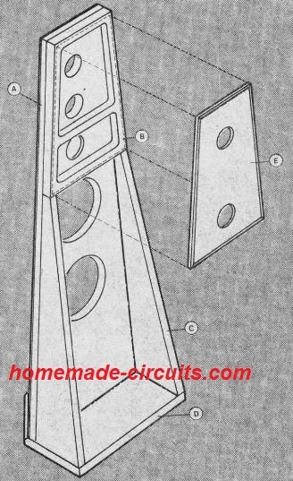
A sideview of the design thus far appears like an individual, 50 mm [2 in) solid section that broadens on the base.
Finish off this as necessary in lacquer or veneer. Remember the panel E Once the laquer or veneer dries up, work the cords for the loudspeakers and install the drive units at the front—don't overlook the cables for the back squawker and tweeter.
Hook up the cables to the devices. Tag the cable ends, in order that it doesn't create confusions afterwards regarding the various cable terminals.
The holes through which by which the wires go through should be sealed waterproof using, e. g. a glue gun. Subsequently, secure panel E with chipboard screws towards the top rear as indicated in Fig. 6b. The screw heads should be counter-sunk.
Cover up the spaces between the panels with appropriate taping. After that install the rear squawker and tweeter.
Ensure that the cable connections to these sections are replication of those in front; meaning, connect the + line of the front tweeter to the - line of the rear tweeter, and likewise with the mid-range units.
The electrical polarity in accordance with the cross-over network will depend on the front loudspeakers.
Next, install the cross-over system under the woofers as demonstrated in the photograph in Fig. 7. Lastly, create an L-shaped mount as presented in Fig. 7, bolt this to the base panel as indicated and fit the sockets to this. Hook up the sockets to the cross-over network as suitable.
Technical Specifications


I simplified the implementation even more, by using a new 12″ full range driver in an open baffle, actively crossed to 4 15″ woofers in W Frames. An old equalizer boosts the bass only array and stereo amplifier.
Sounds interesting!! thank you for the feedback
In my experience there were several home subwoofers. Finally I built an H-dipole subwoofer. Then an insight came.
Parallel filters for multiband speakers are not the best solution – only serial ones give the correct idea of medium-high frequency sound reproduction.
Thanks for sharing the info, appreciate i!
Pak apakah ada rangkaiaian hometheater5.1,yg bapak buat,lengkap dngan amplinya yang multikanal,beserta rangkaian catu dayanya,dgn mnggunakan 1 trafo aja
I don’t have a commercial 5.1, but you can easily make one using the following link:
https://www.homemade-circuits.com/exploring-ic-tda-7560-4-x-45w-quad/
this will be in the 4 corners of the room.
For the center you can use any high power amplifier and use the following low pass filter at the input for creating heavy bass:
https://www.homemade-circuits.com/make-this-low-pass-filter-circuit-for/