A subwoofer amplifier is basically a power amplifier designed to filter and extract the low frequency content from the input audio signal and amplify it to the desired levels.
This allows a sound reproduction that is enhanced with deeper bass, generating a concert hall like, or an immersive theater like sound effects.
By: Sania D'souza
You may find many individuals experimenting with home theater systems by attaching a TV or PC to a music system's auxiliary ports. For most situations, this straightforward setup is a substantial improvement over the TV's built-in speakers.
Popular small table-top style audio systems, on the other hand, rarely feature speakers large enough to deliver the deep bass that offers theater sound its volume and strength. The subwoofer speaker on the other hand is responsible for this key aspect of home-theater sound.
There are two types of subwoofers: passive and powered subwoofers. A passive crossover network and a speaker installed inside a loudspeaker box are the most common components of passive subwoofers.
While this type of subwoofer is the cheapest, it requires an external amplifier to drive it, and most integrated audio systems amplifiers are too tiny to efficiently operate a passive subwoofer.
The proposed mini ground-shaker is an active crossover powered subwoofer with a 50-watt power amplifier, a 10-inch driver, and a fourth-order bandpass enclosure.
The built-in power amplifier of the subwoofer circuit allows it to function with almost all types of sound systems.
Circuit Description
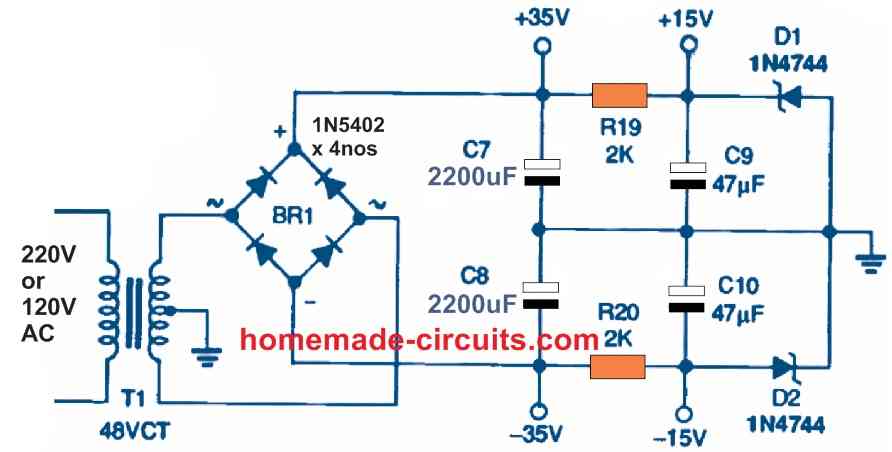
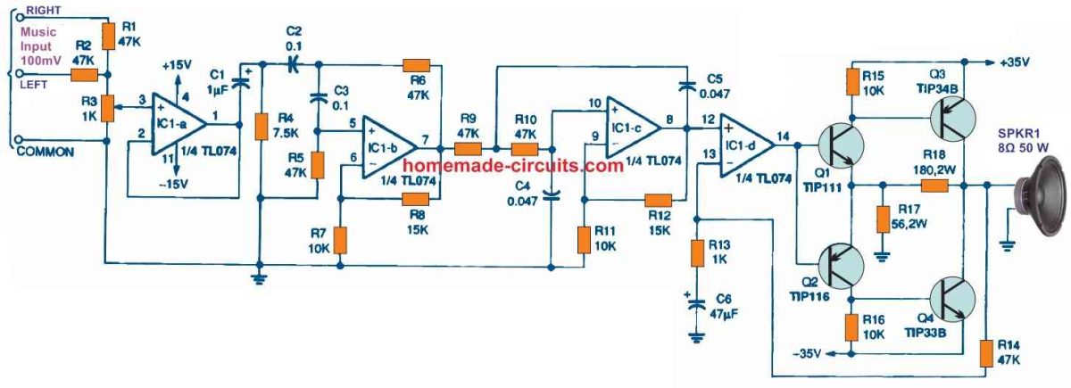
The circuit diagrams of the powered subwoofer are shown in Figures below.


A center-tapped 48-volt transformer, bridge rectifier, and filter capacitors C7 and C8 make up the power supply.
The output voltage after being rectified and filtered is around 35 volts. Zener diodes D1 and D2 and resistors R19 and R20 regulate the power supply outputs for the op-amp IC1 to 15 volts.
The TL074 quad op amp (IC1) works like an input buffer, bandpass filter, and an output driver for the entire circuit.
Resistors R1 and R2, potentiometer R3, and unity-gain buffer IC1a constitute a mixer and voltage divider stage at the input circuit.
R3 is a potentiometer that may be used to control the subwoofer's output to the appropriate level.

Using capacitors C2 and C3, and resistors R5 and R6, opamp IC1b creates a 12 dB per octave high-pass filter.
With the numbers provided, the cutoff frequency for this filter is 1/2πRC, or around 34 Hz. The gain and Q of the filter are controlled by resistors R8 and R7.
At roughly 20 Hz, capacitor C1 and resistor R4 provide an extra 6 dB per octave high-pass filter. IC1c, C4 and C5, and R9 and R10 together form a 12 dB per octave low-pass filter.
The low-pass cutoff is set at 72 Hz using the parameters provided. R11 and R12 control the gain and Q of this stage.
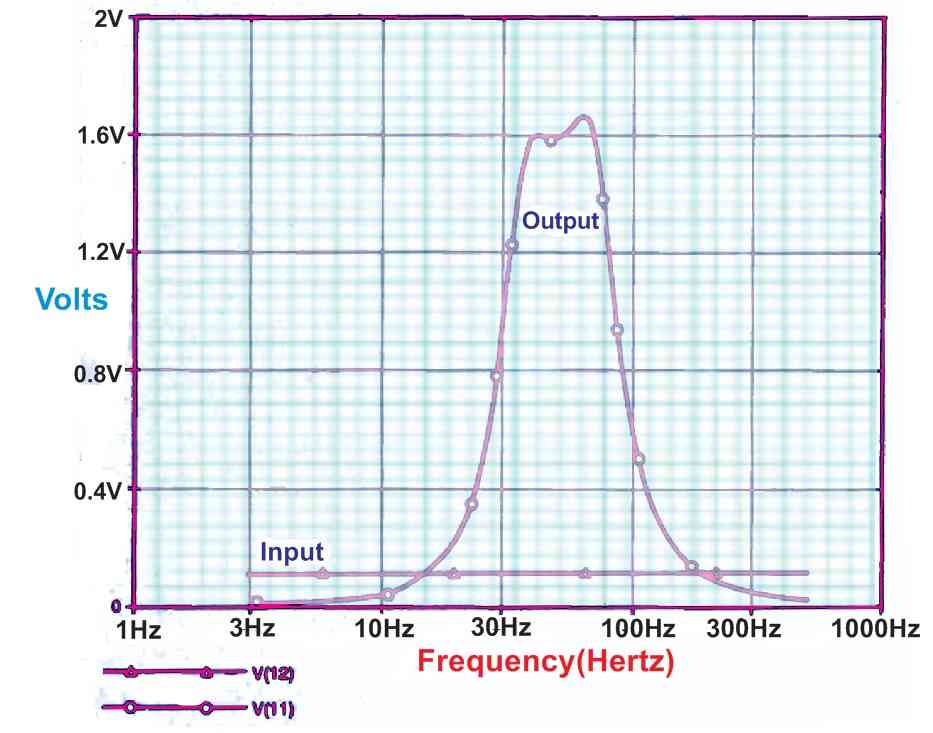
Connecting these two filters one after another creates a bandpass filter with the frequency response as depicted in graph below.

For increased efficiency, the output stage works like a class-B amplifier. Crossover distortion, which is prevalent with class B amplifiers, is practically reduced with the TL074's fast slew rate. The amplifier's distortion specification tends to be at a frequency range which the subwoofer speaker is unable to reproduce.
The output of op amp IC1d may swing around 10 volts peak while working with 15 volt supply in order to drive the transistors Q1 and Q2.
Negative feedback is provided by resistors R17 and R18, which adjust the output stage's gain to around three. As a result, the output can reach to an optimum peak voltage of roughly 30 volts.
The max power output into an 8-ohm load is (30 x 30/8)/2 = 56 watts RMS if the transistors are rated with high-gain specifications as indicated.
Resistor R13 and feedback resistor R14 determine the amplifier's total gain. DC isolation is delivered via capacitor C6.
Box Layout
A subwoofer's box is a crucial part of its configuration. A fourth-order bandpass cabinet was created with the use of computer software for this mini ground-shaker.
The digital model is determined by the characteristics as shown in the following graph, provided for a 10-inch speaker. The speaker cone's peak movement was chosen to be 1 inch.

A loudspeaker having matching characteristics must be chosen for optimum performance.
The amplifier and loudspeaker must be housed in a sealed chamber with dimensions of 18 x 15 x 8.5 inches and a capacity of 1.2 cubic feet.
The loudspeaker box is oriented such that the speaker cone is facing the floor. Supports on either side of the cabinet keep it 1.5 inch above the floor, resulting in a front compartment with a capacity of 0.2 cubic feet.
The support open ends serve as two ports, both spanning 1.5 x 12.5 inches.
How to Test
The first thing is to make sure that the power supply is operational.
Check that the emitters of Q3 and Q4 are receiving +/-35 volts DC, and that IC1 is receiving 15 volts DC on pins 4 and 11, appropriately. Test the DC voltage at the output as well (across the Q3/Q4 collectors).
If the output voltage is higher than 0.1 volt, check that the parts, particularly C6, are properly placed.
A loudspeaker could be damaged if the voltage at the amplifier's output is very high.
In case you have an access to a function generator and an oscilloscope, you can hookup the function generator to the input ports, and the oscilloscope to pin 8 of IC1 to test the bandpass filter's functionality.
Execute a frequency sweep test from 20 to 150 Hz or more using a sinewave input signal of a few volts, and confirm that the oscilloscope output voltage maintains the pattern depicted in the graph above.
Practical Implementation
Install the finished sub-woofer circuit in a location where the input cables and power cable could be kept hidden in the listening room.
It's critical that the subwoofer is connected correctly to the music source or the stereo amplifier.
Connect an ohmmeter across the negative terminals of your stereo amplifier, making sure that the power supply is switched off and the speakers detached.
Connect just one input in case the input ends are not short circuited with one another or if your stereo amplifier is in mono-bridged mode.
Keep the subwoofer's negative terminals shorted together with the ground line. Hookup the subwoofer's negative connections to the negative line of your stereo amplifier.
If the positive output terminals of your stereo amplifier are short-circuited together, it would almost probably be destroyed.
Set the volume knob all the downward and hookup the subwoofer power cord into an AC mains outlet after the input connections are correctly joined.
Setup the volume of your stereo system first, and then adjust the subwoofer pot.
Tweak the bass control on your stereo system to finely adjust the subwoofer level, only if your stereo also has its own tone controls adjustments.
You may explore the world of music and intrigue hidden deep within the music frequency range with the mini shockwave subwoofer circuit.
You can go on listening to all of those amazing movies once again, and experience a real theater like sound of the deep bass from this subwoofer circuit for the first time in your own home!
Another Deep Bass Subwoofer Filter Circuit
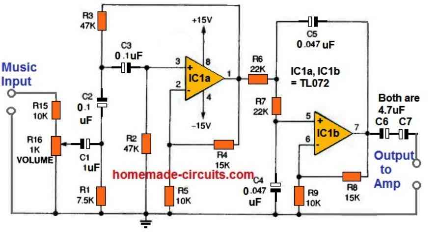
Here's another design which can be used for building a deep bass subwoofer unit.

A schematic representation of the high bass Subwoofer circuit is shown in the above figure. The circuit's brain is an IC1a TL072 twin JFET op-amp.
Op-amp With capacitors C2 and C3 and resistors R2 and R3, IC1a creates a high pass filter. IC1b, along with C4, C5, R6, and R7, creates a low-pass filter.
The following formula is used to determine this form of filter's cutoff frequency:
f = 1 /(2πRC)
The high-pass filter cuts off at around 34 Hz, while the low-pass filter cuts off at approximately 150 Hz, using the values provided.
Resistors R4 and R5 control the high-pass filter's gain, while R8 and R9 control the low-pass filter's gain.
The voltage divider formed by resistor R15 and potentiometer R16 may be adjusted to control the subwoofer volume.
When the system is first installed, this adjustment is recommended to calibrate it.

Have Questions? Please Leave a Comment. I have answered over 50,000. Kindly ensure the comments are related to the above topic.
Hi sir
Can we change the op amp circuit to inverting from non inverting. and non inverting to inverting.
Hi Imran,
Sorry that may not be possible and is not advisable.
Hello,
I am having hard time getting TIP33B/34B. im not sure about impact on sound quality of these parts, so could you please recommend replacement?
Hi, those transistors are NPN/PNP complementary pairs with 10 amp handling capacity. I am not able to find any proper replacement for these complementary pairs….maybe the part dealer might be able to help you.
If you don’t find any replacement, you can try TIP3055/TIP2955 instead.
cct.diagram and description is
exellent.I am following it and going
to assemble soon.thanks for sharing valuble knowledge.
Thank you, and glad you liked it!
Hi price of electrons mr Swagatam , am still alive this is your former student kaluya moses from uganda.
happy new year sir.
Mr Swag, i would like to help, If you can design for me clean sound woofer/sub- woofer circuit of 100 watts/ 150 watts
Hi Kaluya, Glad to see you back after so many years. Happy New Year to you too.
I think you should try the subwoofer idea which is published in the above article. It is specifically designed to create an extreme bass output. The power output is 50 watts, but can be easily upgraded by replacing the output transistors with the following types:
https://www.onsemi.com/pdf/datasheet/2n5684-d.pdf
Thank very much for quick response as usual , prince of electronic Swagatam. I will update you God bless you.
It’s my pleasure Kaluya, all the best to you!
Do anyone have Circuit where Using RFID technology Locating a object in a stock of parcels in parcel office. Like in parcel office operator will enter the RFID tag in his computer a Laser light hanging in the middle automatically focus light on the parcel to locate that parcel which is in the pile of stocks.
good after noon sir,Im looking for a circuit that can read, the volts on a 1n4000 to 1n4007 diode, to see if they are still working thk
Hello Ulises, sorry, I do not have this circuit at this moment, I will try to get it.
Hi sir, thank you for this projects, kindly help me the diagram that can filter sound from main bass to tweeter. Or bass and tweeter from the same circuit using tda7379.
Hi Shila, sorry I have no idea how to extract only voice frequency using IC TDA7379.
However you may refer to the following article to learn some filter circuits:
10 Useful Active Filter Circuits Explored