In this post I have explained a buzzer circuit with an incrementing beeping rate, which can be used in critical warning signalling applications. The idea was requested by Mr. Lee.
Buzzer with Progressive Beep Rate
- Could you help me with a circuit. I've been trying to find but so far had no luck! I need a pulsing piezo that will start with a short blip and then over a period of may be 2 minutes, progressively increase the frequency of blips to maybe then permanently on or just rapid blips, similar to a game type of timer where the blips get quicker as the seconds pass.
- I want to use it on a car(so 12volt) to indicate when an anti car jack type immobilizer is about to operate. I've got ideas for the main immobilser circuitry but i'm struggling with the rising pulse rate buzzer/piezo.
- To simplify it slightly i would just use a 12v piezo driven by the rising pulse circuit.from when power is connected the timing cycle can start and maybe a variable resistor to tweak the pulsing cycle?
- Any ideas would really really be appreciated-if you can help,
The Design

The requested design for a buzzer circuit with progressive or an incrementing beep rate can be basically implemented through a voltage to frequency converter circuit
Although you may find many variants of voltage to frequency converter circuits, these may not be entirely easy to build due to their fairly complex design or due to the inclusion of unpopular, obsolete IC in it.
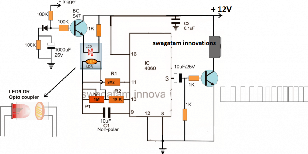
An alternative easier way of achieving this function could be by modifying an existing IC 4060 astable circuit with a homemade LED/LDR optocoupler as shown above.
As can be seen in the diagram, the LED/LDR opto is triggered through a slow rising voltage across its LED leads, which in turn induces a correspondingly slow decreasing resistance on the attached LDR.
The slow decreasing resistance of the LDR causes the timing capacitor of the astable to charge at proportionately faster rate, which subsequently causes a proportionately progressing or augmenting frequency rate at the output of the IC 4060.
P1 is for fine tuning the timing delay between the progressive beeps, possibly this component could be completely eliminated.
C1 can be also tweaked for adjusting the delay period between the beeps in order to make them faster or slower as per the application requirement.
The indicated buzzer unit here may be procured readymade in the form of a piezo buzzer or this can be also built at home by following this simple buzzer circuit guide.
Update:
Another interesting way of implementing a progressive buzzer beeper circuit could be by using a IC 555 monostable circuit and apply a slow rising voltage at its pin#5 control input....will update the circuit soon here.
