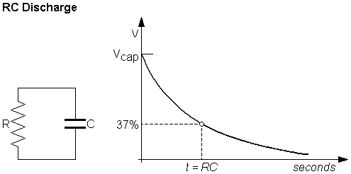
Capacitor charge and discharge periods is usually calculated through an RC constant called tau, expressed as the product of R and C, where C is the capacitance and R is the resistance parameter that may be in series or parallel with the capacitor C. It may be expressed as shown below:
τ = R C


The RC constant tau may be defined as the period required to charge a given capacitor through an associated series resistor by a difference of approximately 63.2% between its initial charge level and the final charge level.
Conversely, the above expressed RC constant may be defined as the period required to discharge the same capacitor through a parallel resistor until 36.8% of the charge level is left.
The reason behind setting these limits is the extremely sluggish response by the capacitor beyond these limits which causes the charging or discharging processes to almost take an infinite amount of time to reach the respective full charge or full discharge levels, and therefore is ignored in the formula.
The value of tau is derived from the mathematical constant e, or

and to be more precise this may be expressed as the voltage required for charging the capacitor with respect to the parameter "time", as indicated below:
Charging
V(t) = V0(1−e^−t/τ)
Discharging
V(t) = V0(e^−t/τ)
Cutoff frequency
The time constant
τ

τ = R C = 1/ 2 π f c
rearranging the above gives:, f c = 1 / 2 π R C = 1/ 2 π τ
where resistance in ohms and capacitance in farads yields the time constant in seconds or the frequency in Hz.
The above expressions may be further understood with short conditional equations, for example:
fc in Hz = 159155 / τ in µsτ in µs = 159155 / fc in Hz
Other similar useful equations are represented below which can be used for assessing a typical RC constant behavior:
rise time (20% to 80%)
t r ≈ 1.4 τ ≈ 0.22 / f c
rise time (10% to 90%)
t r ≈ 2.2 τ ≈ 0.35 / f c
In certain complicated circuits that may accompany in excess of one resistor and/or capacitor, the open-circuit time constant approach happens to offer a way of deriving the cutoff frequency by analyzing and calculating the total of many associated RC time constants.
Hi Mr Swagatam;
If the subject is smps circuit and input 220V AC output 72V Dc battery charger. We see high voltage about 320V and double high voltage capacitors at the primary side (each has about 160V). When there is no load we will apply input voltage for a while and then unplug it. In that case it is possible to say about the voltage and time value grapic untill they discarge in bold outline.
Hi Suat,
You can find the capacitor discharge graph online, you will be able to see that the charge exponentially keeps declining but never reaches zero.