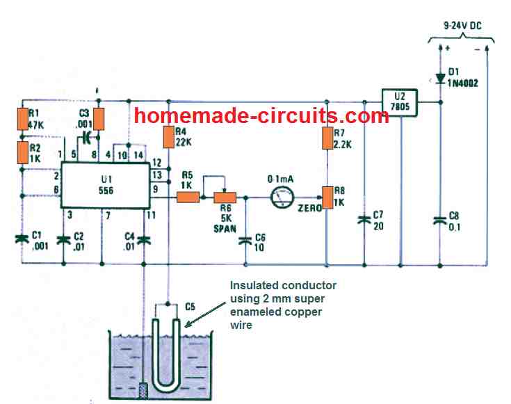
At times it becomes important to determine the amount of water inside a sealed tank, by employing a stationery sensor. A sensible remedy to the issue is to make use of a cylindrical capacitor concept. One plate of the capacitor is created with the liquid surrounding an insulated conductor, where insulation of the conductor works like the dielectric while the capacitor's second plate is formed by the wire itself.
The capacitive fluid meter presented in the following article allows the user to know or see the fluid level inside a sealed tank through a meter reading, using an insulated copper wire fixed inside the tank which acts like a capacitive sensor.
Basic Idea
The idea is actually simple but interesting. An insulated wire is dipped inside the tank fluid, the fluid is applied with a ground or negative potential, while the internal conductor of the insulated wire is connected with an external detector/amplifier circuit.
The conductor inside the insulation is unable to come in direct contact with the fluid, however, it is able to detect the fluid through capacitive effect, with respect to the ground connection of the fluid.
When the fluid level is high, the capacitive effect is higher around the insulated conductor, and vice versa. This capacitive influence is detected by the external circuit and an equivalent reading is translated over a moving coil meter.
The liquid level inside the sealed tank will be proportionate to the capacitance of this liquid/conductor electrode, which could be determined by a straightforward circuit for converting the linearly varying nature of this capacitor into a linearly varying voltage level, which may be proportionate to its capacitance.
How it Works
The center of the capacitive fluid meter circuit as shown in the diagram, is a monostable circuit configured with the help of the capacitive transducer inside the fluid and 1/2 of a 556 dual oscillator/timer.

The PWM output from the monostable is relative to the capacitance of the RC timing circuit consisting of R4 and the adjustable capacitance of the fluid/conductor capacitance C5, which is directly proportional to the total area of the conductor dipped inside the liquid.
The other 1/2 of the IC 556 timer is configured like a clock operating at 22 kHz that delivers the trigger pulses to the monostable. Depending on the level of the fluid inside the tank, the capacitance of the "C5" probe varies, which in turn causes the monostable timing to vary.
The varying monostable output from IC is fed to a moving coil ammeter which converts the varying pulses into a meter reading that directly proportional to the the fluid level inside the tank.
A graphite rod removed from your old lantern battery can also used as the ground probe in a situation when the tank is made up of a non-conductive material. Potentiometer R6, a 5K unit, can be used for calibration of the meter's range.
What would be the issues if this circuit was used in a black water holding tank?
Would the dried affluent effect the capacitance on the probe and/or the graphite ground probe?
Probes for measuring tanks with affluent have historically failed due to clogging, corrosion, and layers of impurities drying on the probes.
It should work, since the affluent would be full of minerals, which will help greater conduction and capacitive effect. The central sensor wire is supposed to be a super enameled insulated copper wire so corrosion can never happen in this concept.
An arc will not ignite a flammable fluid if it occurs in the liquid. If the arc occurs above the liquid surface, it still will not ignite. It is only when the vapors of the liquid combine with air at the proper ratio that combustion occurs.
Will this circuit work for Petrol? E.g, as a motorcycle fuel Gauge?
If the ground link is held close to the copper wire then perhaps it might work with petrol or gasoline tanks also…