In this post I have explained and tries to solve a common car door opening issue which may be seen in quite a few old model cars. The proposed circuit of a car door close optimizer was requested by Mr. Mark Rothwell.
Technical Specifications
Just stumbled across your site, hope you can help/advise me?I have a 1999 Mercedes SLK and it has a well-known design flaw, the doors are frameless and the windows have the closed position set mechanically by a small metal bracket glued to the window within the door which stops the window at the correct position when closed so when the doors are opened and closed the window just catches the rubber seal as the door closes and allows the window to slide into the recess.
The problem is these brackets fall off allowing the window to close a couple of mm higher than designed which isn’t a problem for the window mech but this causes the window to catch on the rubber door seal and not sit into the seal recess properly, the only way to close the door properly is to drop the window slightly before closing the door.
The door seals on my car are being worn out by the window rubbing on them when the door is closed and the on closing the window is being held on the outside of the door seal so I had an idea to incorporate a timer circuit to drop window few mm on opening the door then close it again after the door is shut, ideally to be activated by the ground signal for the interior lamp (i'm assuming its a ground sig but haven't checked yet)
BMW 3 series (and poss others) have for many years had such a system incorporated in the car at manufacture that drops the window a couple of mm when the door is opened and closes the window when the door is closed and I think this car should have had this system when designed!
My idea is to use a 555 timer circuit to achieve this but the last time I dabbled in circuit design was over 20 years ago and it is giving me a big headache trying to remember the theory, any help or advice would be much appreciated and although most modern cars have now taken BMW’s initiative and now include this function there may even be a market out there for such a seal saving device on older cars?
How the Circuit is Supposed to Work
1) Door opens, ground signal applied from door switch
2) Momentary energises relay or output to apply +12V 20A for approx 500 milliseconds (this time may need to be adjusted when fitted) to momentary send the window down (open) a fraction (this output to be connected to the window open button of the car)
3) On closing the door, ground signal removed
4) Momentary energises relay or output to apply +12V 20A for approx 1 second (this time may need to be adjusted when fitted) to momentary send the window up (closed) (this output to be connected to the window close button of the car)
Any advice much appreciated!
Mark
The Design:
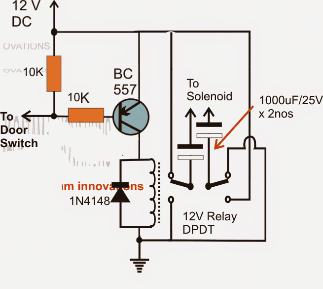
The presented car door close optimizer circuit is simple enough, and self explanatory. As soon as the car door is opened, the transistor receives the required negative base bias triggering the attached DPDT relay.
The DPDT relay contacts along with the 1000uf capacitors are wired such that the output across the capacitors changes polarity and switches ON the load only momentarily every time the door is opened or closed.
The change in polarity is required for enabling the capacitors charge and discharge process which in turn is necessary for the required transfer of the momentary pulses to the connected load.
The above design was suitably modified by Mr. Mark, I have explained more about it:
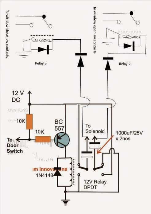
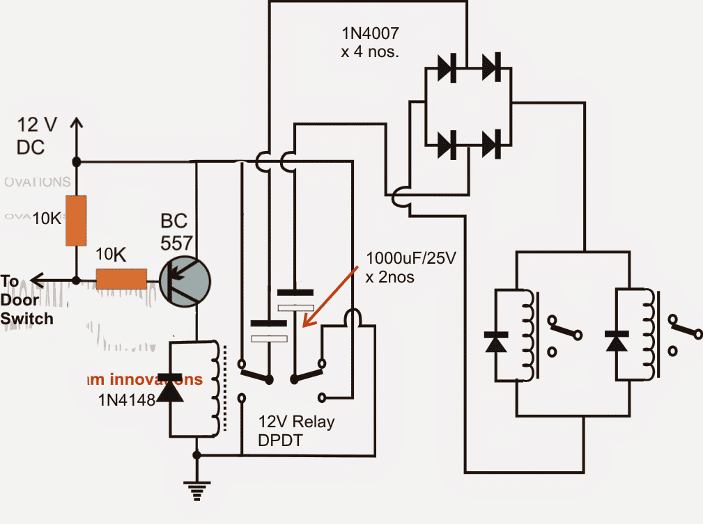
I was intending to connect the circuit to the contacts of the window switches, ive attached a jpg with some additional components, I think this will work with the additional relays using the solenoid outputs to drive 2 relays when each of the outputs are high and the capacitors giving the required cut off releasing the relays 2&3 that I’ve added at the correct timing.
The diodes I’ve added after the original solenoid outputs in your circuit are to protect the electrolytic from reverse polarity with the GND presented through the coils of relays 1 & 2 when the first relay is not energised (but I’m not completely certain they are needed?).
Its not shown on the diagram but I later thought I could achieve a slight extension to the close relay energised time by adding an electrolytic cap across the relay coil of relay 3 and this will ensure the windows are always fully closed when the door is shut.
Something I have realised is when the windows are open in summer it means the circuit will always close the windows slightly when closing the door but I think that is a minor problem compared to currently wearing out the seals and the door not closing properly,
If everything works well I may look to see if I can tap a signal from somewhere that I can use to over ride the circuit when the roof is dropped or windows are lowered.
I will have to get it built and test and will let you know.
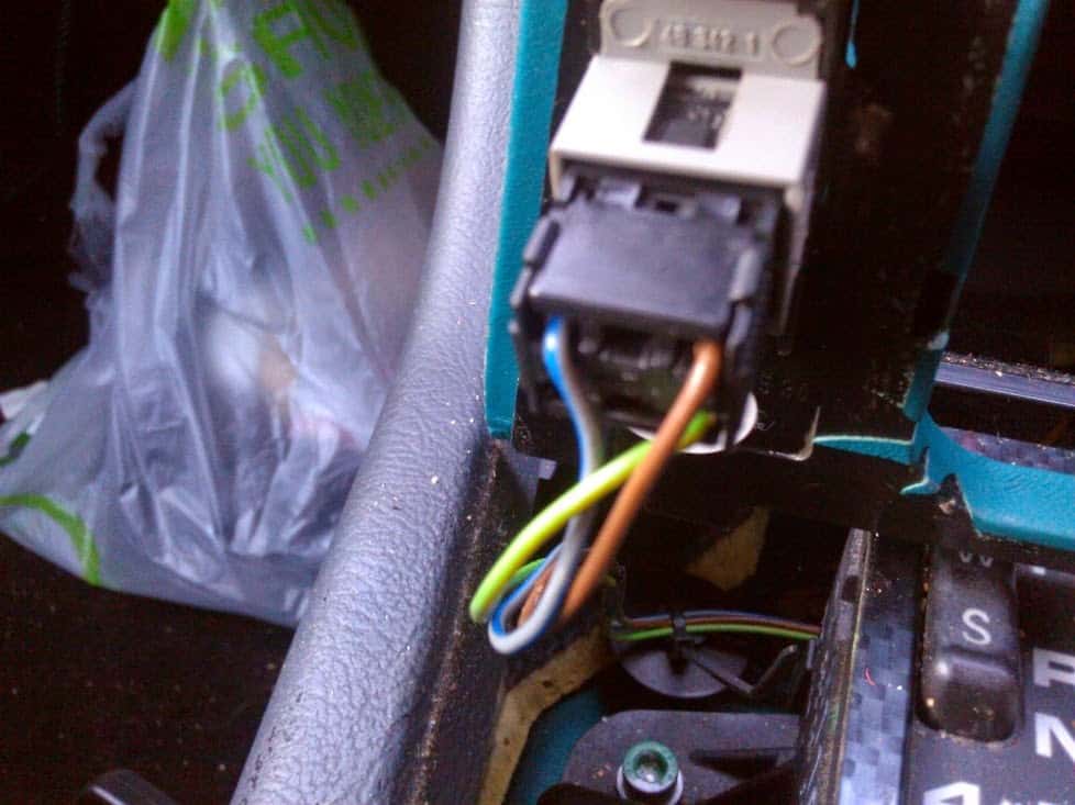
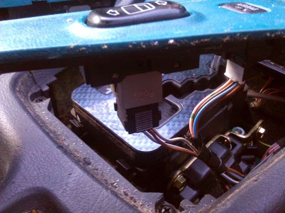
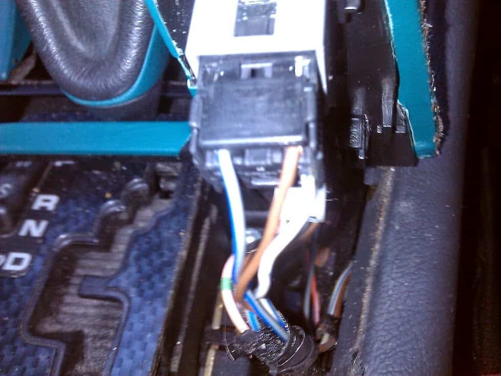
Following are some wonderful images and video sent by Mr. Mark, backs up the above discussion, and provides a clearer view of the involved operations.
Image and video courtesy: Mr. Mark Rothwell
Wiring Correction
A closer inspection shows that the modified circuit of the door close optimizer sent by Mr. Mark needs a major correction otherwise it won't work as intended.
The issue is in the termination of the 1000uF capacitor to the car relays.
Since the capacitors and the circuit relay are designed for a dual polarity function, needs to be implemented such that the car relays are able to switch momentarily in response to both ON/OFF conditions of the circuits DPDT relay.
The inclusion of a simple bridge diode network in between the capacitor outputs and car relays effectively solves the issue as shown the following finalized diagram
