
In this article I have explained how to build small electronic circuit projects suitable for beginners, young hobbyists, school students, who are new to electronics and are at the initial learning stage.
Which Circuit Projects are Suitable for the Beginners?
Warning: In this article there are a few circuits which are not isolated from AC mains. These circuits must be tried only under the strict supervision of an expert in the field of electronics. The author of this website cannot be held responsible for any accidents, whatsoever.
The circuit projects that are small in terms of number of component count, and are easy to understand, easy to build and troubleshoot are specifically recommended and suited to all beginners in the field of electronics.
Therefore, circuit projects that are specifically suitable and recommended for all beginners in the field of electronics and school students must include the following features:
- Must be Useful and Enjoyable
- Technically sound
- Safe to Handle (a few circuits explained here are not safe for the beginners, therefore these circuits must be tried only under the strict supervision of an expert.)
- Easy to understand
- Easy to build
- Easy to troubleshoot
- Easy to maintain
Since the constructors are supposed to be beginners in the field of electronics, all the circuits presented here have been meticulously selected so that they are easy to understand and easy to build.
Another important factor is that, all the circuit projects discussed below include minimum number of components so that the circuits can be built without errors, and if an error occurs, it can be rectified quickly.
Without any further ado, let's begin and first find out which hand-picked circuit projects for the beginners are included in this article, here's the complete list:
LED Projects:
- Simple Adjustable Lantern
- LED Flashlight
- LED Strobe light
- LED Bulb
- LED String Light
- LED Pendant
Transistor Circuits for School Science Exhibition:
- LED Flasher: Single transistor, Two transistor
- Rain Alarm
- Transistor Latch
- Burglar Alarm
- Water Level Indicator
- Transistor Voltage Regulator
- Current Limiter
- Transistor/Diode Temperature Sensor
- Simple Two Transistor Inverter
- Transistor Chaser
- Non-Contact Mains Hum Detector
- Transistor Touch Sensor
- Transistor Relay Driver
- Sound Activated Relay Switch
- Li-Fi Circuit
- Buzzer Circuit
- Wire Continuity Tester
- Bedroom Lamp Timer
- Music Level Indicator Circuit
- Transistor Solar Cell
- Emergency Light
Simple Timer Projects
- MOSFET Timer
- BJT Delay ON Timer
- BJT Delay OFF Timer
- IC 555 Timer
- Long Duration Timer using Two Transistors
Oscillator Circuits
- Transistor astable Oscillator
- Simple Transistor Clock Generator
- IC 555 Oscillator
- IC 741 Oscillator
DIY Amplifier Circuits
- LM386 Amplifier
- Mini Audio Amplifier
- Simple 10 Watt Amplifier
Basic Power Supply Circuits
- LM317/LM338 Power Supply
- Simplest Bench Power Supply
- Transformerless Power Supply
Simple Battery Charger Circuits
- LM317/LM338 Battery Charger
- LM7815 Battery Charger
- 2N3055 Battery Charger
- Solar Battery Charger
LDR Circuits for Newbies
- Automatic Day Night Switch Circuit
- Dimmer Dipper Circuit
- Intruder Alarm Circuit
- Light Activated Remote Switch Circuit.
- Light Activated Relay Circuit
Wireless
- FM Transmitter Circuit
Detector Circuits
- Simple Vibration Indicator Circuit
- Magnetic Field Detector Circuit
Now, without wasting anymore time, I have explained in details how the above circuit projects which are specially designed for all newcomers can be built and implemented practically.
Simple Adjustable Lantern Circuit
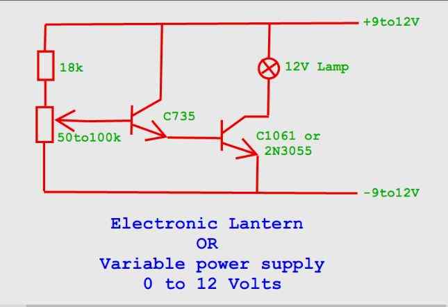
This simple adjustable lantern circuit can be a great project for any newbie, who can build this circuit within a few minutes and display the amazing effects by controlling the brightness of a 12V incandescent lamp, simply by rotating a potentiometer.
The project details were contributed by an avid reader of this blog, Mr. Ali
The parts required for the project are minimal:
Transistors
- 2N2222 = 1no
- 2N3055 = 1no
- Potentiometer 100K = 1no
- 1/4 watt resistor 18K = 1no
Video Representation:
The practical working of the above circuit can be witnessed in the following video:

LED Flashlight
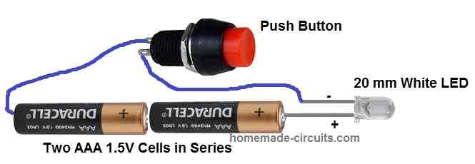
Today's white LED are very bright and can produce high power illumination with an input voltage of just 3V and an input current of hardly 20 mA. The wiring diagram of a simple LED flashlight or LED torch circuit is presented in the above diagram.
It simply consists of a couple of AAA, 1.5 V cells connected in series to produce 3V for the LED. The LED can be seen connected across the +/- terminals of the 3 V battery through a series push button switch. When the push button switch is pressed, the circuit is complete which causes the LED to illuminate brightly. A nice little project to begin with for all beginners in the field of electronics.
LED Strobe Light
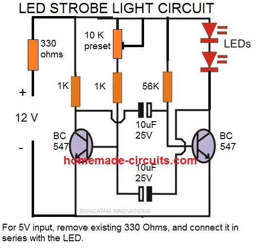
Strobe lights looks attractive because of their fast pulsating ON/OFF switching. The diagram above shows how to build an effective, adjustable strobe light circuit which can used in a bicycle by a school student and boast the fast flashing effect of the light to the viewers.
The circuit can also be used with a 3V supply, however for a 3V supply you may have to remove the 330 ohms resistor, and use only one LED instead of two.
The complete working model of the above strobe light design can be seen in the following video:

LED Bulb
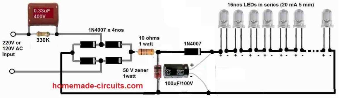
Warning: This circuit is not isolated from mains, so be extremely careful while testing it in switched ON position, to avoid a fatal electric shock. The whole assembly must be housed inside a sturdy plastic container for proper safety. BUILD IT ONLY IF YOU FULLY AWARE OF THE DANGERS OF ELECTRIC SHOCK AND KNOW HOW TO TAKE THE NECESSARY PRECAUTIONS AGAINST IT.
An LED bulb circuit can be a very intriguing project to build for any beginner or a school student, since this homemade project can be so useful and could be used for illuminating homes during night.
Although, the commercial LED bulbs are more sophisticated and employ an SMPS circuit, nevertheless the below shown LED bulb circuit could be built using capacitive power supply which is also equally efficient.
Note that the circuit can be customized as desired and any number of LEDs can be connected depending on the input AC supply level. For 220V, the number of LEDs can be up to 90 LEDs, and for 120V AC input the LEDs can be up to 45 nos.
The zener diode value will be equal to the value of the total forward voltage drop of the LEDs. For example if 90 LEDs are used then.
Total FWD drop = 90 x 3.3 = 297V.
So the zener diode value can be rated at 300 V.
Remember that the filter electrolytic filter capacitor value must be at least 25V higher than the zener value, if higher values than this is used, that will be fine.
LED Flasher with Single Transistor
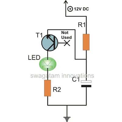
This simplest LED flasher can be quite fascinating to build for any new hobbyist since it requires only a single transistor connected in an unconventional way, to flash an LED with a 12V supply.
To achieve the flickering effect, the circuit makes use of the negative resistance factor of transistors.
The flashing speed might be changed by adjusting the value of R1 or C1 or both. However, the supply voltage must be more than 9V or the circuit would not function properly.
Two Transistor LED Flasher
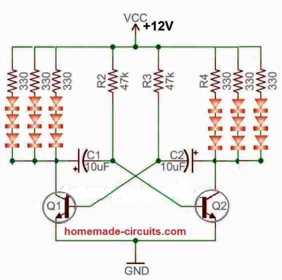
The next LED flasher utilizes a transistor astable circuit which alternately flashes the connected LED across the the two channels. The working is quite simple.
The capacitors C1, C2 charge and discharge alternately via resistors R2, R3 with the help of the transistors which also conduct alternately in response to the capacitors charging and discharging action. Due to this the connected LEDs across the collectors of the two transistors also flash ON/OFF alternately creating a cool decorative light effect.
Rain Alarm
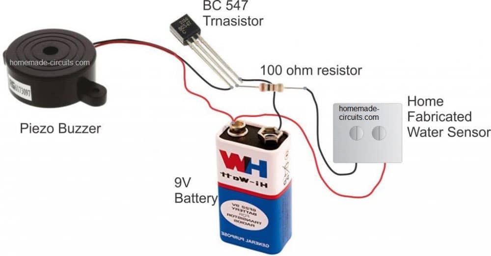
This simple rain alarm circuit which will switch ON a buzzer on detecting rain or water on its sensors can be a handy project for any newbie in the field of electronics.
The below circuit operates in a straightforward manner. As soon as raindrops fall on the sensing element, which is formed of screw tips, the water bridges over the screw tips, enabling a small electrical current to travel through the metal and activate the transistor's base. When this occurs, the transistor starts to conduct and amplifies the conductivity across its collector/emitter connections.
This causes the associated buzzer to turn on and start buzzing or blaring, signifying the start of rain outdoors and alerting the user to the situation.
Another simple rain alarm circuit can be seen in the following figure. Here, the circuit incorporates an in-built oscillator circuit using two transistors.
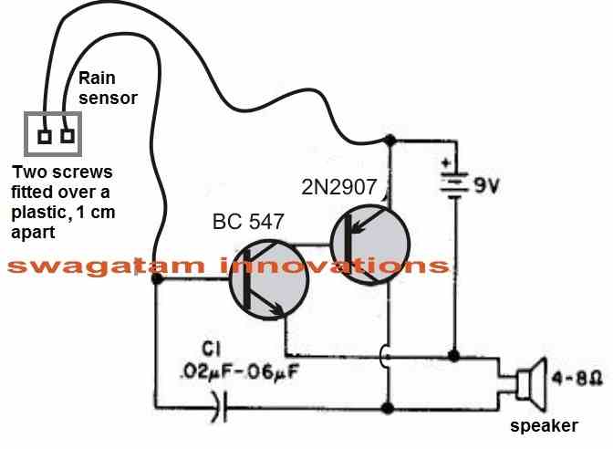
The oscillator circuit begins oscillating as soon as water is detected across the sensor device. When the transistor oscillator begins oscillating, the noise is generated through the attached speaker which alerts the user of a rain fall.
Transistor Latch
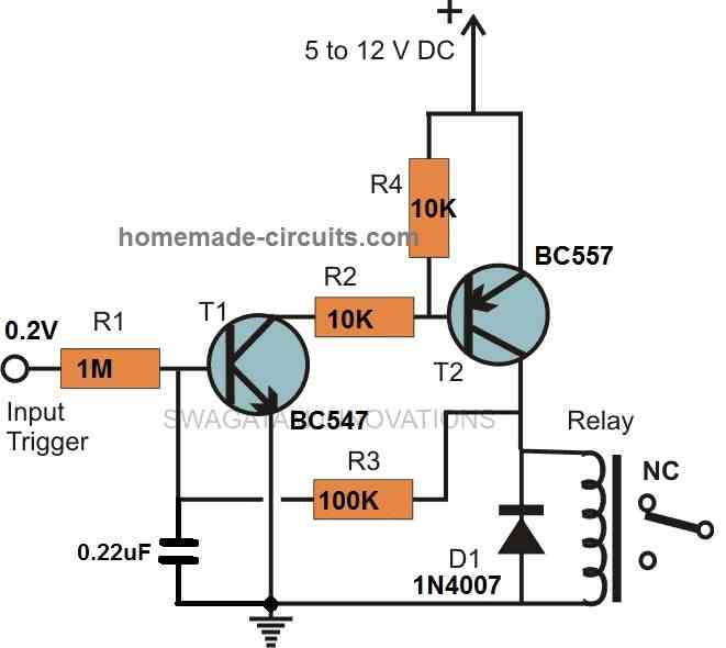
This transistor latch circuit will latch ON producing a permanent high output in response to a temporary input high signal and will remain in this state independent of the input signal for long as it is energized.
T1 and T2 are designed in such a way that T2 trails T1 to either conduct or halt the conduction based on the trigger received at T1's input, as indicated in the diagram.
T2 also works as a buffer, allowing it to respond more quickly to even the smallest inputs.
When a minute positive signal is provided to T1's input, T1 conducts immediately and drags T2's base to ground.
This activates T2, which quickly switches ON using the negative biasing provided by T1's conductance.
The addition of a feedback voltage via R3 changes the arrangement dramatically and aids in the generation of the needed characteristic in the circuit, namely, the BJT circuit instantaneously locks its output with a continuous positive supply.
Simple Burglar Alarm
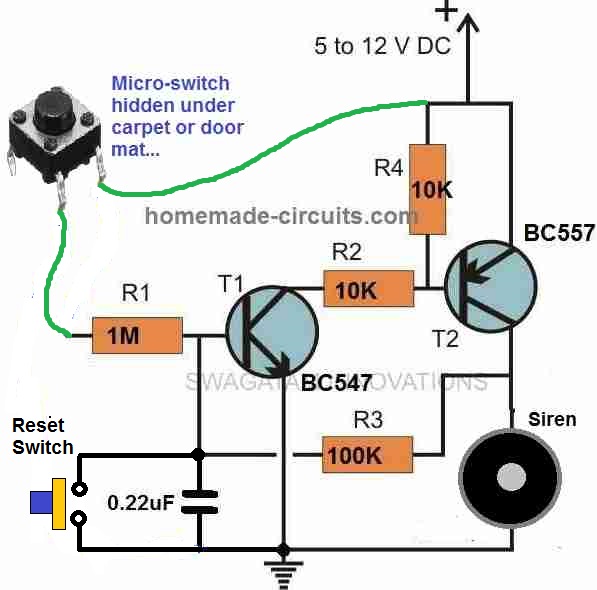
The above shown simple burglar alarm circuit is a good application example of the above latch circuit. Here, the input is replaced with a micro switch, whose one end is connected with the positive supply and the other end is connected with the input of the latch circuit. The output relay is replaced with siren unit.
Whenever an intruder accidentally steps over the micro switch briefly, the positive supply is applied to the input, which instantly triggers the latch circuit. The circuit now latches ON sounding the siren.
The siren keeps sounding in the latched mode until somebody, hopefully the owner comes and disables the burglar alarm either by switching OFF power to the circuit or by shorting the 0.22uF terminals.
Water Level Indicator
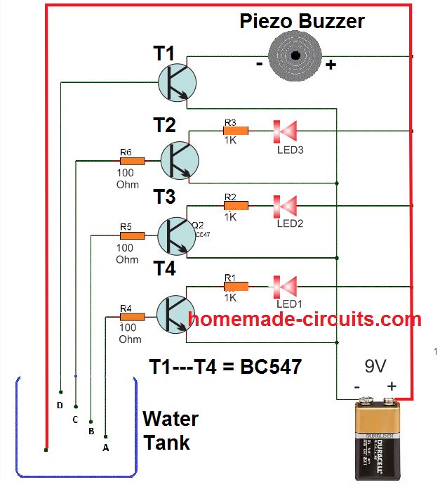
This simple 3 LED and one buzzer water level indicator circuit is another great small project for any beginner in electronics.
The idea is simple, as the water level rises, the bases of the respective BC547 transistors are connected with the positive supply through the water.
Minute current travel through the water and switch ON the bases of the respective transistor causing the LED to switch ON sequentially via the collectors of the transistors.
Simple Voltage Regulator
A new hobbyist's one of the important circuit requirement could be a genuine voltage regulator circuit. Although, voltage regulators with stabilized output can be quite complex to build, the single transistor version shown above can provide a highly stabilized with minimum part count.
The output voltage directly depend on the zener diode value minus the forward drop of the transistor. The formula is simple:
Output voltage = zener voltage - 1.2V
1.2V is the normal forward voltage drop of any standard Darlington transistor.
The input supply can be from a rectified transformer supply, rectified DC from an alternator, DC from a solar panel etc.
Current Limiter
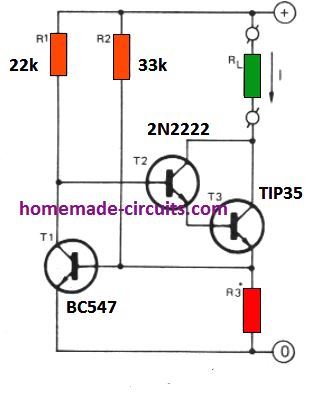
Just like the above stabilized voltage regulator circuit, a constant current circuit or a current limiter circuit can be also a valuable asset to any new electronic enthusiast.
The circuit above promises to deliver a voltage output that has a fixed or a constant current output due to the current limiting function of the circuit.
The working is simple. R3 determines the current or the amp value at which the current limiting is initiated by the circuit.
RL indicates the load. When the current through the load and R3 exceeds a set value, the potential drop across R3 increases to around 0.6 V which is enough to switch ON T1 BC547.
With BC547 switch ON, the base of T2, T3 Darlington pair is grounded which prevents them from conducting any further current through the load. This limits the current through the load and enables a constant, fixed current though the load, safeguarding it from an over current situation.
Simple Temperature Indicator
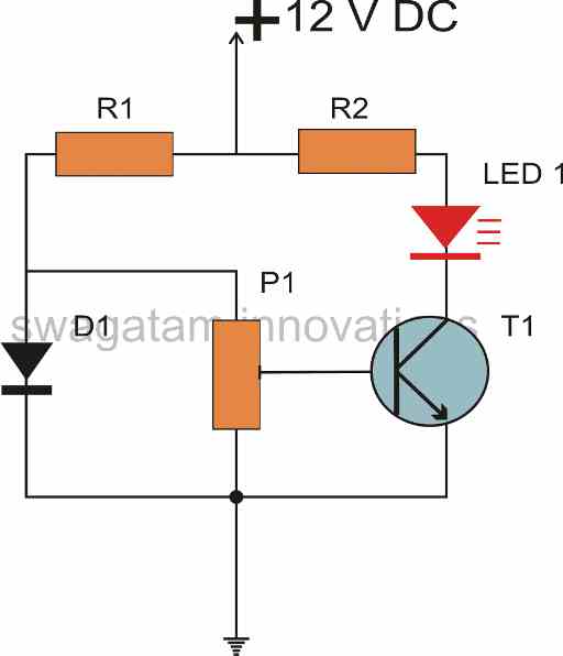
It is important to know for any school student who may be new to the field of electronics that semiconductor devices change there working characteristics in the influence of ambient temperature.
To precise, as the body temperature of a transistor or diode increases, they begin conducting more and more current through them.
In most cases this feature is considered to be a drawback, however it is also possible to exploit this feature of these components to make a nice little temperature indicator circuit.
The temperature indicator circuit shown above, demonstrates exactly how to do it.
In this design, a diode and a transistor are combined to create a bridge network.
The diode is supposed to be placed away from the heat at room temperature so that the voltage across it can be used as the reference value, In this situation the rising high temperature which is to be monitored is applied to the transistor.
The transistor's base emitter junction compares the heat with the heat on the diode and if it crosses the reference limit, the transistor begins conducting more and more until the LED is illuminated, indicating the rise in the temperature of the source.
P1 can be a 250 ohm preset, R1 and R2 can be calculated using the following formula:
R1 = (V - 0.6)/0.005
R2 = (V - 1.5)/0.015
Here V is the input supply voltage, 0.6 refers to the forward voltage drop of the BJT, and the figure 0.005 represents the typical working current for the BJT.
Simple Inverter
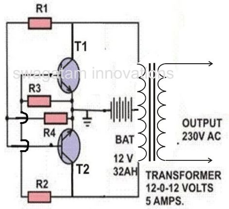
Inverters are normally considered to be a difficult project for any newcomer in the field of electronics. However, the above shown simple cross-coupled inverter can prove this wrong. It is a very simple design using just a couple of power transistors and a few high watt resistors.
Even though it is simple it can generate a formidable power output of 220V from a 12V automobile battery and can be used for operating power electrical tools such as soldering iron, lamps, small drill machines, table fan etc.
- R1, R2= 100 OHMS./ 10 WATTS WIRE WOUND
- R3, R4= 15 OHMS/ 10 WATTS WIRE WOUND
- T1, T2 = 2N3055 POWER TRANSISTORS (MOTOROLA).
- TRANSFORMER= 9- 0- 9 VOLTS / 8 AMPS or 5 amps.
- AUTOMOBILE BATTERY= 12 VOLTS/ 10Ah
- Transistors must be mounted on large finned type heatsinks
Simple LED Light Chaser

If you are a new hobbyist and are looking for creating a decorative LED lighting quickly using a few number of components, then this 3 transistor/LED light chaser circuit project is just for you.
Once connected and powered, the LED will illuminate sequentially one after the other creating a running LED light like effect.
Non-Contact Mains Phase Detector
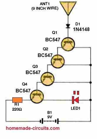
We have normally seen an AC mains tester in the form of a thin screwdriver with a neon bulb placed inside the handle of the screwdriver.
The tip of the screw driver is supposed to be touched with the mains LIVE wire so that the neon bulb can illuminate to indicate the presence of the LIVE mains. This is a traditional type of low tech device for testing mains phase, which requires a physical contact of the device with the mains wire.
The electronic version shown above is much sophisticated as this electronic phase tester can detect the presence of mains phase in a wire from a distance of a few cm above the wire, and does not require a direct contact with mains wire.
The design is built using a handful of general purpose transistor in Darlington mode where each one transistor's emitter is connected to the base of the next transistor allowing the total gain of the transistors to be in millions.
Due to its extremely high gain and a floating base input, this floating base acts like an antenna and is able to detect the 50 Hz or 60 Hz frequency of the mains LIVE from some distance and indicate the presence of the LIVE mains in the wire.
Touch Sensor
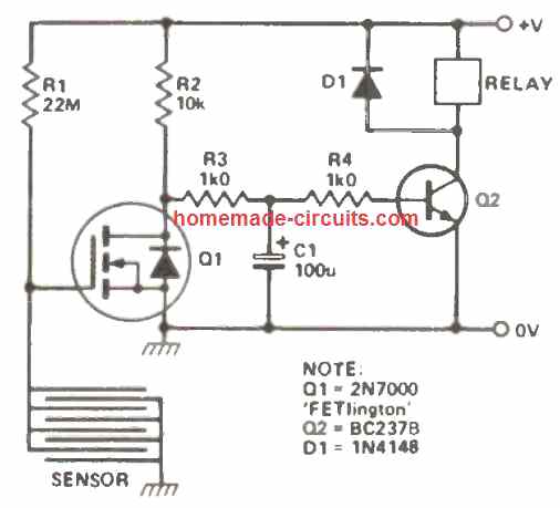
This is another simple circuit project that will activate a relay when the touch sensor is touched with finger. Normally the FET is in switched ON position due the R1 resistor providing the biasing voltage to the FET gate. With Q1 switched ON, the base of Q2 is grounded via the FET drain, which means the relay is kept switched OFF.
When finger is placed over the sensor mesh plate, the gate of the FET gets grounded, which causes the FET to switch OFF. With FET switched OFF, Q2 can now get the base bias via R2, R3, R4, and is allowed to switch ON the relay.
Due to the presence of C1 some charge is stored in it which allows the transistor and the relay to remain in the switched ON condition for sometime even while the finger is removed from the touch sensor plate.
Relay Driver
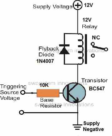
A transistor relay driver circuit is perhaps the most important basic circuit that a beginner in electronics must learn. It is important because this circuit can be universally interfaced with any small signal source to activate a relay safely and correctly, so that a heavier load can be switched across the relay contacts.
In the circuit diagram shown above, we can see a transistor being used in the common emitter mode with a relay coil connected across the positive supply and the transistor collector.
When a small voltage above 0.6 V is applied across the base emitter of the transistor, the transistor is quickly activated, which in turn causes the relay to switch ON.
A free wheeling diode connected across the relay coil ensures that whenever the relay coil is switched off, the resulting high voltage back emf from the relay coil is shorted out through the diode.
This further ensures that this back EMF from the coil never gets a chance to pass through the emitter/collector terminals of the transistor which otherwise could cause a permanent damage to the transistor.
Although the base resistor value is not critical, and could be figured out with some trial and error, the following formula can be used for determining its precise value.
Vin = (Vs - 0.7)HFe / Collector Current
Where Vin is the input signal to the transistor base, Vs is the relay supply voltage, HFe is the forward current gain of the transistor, and collector current is current spec of the relay coil which can be determined through Ohms law as given below:
Load current or relay coil current = Vs / Coil Resistance
Sound Activated Relay
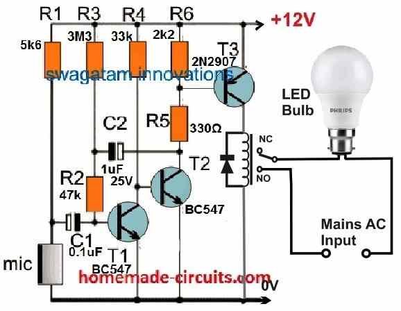
This can be a great fun project for any school student for his or her school science exhibition. The shown AC mains bulb will light up for some seconds each time a clapping sound is made near the MIC or within a distance of about 2 meters from the MIC.
The value of C2 determines how long the bulb will remain switched ON and then switch OFF.
This simple sound activated clap switch circuit uses only 3 transistors, a MIC, and some passive components but works vert effectively, and is very sensitive to loud sounds.
Li-Fi Circuit
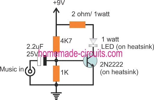

How amazing it can be for a school student to build a circuit which may be able to send data such as PWMs, or even music frequencies through light waves across some distance inside a dark room, wirelessly?
This simple Li-Fi circuit, as the name suggest is light-fidelity circuit which has a transmitter and a receiver. The left side single transistor circuit is the transmitter, which accepts a music or PWM frequency and converts it into light waves through a proportional illumination of an LED.
The right side circuit works like an audio amplifier with a solar cell as the input sensor. The frequency modulated light waves from the transmitter travel through air and strike the solar cell.
The solar cell converts this frequency into electrical impulses, which is amplified by the 2N3055 amplifier circuit and the frequency is demodulated and reproduced on the connected loudspeaker.
Simple Buzzer
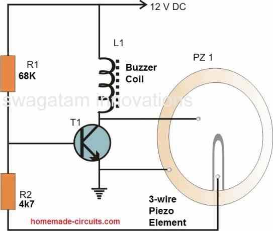
Piezo buzzers today are very popular. They are used in almost all electronic devices which need to produce a signalling sound. Although, these buzzers are very efficient and can generate loud beeping sound, making these buzzers is really simple.
To make a piezo buzzer you will only need a transistor, a few resistors, a buzzer coil, and a 3-wire piezo element.
Once procured, you can join them together with the help of the above diagram to create a buzzing piezo buzzer circuit.
The only problem with these units are the sticking procedure of the piezo element inside their housing. It has to glued with a silicone paste over a specially molded plastic enclosure for generating optimal sound output.
Wire Continuity Tester
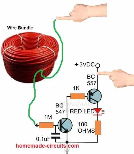
Another simple electronic circuit project suitable for all beginners is shown below, which is a simple continuity tester circuit. It works with a couple AAA cells in series or with a 3V DC, and can be used for testing the continuity of wire bundles or long wire networks quickly.
For checking the continuity of wires, the user has to touch the +3V supply with one hand finger, and touch one of the wire ends with other hand finger, while the other end of the wire hooked up with the 1M resistor end.
Bedroom Lamp Timer
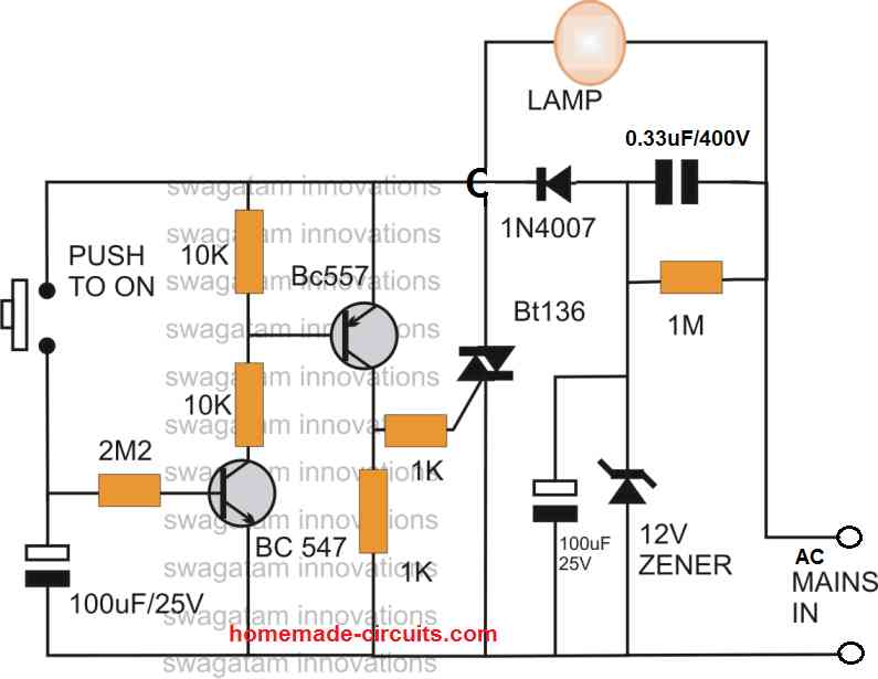
The simple bedroom timer circuit explained is very interesting and useful but it involves the mains AC with it. Therefore any new hobbyist building this circuit must be particularly careful not to touch the circuit with bare hand while it is in powered and in uncovered condition.
The working of the circuit is actually simple. When the push button is pressed, the 100uF/25V capacitor charges up and it starts supplying the bias current to the BC547 via the 2M2 resistor, even while the push button is released by the user.
As the capacitor supplies the bias voltage to BC547, it remains switched ON, which in turn causes the BC557 to switch ON.
With BC557 switched ON, the triac also switches ON through the gate current obtained via the BC557 collector.
The above procedure switches ON the lamp, and continues to glow.
However, as soon as the charge inside the 100uF capacitor completely depletes, the transistors are no longer able to hold there conducting positions.
The transistors now switch OFF after some delay provided by the 100uF charge, which turns off the triac, and the lamp is also extinguished.
The lamp remains extinguished until the push button is pressed yet again.
The 100uF and the 2M2 values determine the delay OFF time for which the lamp continues to glow and shut off.
Music Level Indicator
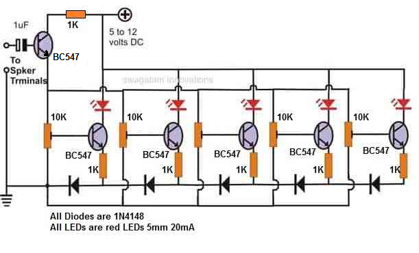
I built this music level indicator circuit in my school days and I was so amazed and proud to see the LEDs dancing to fro in response to the music frequencies.
The circuit actually consists of 5 identical transistor amplifier stages connected in common emitter mode. The sequential LED illumination in response to rising and falling music levels actually happens due to the 1N4148 diodes, which are arranged serially across the emitters of the transistors.
Since each diodes drops about 0.6 V across them, the LEDs illuminate with a lag of 0.6 V in response to the increasing and decreasing music level voltages.
The presets also play an important role, and they decide at what music levels the transistors need to conduct to illuminate the LEDs.
If you don't want to include the presets, you can simply replace them with a 10K/10K potential divider network, and the music level indication will still work.
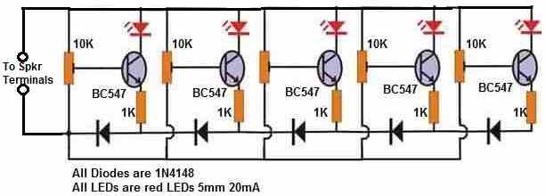
The above design can be further simplified as shown in the following figure:
Solar Cell from 2N3055 Transistor
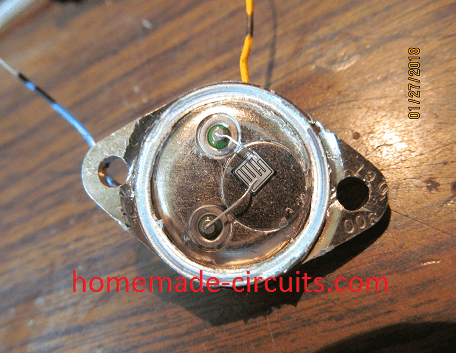
Making a simple solar cell at home can be a lot of fun for any electronic enthusiast. But how can that be done?
Answer is simple, just take a working 2N3055 power transistor from your junk box, grind off the top cap of the transistor carefully, as shown in the above left side figure, making sure the internal circuit is not damaged.
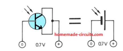
Next, as shown the below right side figure, simply join the transistor's emitter/collector pins together to form the positive output and the body collector can be used as the negative output.
Once, the above procedures are finished, exposing the cut off area of the transistor to sunlight would instantly start generating around 0.7 V across the positive/negative outputs of the transistor.
Emergency Lamp

Warning: This circuit is again not isolated from mains AC therefore is extremely dangerous to touch in an open and powered condition. Users are advised to take all the necessary precautions while handling or testing these circuits.
How about building an electronic gadget which can be plugged in to your mains AC socket, and whenever the AC mains fails, an LED illuminates automatically to light up your home.
The emergency lamp circuit shown above will do exactly this.
The above circuit can be further upgraded with an LDR, so that the emergency lamp does not activate when there is sufficient ambient light available. The emergency activates during a mains failure only when the surrounding is completely dark.

MOSFET Timer
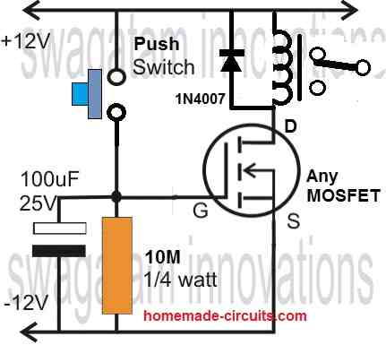
A very good MOSFET based timer circuit can be built using the circuit as indicated below. It works in this way.
When the push button is pressed and released, the 100 uF stores the 12 V supply in it and switches ON the MOSFET via this stored voltage.
The MOSFET now switches ON, and toggles ON the relay.
The capacitor now slowly discharges through the 10 M resistor, and when the voltage across the capacitor and therefore across the MOSFET gate/source drops below 5 V, the MOSFET begins turning OFF and subsequently switches OFF the relay.
The time for which the MOSFET and the relay is kept switched ON is determined by the values of the 100 uF capacitor and the 10 M resistor.
The biggest advantage of using a MOSFET is its infinitely high gate impedance, which prevents the 100uF from discharging via the MOSFET gate.
High gate impedance additionally allows the 10 M resistor to be extremely big, even as big as 50 M, which means that the time delay of this MOSFET timer circuit can be increased to very long intervals.
BJT Delay ON Timer
A delay ON timer refers to a timer circuit that delays its output switch ON once triggered with an input signal. The circuit above depicts a simple delay ON circuit project.
When power is switch ON, the relay does not operate immediately. The relay switches ON after some delay as determined by the values of R2 and C2.
BJT Delay OFF Timer
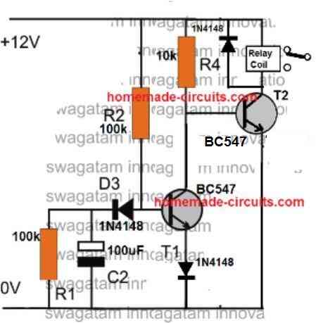
A delay OFF timer is the opposite of a delay ON timer. In a delay OFF timer the output of the circuit switches ON quickly in response to an external trigger and then switches Off automatically after some delay.
The figure above shows how to build a delay OFF timer circuit.
When the power is switched ON, the relay is switched ON immediately and then after some delay the relay switches OFF. The delay off time is determined by the values of R2 and C2.
IC 555 Timer
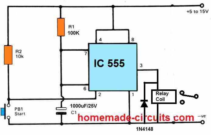
A very IC 555 timer project in the form of a simple delay timer circuit can be seen in the diagram above. IC 555 as we know is an extremely versatile IC which can be customized to build many outstanding and useful hobby and leisure projects for all beginners and school students.
The circuit is basically a IC 555 monostable circuit. When the push button PB1 is momentarily pressed and released, the relay at the output is immediately activated. The relay stays in the activated mode for a some time period which is determined by the values of R1 and C1.
The output delay interval can be calculated using the following formula:
T = 1.1 x R1 x C1
where, R1 should be in Ohms, and C1 in Farads.
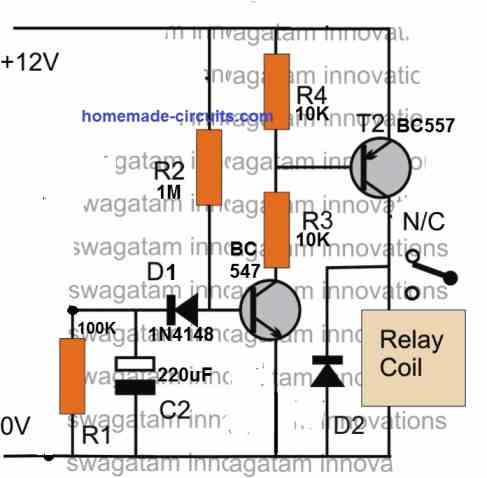
Long Duration Timer using Two Transistors
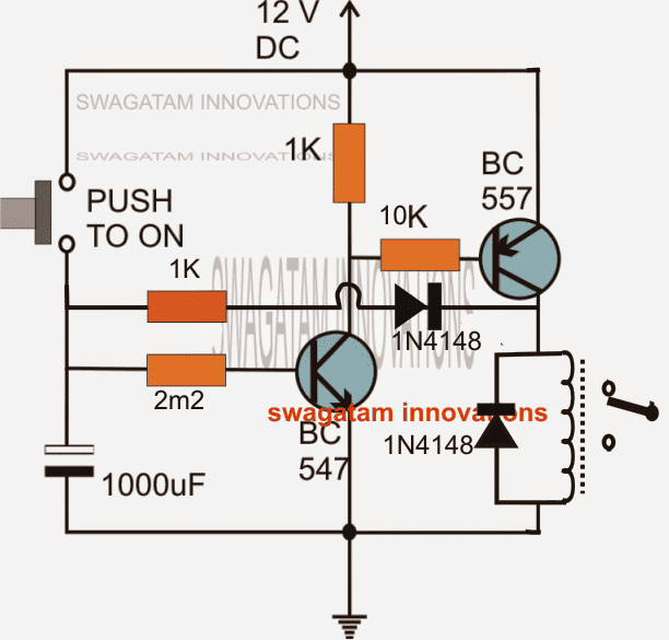
A reasonably long duration timer in the range of 2 to 3 hours can be effectively built using the simple two transistor circuit, as depicted in the above figure.
When the push button is pressed briefly, the 1000uF capacitor is fully charged, and the NPN BC547 transistor is triggered, maintaining the position even after the switch is disengaged. This is because of the 1000uF capacitor slowly discharging through the 2M2 resistor and the NPN emitter.
When the BC547 is triggered, it also activates the PNP BC557, which activates the relay and the attached load.
The foregoing scenario persists so long as the 1000uF is not discharged below the BC547 transistor's cutoff threshold values.
The inclusion of the 1K/1N4148 network instantaneously changes the circuit into a very accurate long duration timer.
The 1K and 1N4148 connections guarantee that once the transistors break the latch because of inadequate charge in the capacitor, the leftover charge within the capacitor is compelled to discharge completely through the relay coil via the aforementioned resistor/diode connection.
The above feature ensures that the capacitor is entirely drained and depleted for the next subsequent cycle, allowing the circuit to begin afresh.
Transistor astable Oscillator
A couple of circuits which are already explained above are the best examples of transistor astable circuits. These are: 1) LED strobe light, and 2) Two transistor LED Flasher.
The two transistor sections of the circuit oscillate and switch ON/OFF alternately due to the alternate conduction of the transistors in response to the alternate charging and discharging of the capacitors.
Simple Transistor Clock Generator
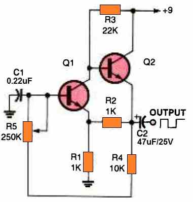
We can see a fantastic small square-wave oscillator circuit in the schematic above. This is one of the best electronic projects for the youngsters. Here, two common NPN transistors are directly linked to provide an adjustable speed oscillator that operates between a few hertz and many thousand hertz.
The result is a fast-rising and fast-falling waveform that may be used in circuit applications such as clocking tasks or other situations where a clean waveform is necessary.
By lowering the value of C1 or raising the value of the capacitor, the oscillator's frequency range could be increased or decreased, respectively.
IC 555 Oscillator
An IC 555 oscillator can be built by configuring the IC in its basic astable multivibrator form. More on this can be found in this article
IC 741 Oscillator
Just like transistors, and IC 555, the IC 741 can be also used for configuring customized oscillator circuit. More information on this can be accessed by reading this article.
LM386 Amplifier
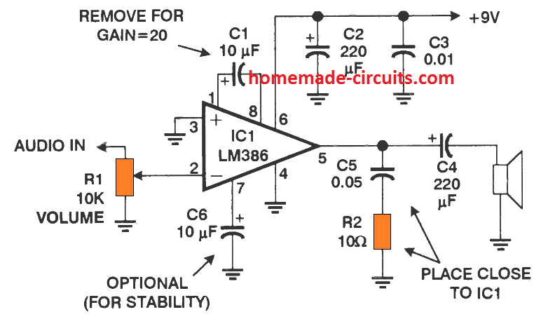
The LM386 based amplifier circuit is perhaps the smallest possible Hi-Fi single chip audio amplifier circuit available. The best thing about this IC is that you can customize to build a various types of audio based circuits such, microphone amplifier circuit, bass boost amplifier circuit, simple AM radio circuit etc.
Another great alternative to this amplifier design is the circuit using the IC LM4862
A basic version amplifies with a gain of 200, as shown in the above figure
Mini Audio Amplifier
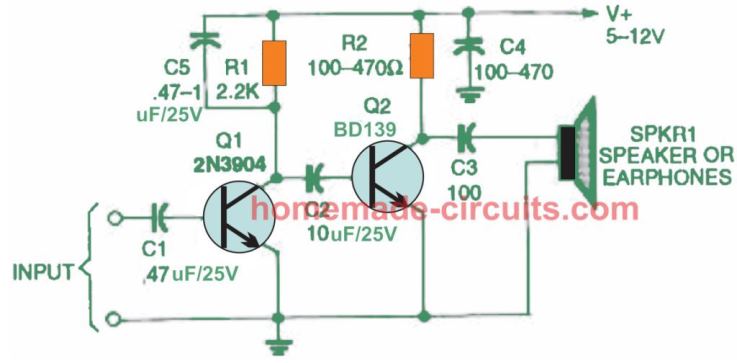
A mini audio amplifier circuit can be a great hobby project for any beginner or a school student. I already have a full collection of mini audio circuits projects in this blog.
However the smallest possible audio amplifier among them is the one which is shown below:
Any music input above 20 mV can be amplified by this circuit to reasonably loud audio level through the connected loudspeaker
Simple 10 Watt Amplifier using TDA2003 IC
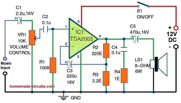
This is another great audio amplifier project which can be quickly assembled and implemented by any new hobbyist or a school student.
The circuit utilizes a single power IC TDA2004 which has all the Hi-Fi circuit ingredients built-in, which means you just have to attach a few passive external components with this IC to produce a genuinely loud and Hi-Fi music amplification over the connected loudspeaker.
The maximum output wattage that can be achieved from this is around 10 watts
The input port of the TDA2003 is linked to ground through a 100 K resistor on pin 1. A 10-kilo-ohm potentiometer (VR1) and capacitors C1 and C2 are used to feed the music signal to pin 1 of IC1.
The volume is controlled via the potentiometer VR1. IC1's pin 3 is linked to ground. Pin 4 is the speaker's output terminal, which is linked to one of the loudspeaker's terminals via a 470F/16V capacitor (C5). A 0.1F capacitor (C4) and a 1-ohm resistor link it to ground as well (R4).
Switch S1 connects pin 5 of IC1 to the +12V power source. A 12V battery or a 12V DC converter can be used to supply power to this 10 watt audio amplifier circuit. For IC1, a sufficient heatsink should be used.
LM317/LM338 Power Supply

The versatile LM317 and LM338 ICs can be used for building highly regulated and stabilized circuits using bare minimum number of components.
The result is a power supply circuit whose output can be continuously varied right from 1.2 V to a maximum of 35V. The other useful features of this power supply is that it is virtually indestructible as the IC has internal built-in protections such as output short circuit protection, over load protection, and over heat protection. The circuit can be also upgraded with a transistor for delivering a constant current output.
A basic LM317 based power supply can be witnessed in the diagram shown above. This can be very useful and versatile power supply project for any beginner for testing and powering other electronic projects.
The LM317 has a maximum capacity of delivering 1.5 amps output while LM338 can be used to get a maximum output of 5 amps. The LM317 and LM338 ICs are pin to pin compatible and replaceable.
LM317 20 Amp Power Supply
For powering high current circuit applications that may require upto 20 amp current, the above circuit can be perfectly upgraded into a high current LM317 power supply as shown in the following image.

As can be seen, the circuit transforms the 1.5 amp output from the LM317 into 20 amp output capability through the use of 6 parallel 2N3055 transistors configured in the emitter follower mode.
The output voltage can be adjusted between 3 V and 20 V when the input supply is around 24 V.
Simplest Bench Power Supply
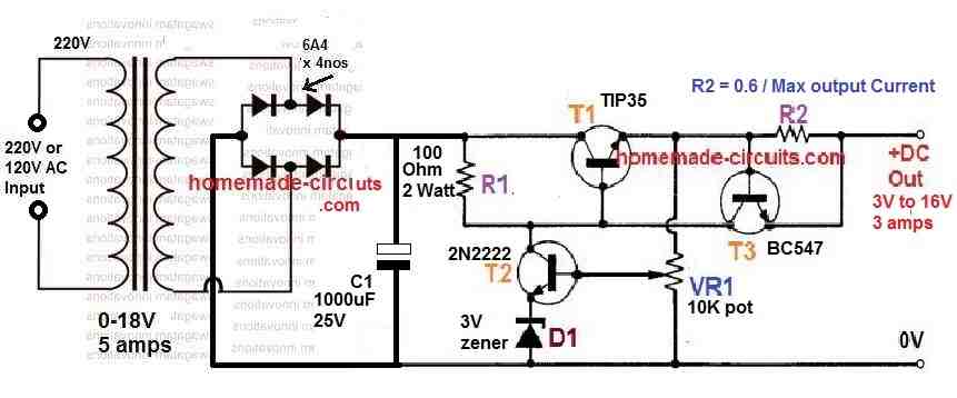
Although the above IC LM317 based power supply circuits can work like an excellent bench power supply units, making one using discrete components can be even more interesting.
The image above shows a simple yet very effective bench power supply built using a few transistors, diodes, resistors and a transformer.
The great thing about this bench power supply is that it allows the user to learn the working of each of the components discretely, and therefore the circuit becomes extremely customizable by the user.
The VR1 is used to adjust the output voltage between the zener voltage value and the maximum bridge output value. T3 and R2 together work like current limiting network, to ensure the current is never exceeded above the preset limit.
Transformerless Power Supply

The above explained power supply circuit require a transformer for stepping down the mains AC voltage to lower levels such as 12V or 24V or 50V. They require transformer since they are supposed to handle higher amounts of current in Ampere range.
However, for low current requirements in the mA range, a transformerless power supply generally can work well. A simple general purpose transformerless power supply circuit is shown below.
This design can deliver an output of fixed voltage between 3 V and 90V depending on the zener diode value which can be selected as per the output voltage requirement.
One big disadvantage of this type transformerless power supply is that, these are not isolated from the input AC mains, and therefore contains a floating high mains voltage which can inflict a lethal electric shock if the circuit is touched in an uncovered, powered condition.
The output current is decided by the value of the input capacitor which is a 0.33uF here. As a rule of thumb every 0.5 uF capacitor will be able to deliver an output current of 30 mA. This means a 0.33uF would be able to deliver an output current of around 20 mA.
WARNING: BUILD THIS CIRCUIT ONLY IF YOU ARE AWARE OF THE DANGERS OF MAINS AC AND KNOW HOW TO MAINTAIN EXTREME PRECAUTIONS AGAINST IT. BE EXTREMELY CAREFUL WHILE TESTING THIS CIRCUIT SINCE IT IS NOT ISOLATED FROM AC MAINS, AND CAN PRODUCE LETHAL ELECTRIC SHOCK IF TOUCHED DIRECTLY IN AN UNCOVERED AND POWERED CONDITION. MAKE SURE TO PROPERLY INSULATE ALL THE POINTED OR EXPOSED CONNECTIONS OF THE FINAL ASSEMBLY.
LM317/LM338 Battery Charger

A battery charger circuit is something every beginner in electronics might want to build in order to conveniently charge all sort of batteries from a lead acid battery to a Li-Ion battery.
A perfect battery charger circuit for charging virtually all types of batteries is shown below, again using the versatile LM317 or LM338 IC.
The output voltage can be adjusted using the R2 10 K pot, and the output current can be fixed by setting up the Rc resistor. For lead acid batteries the Rc formula will be as follows:
Rc = 0.6 / 10% of Battery Ah
For Li-ion the Rc formula will be:
Rc = 0.6 / 50% of Battery Ah
Since we do not have an auto cut off for this circuit, therefore it is recommended to adjusted the output voltage to slightly lower than the full charge level of the battery.
For 12V lead acid battery this can be around 14 V, and for a 3.7 V Li-Ion battery the output voltage could be set to 4.1 V for optimal, safe charging procedures.
2N3055 Battery Charger

A high current variable voltage battery charger can be built by upgrading a basic LM317 power supply as shown in the above figure.
Make sure to connect a 100 ohm resistor in series with the base of the 2N3055 (green wire), which is mistakenly not shown in the diagram.
Using this 2N3055 based charger circuit, any battery between 1 Ah to 50 Ah can be charged without any issues. The only factors that needs to ensured are: keep the output voltage slightly below the full charge level of the battery, and set the maximum output current to 10% of the battery's Ah value.
Solar Battery Charger
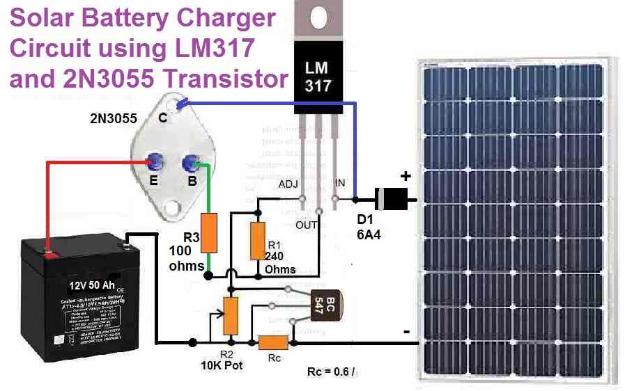
A simple yet extremely effective solar battery charger could be built simply by adding a solar panel to the above 2N3055 power supply circuit.
Since solar panel is also basically a DC power source, the transformer and the bridge rectifier can be removed from the power supply, and replaced with an appropriately rated solar panel.
Since the maximum output capacity of the above solar battery charger circuit around 5 amps, the solar panel can be also rated at 24 V 5 amps.
For charging bigger batteries, you can simply add more number of 2N3055 transistors in parallel, and upgrade the solar panel rating accordingly.
Automatic Day Night Switch Circuit
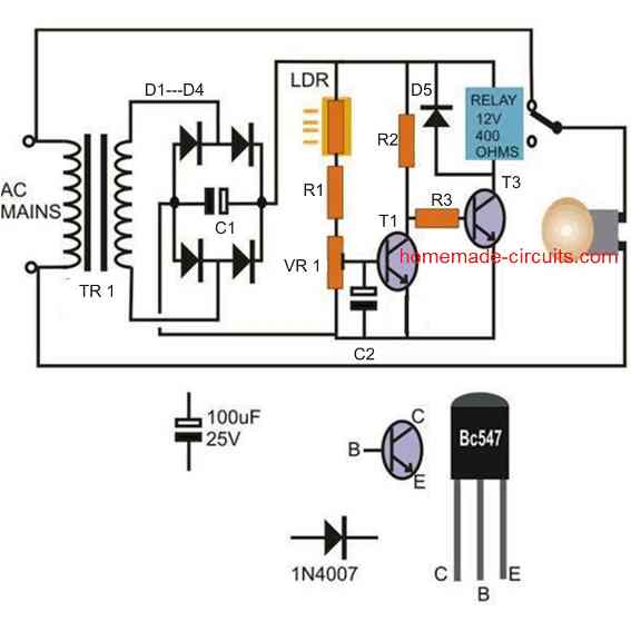
This is probably the best fun project a beginner in electronics can build and see it work practically.
This LDR based day and night activated automatic relay switch circuit can be used for switching ON and OFF, a 220V or 120V mains lamp in response to the daily sun rise and sun set activities.
During day time while ample ambient light is present, the LDR senses the light and keeps the transistors switched OFF, which in keeps the relay and the connected lamp switched OFF.
As soon as darkness sets in, and the darkness level falls below the preset level of the circuit, the transistors switch accordingly causing the relay to trip ON, and this instantly switches ON the connected lamp, illuminating the premises automatically.
Care must be taken to ensure that the light from the lamp does not fall on the LDR, otherwise the whole circuit might go into a random oscillation causing the lamp to keep flickering continuously.
- R1, R2, R3 = 4k7 1/4 watt
- VR1 = 10k preset
- LDR = any standard LDR having approximately 10k to 50k resistance in day light (under shade)
- C1 = 1000uF/25V
- C2 = 100uF/25V
- All diodes = 1N4007
- T1, T2 = BC547
- Relay = 12V, 400 ohms, 5 amp
- Transformer = 0-12V/500mA or 1 amp
Dimmer Dipper Circuit
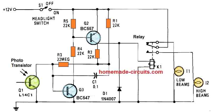
Any electronic novice or hobbyist who may interested to build a simple yet useful automotive product will find this simple head light dimmer/dipper circuit to be an excellent choice.
Instead of an LDR a phototransistor has been used here for sensing the light rays from an incoming automobile.
An automobile headlamp dimmer/dipper circuit is a device which is used to prevent head light beam os two opposite vehicles from interfering or disturbing the drivers view.
A headlamp dimmer dipper installed in a vehicle causes its head lamp to automatically switch from a high bright to a low bright filament mode whenever the head lamp beam from an opposite vehicle is detected. This allows the opposite side driver to visualize the situation and in course manually dip his vehicles lamp also.
Intruder Alarm Circuit

A very easy to build LDR based burglar alarm circuit is shown in the above image.
The circuit is supposed to be armed or switched ON, only once all the surrounding lights are switched OFF and there is complete darkness.
A potential burglar or an intruder cannot tread in total darkness, therefore the person will possibly come with a flashlight and will switch it ON to check out things around the area.
As soon as the light from his flashlight hits the LDR, its resistance will drop, which will cause the SCR agate to receive the required activation voltage and it will be triggered ON, sounding the alarm bell.
The alarm bell can be any 12V siren unit, capable of generating a loud siren like sound.
Our potential intruder will now hurriedly try to switch OFF his flashlight, expecting the alarm to turn off. However, the alarm simply won't turn off, since the SCR is now latched and can be turned off only by switching off the supply voltage, which could be perhaps only done by the owner..
Light Activated Remote Switch Circuit
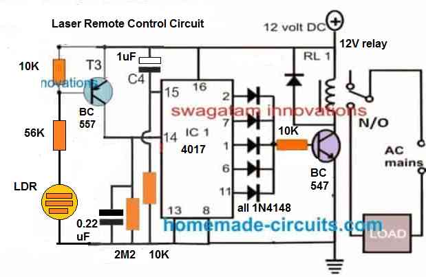
This is yet another great fun project that any school student can build and enjoy. The circuit is basically a light activated flip flop circuit which can be used to toggle an electrical load by toggling a laser beam on the LDR sensor of the circuit.
When a laser beam is focused on the LDR and switch ON/OFF, it causes the T3 BC557 to toggle ON OFF alternately in response to the laser beams.
This in turn causes the DC positive to alternately switch the pin14 of the IC 4017.
As we know when pin14 of IC 4017 is switch ON OFF, its output pins sequence from pin#3 to pin#11 and then it is reset back to pin#3.
When the output pins sequence, in the course it causes the connected BC547 and the relay to switch ON/OFF alternately in response to the laser beam switching.
When the relay toggles, the connected load which can be a lamp, a fan, a porch light also switch ON OFF.
Thus this simple laser activated switch can be effectively as a simple light activated remote control switch for controlling any electrical gadget simply by focusing and switching a laser beam on the LDR sensor.
Light Activated Relay Circuit
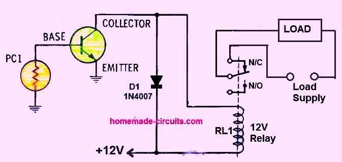
This is an intriguing automated light activated relay changeover circuit that can reliably transfer light beams from one light source to another by using just one transistor.
It may be used for a wide range of purposes, such as kid-friendly target games, morning wake-up calls, intruder alarms or an automatic street lamp circuit.
Simply connect whatever circuit you like to the relay contacts of RL1 and that's all. The remainder will be handled by the economical light relay.
It may be programmed to only activate a load (alarm or lamp) when the light ray on the photocell is interrupted or to indicate the opposite when light falls on the photocell.
How it Works
The working of this light dependent relay circuit is very simple. Let's say, during day time when light rays fall on the photocell PC1, a tiny potential difference is generated across the photocell.
This potential difference is sufficient to switch ON transistor, and the transistor T1 switches ON.
When T1 is switched ON, the relay is also switched ON, such that its contacts shift towards the N/O terminal of the relay.
The N/O contact being open keeps the connected load switched OFF. If the load is a lamp then the lamp remains switched OFF.
When darkness sets in, the light on the photocell decreases to a level where its voltage output is unable to keep the transistor T1 switched ON. Now, the transistor switches OFF.
When T1 switches OFF, the relay also switches OFF such that its contacts now shift towards the N/C contacts.
N/C contacts of the relay being connected with a load and a supply voltage turns ON the load. If the load is a lamp then the lamp turns ON. Meaning, the lamp turns ON as soon as there's sufficient darkness around the photocell.
Transmitter Circuit
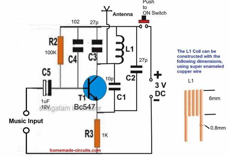
Perhaps one of the most enjoyable circuit project for any kid could be a circuit that would transmit voice or music signal wirelessly to an FM radio.
The FM transmitter circuit shown above will do exactly that.
Once built, the input of the transmit could be attached to any music source either from a cell phone or computer.
The music would then start transmitting in the air within the FM band range and could be received and reproduced by any nearby FM radio, after an appropriate tuning.
The maximum range of this transmitter is around 50 meters radial distance.
Simple Vibration Detector Circuit

When the attached meter is subjected to vibrations, its needle vibrates causing tiny electrical voltage to develop across the op amp input. This tiny potential difference is amplified by the op amp and is indicated through a blinking LED at the output.
It does seem a little strange to have a meter attached to a comparator's input pins rather than its output. However in this circuit, the meter is not being used to show an output.
You might be aware that a moving coil meter's needle is extremely sensitive to outside vibration and displacement.
Due to this, we use the meter as a vibration sensor, to create an output through the op amp. An analog meter works like a little dynamo in design. Inside the meter, a multi-turn electromagnet connected to the meter's needle is setup between the poles of a strong permanent magnet.
Any vibration on the needle forces the armature to oscillate within this strong magnetic field, which generates tiny electrical voltage across the winding of the meter armature.
In this circuit, the meter armature will generate tiny electrical signal in response to any motion or vibration. The signal from the armature is amplified by an LM339 comparator which causes LED1 to blink on and off as the meter needle goes back and forth. (Take note that all the unused pins of the LM339 must be connected to ground in whatsoever configurations that employ it.)
The meter's needle will be most sensitive when it is parallel to the vibrating source that surrounds it. Additionally, the mechanical zero scale of the meter could well be moved up and away from the end peg to increase sensitivity.
The type of meter that is used significantly affects the circuit's sensitivity.
The 0 to 50-microampere type of meter might be much more sensitive to small vibrations or motions compared to a 0 to 1-milliampere type of meter.
Magnetic Field Sensor Circuit

In this design the meter is swapped out with a relay coil to create a magnetic field sensor circuit, as described above. This setup is extremely susceptible to shifting magnetic fields. LED1 will light up if you pass a tiny permanent magnet across the attached relay coil.
With the magnet moving and the coil locked in place, the sensor operates similarly to the previous design using a moving coil meter. Any type of relay coil can be used in the circuit, however for best sensitivity choose a relay coil with the maximum inductance and highest resistance (around 400 ohms).
Installing a permanent magnet at a few inches away from the relay coil but parallel to the coil's pole can transform the circuit into a sensor capable of detecting a iron item travelling between the magnet and coil. Tiny AC voltage potentials is produced across the coil each time the magnetic field changes. These tiny electrical signals are amplified by the op amp, which in turn causes the LED1 to flicker on and off.
Over to You
Although the list can be unending, the above explained circuit designs are among the most popular and favorite easy circuit projects, specially designed for all beginners, and also for the budding school students who are passionate about electronic circuits.
But wait, this is not all, this blog is filled with a huge number of small electronics circuit projects which can be specifically interesting for all the beginners and the newbies, more info on this is given below:
Basic Electronic Circuit Projects
Simple Unijunction Transistor Circuits
How to Use Electronic Components
If you think I have missed a particular easy circuit project that needs to be included in the list, please feel free to comment in the below given comment box. You can also demand a specific diagram of your own choice and specifications, if possible I will try to design it and update it the above article.
Enjoy the circuits!!