In this post we study how to make a simple clap operated toy car circuit using a clap switch circuit and a MIC amplifier, to control its forward and reverse movements, in response to the claps of the user. The idea was requested by Mr, Zeeshan.
This clap operated toy car is will move in forward or reverse directions every time a clap sound is generated.
Circuit Objectives and Requirements
- I urgently need a circuit diagram. I need a circuit of a toy car which goes forward and reverse on the sound of clap.
- After switching on, car goes forward ( motor rotate clockwise).
- After a clap sound car goes reverse( motor rotate anti clock wise). and vise versa.
- In other words, toy motor change it's rotation from clockwise to anti clockwise and vise versa by clap sound. If possible make it using 3 or less pencil aaa cells.
- If yes please help me by providing me so.
The Design
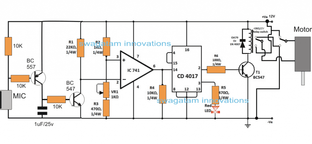
The above requested idea of a clap operated toy car circuit can be implemented using the following simple circuit:


The circuit is made up three basic stages: the MIC amplifier stage, the opamp comparator stage and an IC 4017 based flip flop stage.
The IC 741 is configured as a comparator and together with the IC 4017 it forms a basic clap operated switch circuit.
The BC557/BC547 constitutes the MIC amplifier circuit, we have used two transistors here to make the design highly sensitive to the clap sounds.
Whenever a clap sound or any similar sound is detected by the MIC, it instantly conducts and causes a low signal across its leads enabling the BC557 to trigger.
BC557 triggering forces the BC547 to conduct even harder and in the course brings the pin#2 of IC 741 to ground level or lower than the pin#3 reference pin of the IC. This action enables the opamp output to go high causing a positive trigger for the 4017 input pin#14.
The above functioning forces the IC 4017 to change states across its output pins #2 and pin#3 alternately with every clap sound detection.
The output from the IC 4017 can be seen connected with a relay driver stage consisting of a DPDT relay with its dual contacts configured with the toy car motors, and the supply rails.
The flip flop action from the IC 4017 output toggles the relay contacts across their N/C and N/O points, thereby causing the car motor to correspondingly rotate in cock-wise and anticlockwise directions in response to the subsequent clap sounds, and thus the car is able to move forward or backward accordingly.
In order to make this clap operated toy circuit make sure to wire the indicated relay contacts across both the motors of the car which may be attached at the front of the rear sides of the unit, and must have a gear box configured with the wheels.
Sir. I m going to make this circuit but I have some confession to take this circuit diagram. I can’t be understanding Relay connections. How many and which types relays r being used here. Relay code ?
Virendra, the relay is a DPDT relay which stands for double pole double throw, and has two sets of identical contacts which operate together.
Sir , in place of BC 557 transistor can we use BC547
& What’s main difference bw them
Shiva, you can try it, make sure to connect the emitter towards the base of the other BC547
hellow sir i want to make a home automation system as my last year project please refer me one and your website is fandastic one
Thank you tapan, presently I do not have a full-fledged home automation circuit, possibly I'll try to present one soon,
4017 is wrong! it should e a 4013 type flip/flop
Swagatam – I'm looking for a timer circuit. The type that is used in electronic candles (and christmas decorations) to turn them on 4-5 hours and then off 20-19 hours. Then repeat that on/off cycle everyday. Those electronic candle circuits are small, about the size of a US dime, and can handle 3 to 6VDC. Am not asking you to design one – if you have a similar one in your list…just point me towards it. Love your web site !!
thanks dean, I think you can try the following concept, you can use SMD parts to make it really compact:
https://www.homemade-circuits.com/2012/04/how-to-make-simple-programmable-timer.html