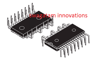
In this post I have explained the datasheet, and the pinout specification of the IC STGIPN3H60 from ST microelectronics, which is perhaps the slimmest and the smartest 3-phase IGBT driver IC featuring in-built IGBTs, rated to work with 600V DC bus and upto 3 amp current, that's equivalent to almost 1800 VA handling power.
3-Phase IGBT Driver IC with Advanced Features
In this website so far we have mostly discussed and incorporated the IRS2330 (or 6EDL04I06NT) for implementing a given 3 phase driver application such as a 3 phase inverter or a BLDC motor controller, and assumed this to be the easiest option using ordinary discrete components.
However with the advent of this new more compact, slim and smart 3-phase driver IC STGIPN3H60, the earlier counterparts appear to be quite outdated, no surprise why this new IC is entitled with the name "SLLIMM" meaning small low-loss intelligent molded
module.
This is especially because the new IC STGIPN3H60 incorporates in-built IGBTs enabling the application designs to become extremely compact and hassle free while configuring the specified parameters.
Let's not waste any more time and quickly learn the main features, and specifications of this smart 3-phase driver IC.
Main Technical Features
1) The device is a 3 phase IGBT full-bridged driver rated at 600V, 3 Amp
2) Comes with in-built full bridge 3 phase IGBT circuit, along with freewheeling protection diodes
3) Features a low electromagnetic interference working
4) Comes with an under voltage lock out, and a smart shutdown feature
5) Offers a comparator for enabling over current and over load cut off protection.
6) Includes an optional opamp in-built for enabling an advanced protection system, if demanded.
5) Possesses an in-built bootstrapping diode.
We might find a few more outstanding features in the device but I will elucidate only the above main features through its pinout functions, for the sake of simplicity.
Application Areas:
The proposed IC can be used for making extremely efficient, and compact units as mentioned below:
3-phase phase inverters
3-phase BLDC motor controller
heavy lifting quadcopters
super efficient ceiling fans
E--rickshaws, and bikes
in robotics etc
Pinout description

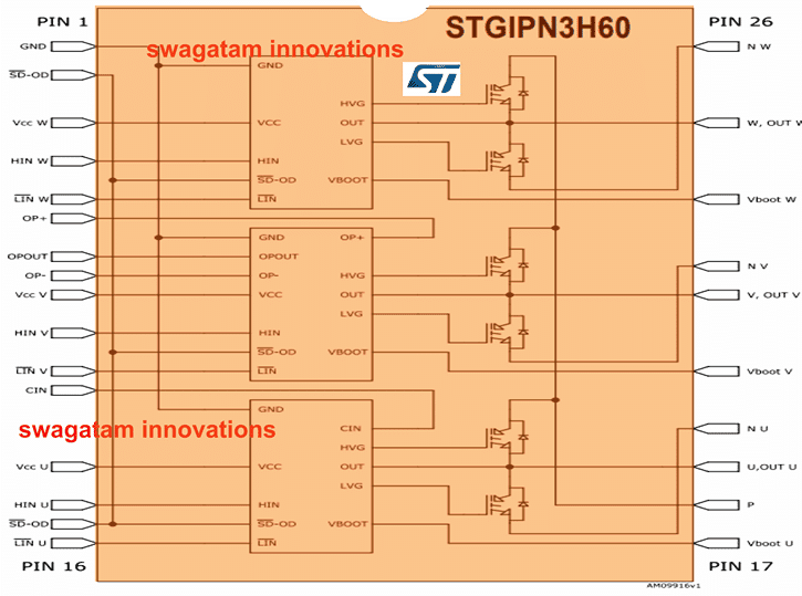
The figure above depicts the pinout diagram of the IC STGIPN3H60, which is a 26 pin DIL IC, we will begin the pinout functioning explanation from the left hand side of the IC.
Pin#1: It is the ground pin of the IC and needs to be connected with the ground supply rail.
Pin#2, 15: These are the SD-OD pins, any of which can be used for shutting down the device through an external sensor circuit for safeguarding the system from a possible catastrophic situation. A "low" signal on this pinout will execute the shut-down operation.
Pin#3, 9, 13: These are the Vcc supply voltage input pinouts, for the 3 internal driver modules and must be shorted together, and connected with a common +15V DC input.
Pin#4, 10, 14: These are the HIN inputs or the high side logic signal inputs, complementary to the LIN inputs or the Low side signal inputs. These pinouts must be fed with a 3-phase alternating 120 degrees apart logic signals from an external source or an MCU, for initiating the motor rotation.
Pin#5, 11, 16: These are the LIN inputs or the Low side logic signal inputs, complementary to the above explained HIN inputs and should be fed with alternating 3-phase low voltage triggering signals for initiating the motor rotation.
The HIN, and LIN input signals must be anti-phase to each other, meaning whenever HIN is high, the corresponding LIN must be low and vice-versa.
Pin#6, 7, 8: These are the non-inverting, output and inverting pinouts respectively of an internal spare opamp which can be suitably configured for executing a required advanced protection circuitry in case the system demands for it, otherwise these pinouts can be left unused, however make sure not to keep these opamp inputs open and floating, rather terminate these OP+, OP- pinouts through an appropriate configuration, to prevent instability across these pinouts.
Pin#12: It is the Cin or the comparator pin of an internal comparator stage, which facilitates processing of a sensed over-current or overload signal generated by an externally configured shunt sensing resistor.
Now let's move on to the right side of the IC and see how the indicated pinouts are designated to function and how these needs to be configured within a given driver application circuit.
Pin#19, 22, 25: These are the output pinouts of the IC, and needs to be connected straight with the specified 3-phase wires of a BLDC motor, regardless of whether the motor involves sensors or not. A motor having sensor wires can be also used with this IC.
In case the motor incorporates hall sensors, the sensor wires could be configured with the HIN/LIN pinouts, through suitable inverting gates, because the corresponding HIN/LIN inputs must be applied with anti-phase or opposite signals for correct operation of the motor, and that's why the signals from each motor hall effect sensors must be bifurcated into +/- using NOT gates for feeding the respective HIN/LIN complementary inputs of the IC.
Pin#20, 23, 26: These pinouts are the negative supply inputs for the corresponding 3-phase motor outputs, and all these pinouts must be joined together and connected with the common ground (motor bus voltage ground and IC pin#1 ground)
Pin#17, 21, 24: These are the Vboot pinouts and are required to be connected with a high voltage capacitor also referred to as bootstrap capacitor. The 3 capacitors must be configured across these pinouts and pin#19, 22, 25 or with the corresponding outputs from the IC. In general any 1uF/1KV capacitor can be used for these caps.
Pin#18: This pinout is the bus positive supply pin, and must be attached with the motor positive supply input, which can be anything between +12V to +600V.
The above details comprehensively explain the working, the features and the pinout specification of the compact, slim 3-phase IGBT full bridge driver IC STGIPN3H60 from ST Microelectronics.
If you have any specific question or doubt regarding the practical implementation of this device, do not hesitate to put them forth in the below given comment box.
In a few of my upcoming articles I may additionally explain how this special 3-phase IGBT full bridge driver IC could be applied for driving high power BLDC motors, inverters, and other gadgets such as high capacity drones.

