Are you looking for free circuit diagrams, project ideas, and solutions? Are you interested in getting personalized help with an electronics project you're having trouble with?
Feel absolutely free to contact me through the comment box below the articles for getting quick solutions to your queries. I'll try my best to get it done for you absolutely FREE!
For submitting schematics or circuit diagrams you can send them to the following emails addresses.
Email ID
- contact @ homemade-circuits.com
- homemadecircuits @ gmail.com
Work Address
- 401, Unique Orbit 1
- Mira Road
- Mumbai
- India
- Pin Code - 401105
sir how to make 1000watt inverter using SG 3525 ic
Abdulkareem, you can upgrade the MOSFET rating and the battery rating appropriately for getting a 1kva output.
sir 4 MOSFET I build is may be give 1kv sir
also
how can I calculate the output power sir
Yes, it will handle 1kva, you can try MOSFET IRFP2907.
https://www.homemade-circuits.com/high-current-mosfet-irfp2907-for-wind/
I did not have this number but MOSFET ss7509 is work done
the problem is
1 how can I measure current
2 how measure the power
3 thank you
The only way to confirm the power is by operating a 1000 watt load without dropping the output voltage by much…
OK please in inverter circuit how plug buzzer alarm
when
overload or
low battery
temperature
buzzer is announced have problem
Sure, you can try the second circuit from the following article:
https://www.homemade-circuits.com/low-battery-cut-off-and-overload/
thank you sir please help me with 1kw inverter circuit using SG 3525 ic
Please build a basic 100 watt inverter then we can upgrade it to any higher level through simple modifications.
sir irfz44n
irf3205
irf540
which one is higher power working properly
irf3205
Hi! I’m building a speed control for my old ventilation fan with a 2 uf drive capacitor model
D4E146-AA07-02 with my own PWM control triac.moc3041.555 control with the PWM frequency set to 50 Hz. I’ve got it working fine between minimum and maximum speed. If I lower the speed, it starts to jerk a little more and more when I reduce the speed. Thank you for more suggestions or other connections. I just want to build something of my own. Best regards Göran
Hi, Thank you for your feedback, I am glad you are trying to build something of your own, bit PWM concept does not work well with AC loads, instead you should try phasing control method aas done in fan dimmers.
https://www.homemade-circuits.com/simple-ceiling-fan-regulator-circuit/
Reverse horn curcuit
Car backup alarm curcuit required
You can try the following circuits:
https://www.homemade-circuits.com/how-to-make-bicycle-horn-with-ringtone/
https://www.homemade-circuits.com/car-reverse-horn-circuit/
I have a c band LNBF a round one not a square type but always could not grab all tv channels because the dielectric plate doesn’t work like a waveguide polariser, could you please help with the idea of making a waveguide polariser
I am not too sure about this topic, however you can try the following approach:
A waveguide polarizer can be made using a twisted metal or dielectric helix inside the waveguide. This method is good in converting circular to linear polarization.
Use a thin copper or aluminum strip bent into a helix shape inside the waveguide.
The helix should have a pitch of 90 degrees per wavelength of the center frequency (e.g 3.7 GHz → 8.1 cm pitch).
Secure it nicely inside the feedhorn by using non-conductive mounts.
Wire Grid Polarizer
Place a set of parallel metal wires inside the feedhorn at 45 degrees to the incoming wave.
This might work like a polarizing filter to separate H/V components effectively.
Metal Fin Polarizer
Instead of a dielectric plate you can install thin metal fins at regular space inside the waveguide.
Each fin should be placed at 45 degrees relative to the direction of the signal.
https://www.researchgate.net/publication/245440235_Infrared_wave_propagation_in_a_helical_waveguide_with_inhomogeneous_cross_section_and_application
Hi again. I have built an up and down counter 0-99 with 2 displays with circuits 7447 and 74192. Now I want to be able to stop the counter at a certain predetermined value. I have not been able to do that function yet. Do you have a schematic or something in your collection? Best regards Goran
Goran, you can configure a few 4017 ICs to latch the oscillator once the respective 4017 output reaches the last counting figure. An example design is discussed in the following article:
https://www.homemade-circuits.com/making-programmable-timer-circuit-using/
I don’t really understand how to use a 4017 circuit. I was thinking of using the digital display to read the throttle in a carburetor. Lock the display when the throttle is fully open and fully closed. I control the throttle via a stepper motor with associated step control.
I have suggested the 4017 circuit to stop the counter when the desired figure (count) is reached on the display, as per your requirement.
i am working on running 24V BLDC motor using user circuit provided.I am using IGBT 900V 60A.
On running the arduino program the IGBT gets heated up.Please give me solution.
Which circuit are you referring to?
Good day sir.
Please I have some speakers of 32inches, I need to bridge my amplifier so that it can push the speakers, do you have a circuit for bridging amplifiers? Then, can any amplifier be bridge? I know some amplifiers are IC output and some transistor output,
Please your help will be appreciated.
Hi Jeo,
I think you can try the following circuit and check the response:
https://www.homemade-circuits.com/120-watt-amplifier-circuit-using-tda/
Bridged amplifiers work using push-pull method, which is not possible using any amplifier…
Sir thanks for the response, it’s like you never got my question, I said I have speakers and amplifier at my desk, is there a means to bridge the amplifier from stereo to mono so to produce more power that can drive my speakers?
Then Second, does bridging from stereo to mono works with all amplifiers?
Thanks for the circuit, it can’t drive my 450watts 32 inches speakers….I look forward to hearing from you
Yes you can use the stereo outputs to drive your mono speakers. Please specify the power rating of the amplifier, assuming the total power rating of the speakers is 450 watts. i will try to figure it out.
Yes, most of the standard amplifiers can be bridged from stereo to mono.
Thanks for your kind guidance, to my understanding, can I send you an example diagram of what I’m trying to accomplish?
Sure, you can upload the diagram here with your comment, I will check it out…
file:///C:/Users/PATRIC~1/AppData/Local/Temp/msohtml1/01/clip_image001.jpg
MR swagatam here are the inverter circuit i need to get a suitable circuit to drive the tlp250 which drives the 4 mosfets in each cycle on and off
Hello Patrick,
The file does not open in my computer.
Please save the image in your desktop first and then upload to this comment, I will check it out.
hi, i would like to control a dc model train direction and speed using a triac by troggering it in positive or negative mode using a single pot for foreward reverse and speed. not using a switch for reversing. the train is 12 volt perminate magnet motor thank you. wayne ochano4mizu@gmail.com
Hi, I am not sure how to use a triac to forward reverse motor direction, if I find one I will surely let you know.
Bonjour monsieur en fait j’ai besoin d’un circuit de Power banck genre un circuit qui à une autonomie élevé
Hello Theodore, can please provide more details about the design you are looking for?
Hi Swagatam, you are a genius. My level of power electronics understanding is 2.5 out of 10 (10 being yours)
I need help with building something like the Solar Power Manager For 12V Lead-Acid Battery but with more output current on 12v rail.
Currently I have to use 2x of these to achieve my goal.
Loads are , 12v 5A , 12v 2A, 12v 8A and 48v 2.5A (I am using a step up module from aliexpress.)
Battery banks are 12v 36Ah and 12v 18Ah
Ideally, I would like to have this 3x separate modules into a single board with low ripple / noise and single 12v high current rail 20-30A(like a modern ATX power supply)
Any info and pointer to right direction is appreciated.
Charm
No problem Charm, I will try to figure it out soon…
Thanks mate, but my requirement is a bit complex.I will email you the full requirement.
Thanks Charm, I will check it out and let you know if I am able to figure out an appropriate circuit design for the same.
Greating sir, pls can you sujest a circuit diagram to switching regulator and filtering smps boost converter using flyback from 3_5v pulsating DC to 12 constant DC ?
Hello Akafec, you can modify the first concept from the following article appropriately to accomplish your specific requirement.
https://www.homemade-circuits.com/12v-car-laptop-charger-circuit-using/
Thanks very much sir i have very little knowledge on circuit design pls how can I connect the control circuit (switching regulator) on the boost converter circuit on the first article you referred me to that is 5v dc to 12v dc
You are welcome Akafac, you can feed the 5V across the “Input” terminals of the circuit: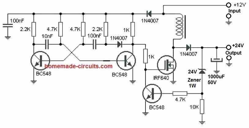
" rel="ugc">
Thank very much sir pls I’m doing micro generation of electrical energy that’s water will be held at a hide then allowed to flow through a pipe to fall on the blade of a small DC motor which will produce a DC voltage from 3_5v I now want to boost it up to a constant 12v using a switching regulator that will always read the input and output before switching since the output can vary from 5 to even 3.8v but it should supply a constant 12v and I intend to filter the voltage too sir ?
Yes, the circuit which I have referred to you will do exactly that.
This boost converter itself is a switching regulator, a boost converter switching regulator.
You just have to calculate the coil winding such that it gives a 12V output at 3V input, and then use a 12V zener diode at the output to stabilize this 12V.
In that case the MOSFET cannot be used at the output, instead you can try a TIP122 BJT
However, please remember that the output power (I * V) will be always sightly lower than the output power (I * V).
Thanks sir but the coil there I don’t know the specifications
Akafac, You will have to put some effort and calculate the inductor value depending on your output/input specifications.
In that linked article I have explained in detail how to calculate.
Can you do it?
No sir
Please provide the maximum output current requirement…
1A or lesser even sir
Pls sir, I’ll be glad to see your solving steps so that if I intend to change the current I can resolve for the inductor value sir thank
Akafac,
Please post your question with the all the details under the following post, I will explain the procedures in details to you:
https://www.homemade-circuits.com/how-to-generate-electricity-from-sea/
I use w1209 thermostats, cheap and very good for egg incubators etc. So cheap there are a lot of poor quality ones being made and sold. Thought I would get schematic and make Gerber file for getting these boards made. Three schematics for w1209 on internet and all incomplete. Many people would be interested in W1209 schematic as there are over 36000 videos on youtube alone, on setting and use. Hoping you might be interested in the schematics I have and making a complete one for everyone to see and use. Best regards
Thank you for the valuable information.
If you have the schematic, please send it to my email ID, I will make sure to update it under the relevant article:
My email ID:
homemadecircuits
@gmail.com
I am referencing two of your projects to see if there is a way to combine both to fit my needs.
the first project is the Twin or Split 12V Battery Charger Circuit with Auto-Changeover, this is a great design and it does work well, I have replaced the relay and driver transistor with this project SPDT Solid State DC Relay Circuit using MOSFET, in the original design, and although it works great I still have one issue to address which I am having a time getting figured out.
What I would like to do is to put some kind of delay to the circuit that would allow only one battery to be connected to the load until just before the other battery gets discharged. To clear this up Batt1 is fully charged and Batt2 is in the charging state, the way you have this setup is that when Batt2 gets fully charged it gets connected to the load while Batt1 is still in use, I get it that Batt2 would boost the load till Batt1 is discharged, realizing that the diodes will keep the batteries isolated. Is there a way to extend the delay to a point just before Batt1 is fully discharged, before Batt2 gets connected to the load. I would like to leave out any mechanical type of switching, possibly using the mosfet circuit above.
Thank you for all you do.
Thanks for this interesting questing.
Can you please post this question under the following article, I will try my best to solve it for you.
https://www.homemade-circuits.com/automatic-dual-battery-charger-with/
Hi, Swagatam,
I assembled On-delay circuit: " rel="ugc">
Everything works fine.
Question: Is it possible to have On-delay function and at the same time make Pin 3 oscillating instead of being constant “High” so I can connect LED to it and make it blinking?
Best regards,
Michael
Hi Michael,
That is not possible in that design.
Instead you can try any 555 astable flasher circuit, and just add a 100uF/25V capacitor between pin#5 and ground, that should do the trick to fulfill your requirement.
Will a flashing LED work?
It will work!
I have a question and the question is, is it okay to use a circuit breaker for AC power from inverter going to appliances, does it a little bit guard the inverter or does the magnet in the circuit breaker affect the inverter performance?
Using a circuit breaker for AC power from an inverter to appliances is perfectly fine and commonly done. It provides protection for both the inverter and the appliances in case of overloads or short circuits.
1. I want a circuit that will automatically allow dc 12v to flow off/on using LDR .
2. 1 want an automatic switch that will always turn on/off ac 110/220 using LDR.
You can explore the following page for more information:
https://www.homemade-circuits.com/how-to-make-light-activated-day-night/
Please, I want you to construct a circuit that can light up and charge a solar street light.
I am having difficulty in getting the main controller. Most of the lights I have are dead and no parts to fix them. I have sent you the picture of the solar street light for you to know the size of the solar light. It has 16 bulbs.
Looking forward to hearing from you soon.
Thanks.
Hello Elisius,
You must provide the complete technical specifications of the solar lamp LED, and also the street lamp. Just an image might not help!
Mr Swatagan , thank you so much for your prompt response.
The solar street light is a 200watts solar, Please ,I would like you to explain to me the more what you meant by technical specifications .
I sent the picture of the solar street light to your email address
. The picture might be of help for you to know the specifications.
Elisius, The picture does not have any information regarding the lamp voltage, current specification.
Please provide the voltage specification of the lamp module and the solar panel, and the functioning details of the controller.
Specifications for the solar street light.
*Input voltage: Dc 6v
*Power supply: Solar
*Light Source: LED
*Power: 200watts
*Solar panel: Mono crystalline silicon: 6v 75watts.
*LED light source SMD 3030 200pcs
*working Mode: Daylight control+Remote control+sensor
*working Temperature: -20-50
And what is the battery specifications?
Your LED module will require 200/6V = 33 amp current.
For this you may require a Li-Ion battery with a capacity of around 8V 325 Ah to last for 10 hours
For further discussions, please comment under the following article:
https://www.homemade-circuits.com/3-simple-automatic-street-light-circuits-explored/
a learner will always stress a teacher, now my question is how can we make a radio call or a walky talkies
For a walkie-talkie circuit, you can explore the following page:
https://www.homemade-circuits.com/?s=walkie+talkie
I want to make to make a small toy house for children to play with 5 foors, but I want to make a lifter using small DC motors found in old DVD players , please help design a the lifter circuit and technic movement design.
What should be the specifications of the movement?
the movement of lift or elevator should be up and down only for example when it leaves down to the second floor it stops for some small time then it continues to the third floor, until it reaches up, then it keeps coming back down while stopping stopping till it reaches down and it will begin going back up again thank you
Ok, I will try to figure it out soon, and let you know…
the movement should be from down to the up floors then down but I don’t know how you will even make the switches
So it will be a continuous up and down and up movement?
the movement should be if a switch is switched for it to go to the second floor it should move from down to the second floor and swagatam please let’s make it almost like a real lifter as long as the switches shall be outside and we shall not make a door for it
Making the movement like aa real lift is extremely difficult, because it will require a lot of coding and can be perhaps be done only through a microcontroller.
I saw a village solar street lights of 40w LED you had made, but please draw for me a design that will use a 7ah/12ah battery with a small solar panel like 10w or 20w solar panel with very good power saving, please draw it without automatic turn on, and the other please draw it with automatic turn on either with relay or without relay. Please make a design of LED either 40w LED or 30w led or below for that village solar street light
Hello Rashid,
Please post this question in the following article, i will try to solve your problem:
https://www.homemade-circuits.com/3-simple-automatic-street-light-circuits-explored/
Hello swagatam, I saw one of your post of making a solar charge controller of 10w solar panel and 7ah battery, so I wanted to confirm if I could use a 12ah battery and the controller would still work well, to be honest can a 12ah battery light 2w bulb or 4w bulb for 12 hours?
The second question is I’m requesting you to make a diagram for a 100w solar panel charge controller minus using a relay please that can charge 70ah battery?
Hello Rashid,
Please post this question in the following article, i will try to solve your problem:
https://www.homemade-circuits.com/3-simple-automatic-street-light-circuits-explored/
Good evening i am very new to Electronics but very willing to learn. i was bought a 3 candle garden light with each candle being powered by x3 AAA 1.5v batteries in series i believe. They currently have a wire from a positive to an LED and the a wire from the other wire to one side of a switch and the a wire with a resistor or some sort to the negative of the third battery.
i would love to be able to convert these to solar so I’m not replacing batteries every week. I sort of understand the circuit diagram but I’d like to make a circuit board with the relevant resistors, diodes and dark/light thingy. i can solder very basically so if given a diagram or better still a step by step diagram that would be great. i have 4.5v solar panels and 6v ones? I’d lime to use the battery holder it comes with which holds the batteries in series if possible? i can send you an email pic of the candle if that helps?
Good morning, and thanks for your question.
I think the first circuit from this article looks the most suitable for your application:
https://www.homemade-circuits.com/simplest-automatic-led-solar-light/
You can remove the shown LED and its series resistor and replace them with the wires of your LED candle.
If you have any further questions, please feel free to comment under the above garden light article, I will make sure you succeed with this project.
Hi sir, can you give me a diagram for charge controller for 24v lead acid battery using solar panel? This is my final requirement of my subject sir i badly need it :(.. thank youuu
Hi, Hughian,
Can you please tell me the Ah rating of the 24V battery, I will to provide you with a proper circuit…
hi sir, I got 15Ah rating here.
I got two 12v lead acid battery here I will connect them series to get 24v , because my prof said it need 24v and there is no available 24v in the online shop so I ordered two 12v instead.
Thanks Hughian, for the information, do you have any specific requirement in the charger design, like automatic cut-off, trickle charging etc.
Hi sir Swagatam,
I just want the circuit an indicator if the battery is fully charge an LED diode will light to indicate it is fully charge, I ill just use my multimeter to manually check the battery voltage if it is low then I will charge it again and LED diode will turn on if it is fully charge. thanks sir.. 🙂
Thanks Hughian,
You can try the following circuit:
" rel="ugc">
Please adjust the R2 to get 28V across the battery output points (without a battery connected)
Adjust the R4 preset so that the red LED just switches ON at this 29V.
Hi sir Swagatam,
Sir thank you for that diagram I have a question sir this transistor beside R3, is a NPN transistor? If it is NPN what model is that transistor? Thanks Sir
No problem Hughian,
You can use a BC547 for that transistor. It is a current limiting stage which will limit the output charging current to 1.5 amps suitable for the 15 Ah battery.
Hi sir Swagatam,
thank you very much sir, ill update you if it is working in my part. thanks <3
Thank you Hughian. all the best to you!
Hi sir Swagatam,
My classmate ordered 18V and 30 watts of solar panel, is it applicable to the circuit of the solar panel we ordered? Because the solar panel specs you provide is 35V. Thanks you very much.
Hi Hughian,
18V solar panel cannot charge a 24V battery, you will need a 35V 3 Amp solar panel for charging a 24V 15 Ah battery. 18V 30 watt panel can be used to charge a single 12V 15 Ah battery.
Hi sir Swagatam,
thank you sir for the reply. sir.
You are welcome Hughian….
Hi sir Swagatam,
Im back again 😅 , sir my teacher says it will be best if the charge controller is MPPT, and i honestly do not know what is that. If there is any to modify the circuit diagram you provide to me sir..
Regards,
Hughian
Hi Hughian,
I think your teacher would know better regarding the MPPT specifications and working which he/she wants you to implement, so you can ask your teacher to provide more information about it.
You can also consider trying the following design for the intended MPPT charging method:
https://drive.google.com/file/d/1oYdpFeBemVi_rT8oouiQjs7C_MdGLqjd/view
The previous circuit using LM338 cannot be modified for an MPPT charging.
Hi sir Swagatam,
Thank you very much sir.
Regards,
Hughian
You are welcome Hughian…
Hi Swagatam!
I have built the 15Amp voltage regulator as per the demo circuit given on p.19 here:
https://www.ti.com/lit/ds/symlink/lm338.pdf?ts=1729104861851&ref_url=https%253A%252F%252Fwww.ti.com%252Fproduct%252FLM338
I am assuming the LM358 opamp is to blame for it not working, because it is apparently not as sensitive as the offset input voltage of the LM307.
However, looking at the circuit above, I do not understand how it works. Why? Because the adjust pins of the two opamps with 2k Ohm do not get routed to the output of each regulator like they normally do. Do you think I should invest in a LM307 as per the diagram, or perhaps there is something I need to change in the circuit design?
Any insights would be most gratefully received.
Kind Regards,
Bhakti
Hi Bhakti,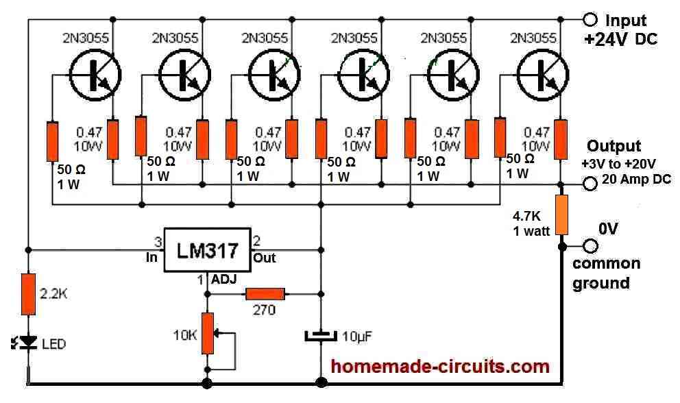
In that circuit the opamp is configured as a voltage regulator which senses the output and limits it as per the adjustment of the potentiometer. This information is sent to the base of the PNP emitter follower which adjusts the LM338 ADJ level accordingly.
Actually, there’s no need of the opamp stage, you can put all the LM338 directly in parallel and use them, as explained in the following article:
https://www.homemade-circuits.com/how-to-connect-lm338-ic-in-parallel-to-increase-output-current/
Alternatively you can build a 15 amp regulator using a single LM317 and a 50 amp power transistor, as shown in the following diagram:
" rel="ugc">
You can replace the 2N3055 transistors with a single: MJ11032
HI Swagatam!
Thank you for your prompt reply. Is it possible we are looking at two different circuits? The one I built has no PNP transistor but is the same one you documented here:
https://www.homemade-circuits.com/ic-lm338-application-circuits-explained/#15_Amp_Variable_Voltage_Regulator_Circuit
One reason for building it was an excuse to see how opamps work in different situations.
However, if I can not get this to work, I will just keep the 0.1Ohm 10w at the three LM338 output pins and cross my gingers that this “ballast” solution will work. It will be interesting whatever happens 🙂
Thank you Bhakti,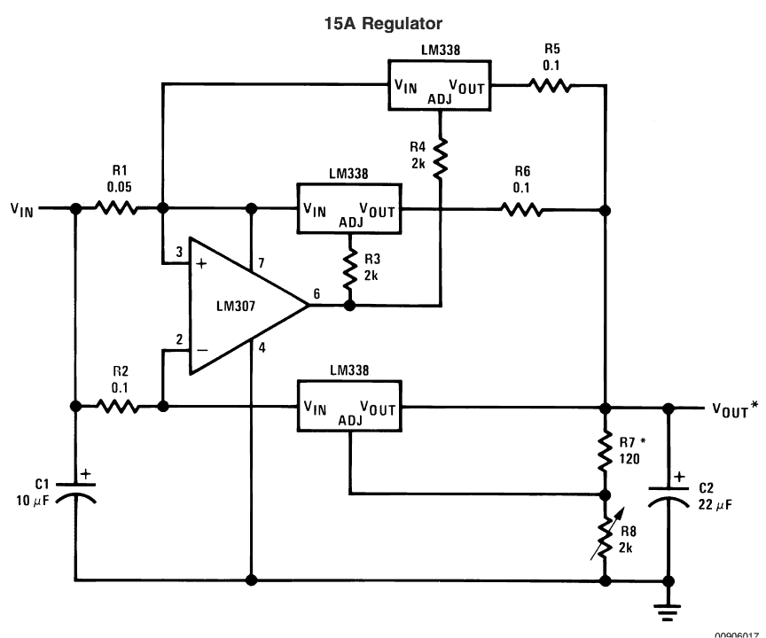
I may have mistakenly referred to another design of a 15A regulator which uses an op-amp and an PNP, in the datasheet.
In the following diagram which you have used, the op-amp is used as current sensor, when the current across R2 exceeds above the max capacity of the lower LM338 (5 amps), the opamp output goes low and activates the upper two LM338 ICs which provide the extra 10 amps to the load.
" rel="ugc">
The output resistors can be eliminated for the parallel LM338 ICs, if you mount all the ICs over a single common heatsink, very close to each other.
Hi,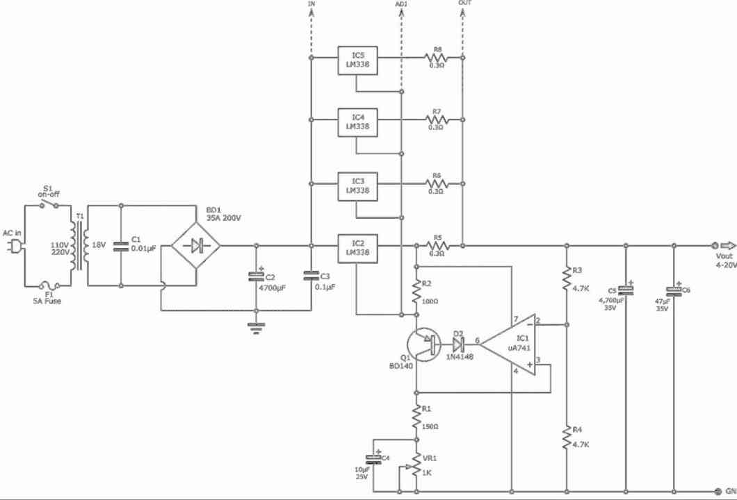
After I built this one with no PNP:
https://www.homemade-circuits.com/ic-lm338-application-circuits-explained/#15_Amp_Variable_Voltage_Regulator_Circuit
…I could not see it working. It is possible that I have not thrown enough current at it to make all three LM338s start to work. The LM338 configuration seems quite “unorthodox”. It does not involve the typical 240 Ohm between Adj and Out pin. I decided to experiment by isolating the behaviour of the LM338 with just a 2k Ohm between Adj pin and Gnd. And sure enough, with high resistance like 100k, the LM338 Vout was at a maximum, but when around 2k Ohm, it was just a couple of volts.
Not happy I was learning effectively about opamps, I saw this circuit which maybe similar or same as the one you first described:
" rel="ugc">
Well this interests me, because I can easily see how the opamp is sensing changes in the final Vout. My thought is that it increases the final Vout when there is a heavy load on the final Vout, so that the Vout voltage remains the same? But maybe it has more to do with the balancing of the numerous LM338 which are incorporated in this design? I also don’t see the need for a BD140 PNP when there seems to be maybe only 10mA going through it ( 1.25v / 100Ohm).
Hello Bhakti,
In the following circuit, the voltage across R2 must make the pin#2 of the opamp higher than pin#3 by 0.2V, only then the opamp output would go “LOW” and that would trigger ON the upper LM338 ICs. In short, the voltage
" rel="ugc">
You can calculate the minimum load current required for this using the following equation.
I = 0.2/R2
However, for this the pin#3 must be referenced at 0.2V also, which is not done??
Also, you are right, the ADJ pin of the upper LM338 must be coupled with the lower LM338 for the upper LM338 to correspond to the voltage levels set by the lower potentiometer, otherwise the circuit will not work correctly.
So it seems the above circuit has serious issues, not sure how this was included in the datasheet of the IC
The other circuit which you provided is correct, you can use try that.
Hi, I use w1209 thermostat in my egg incubators. Have purchased over thirty from very cheap to expensive, none work. Sending them back costs more that I paid for them in most cases. Have schematic, photos of both sides of PCB, but no gerber file to get some made by PDB makers. Is there anywhere I could find a geber file for w1209 PCB? Thank you for taking time to read this.
Hi, I understand the problem you are facing, however unfortunately upon checking I too could not find any online source that provides the PCB details for this project.
Greetings Swagatam,
I stumbled on your site while searching for diagrams for generating electricity from the Atmosphere. I currently have a simple small circuit with a few Capacitors and Diodes to generate 1.5VDC but the current is low and voltage is not sustainable with a small led. My main focus here is “Free Energy” as I use that term freely. I know you have posted many circuits and articles about similar subjects but I would like to build a working model that produces continues voltage with a small load. Over-Unity has also been talked about for some time now but it’s really hard to find diagrams of a true working model to build. So, if your able share a Project I could build at home that is sustainable I would love to try and build it to prove “Free Energy” is truly possible.
Thanks,
Sal
Hi Sal,
Have you tried one of the concepts from the following article?:
https://www.homemade-circuits.com/how-to-collect-free-energy-from/
Actually I haven’t tried these concepts practically, so confirming the results may not be possible for me at the moment.
However, I am aware that the key elements in these circuits are the antenna and the grounding (earthing) which must be perfectly done.
The antenna must be as long as feasible and totally isolated from the ground, while the ground or the earthing wire must be thoroughly inserted into the soil, as deep as feasible…
I want to make a motion activated rat trap using 12v power supply, a 12v pir and a linear pull solenoid. It needs to be basic as I know very little electronics. Can you draw a circuit please.
You must know the basics of electronics and how to solder, if not then you must first learn it and then I will provide you with the circuit diagram…
Hello teacher. I need your help. I need a basic electrical circuit diagram of a step-down convector DC-DC Step Down SKU 7915. Can you help?
Hi Valera, sorry I could not find any online information regarding the IC SKU 7915….
Alternator generator with a DC motor set up. While I am im the beginning brain storming phase, How would you stop it safely without causing injury to yourself of the device. In case I want a portable one for camping or leaving my house for several days.
Hi, sorry, I could not understand what type of safety measure are you referring to? Can you please elaborate.
Hello Teacher. I received your circuit diagram for L4975A. It indicates an input voltage of 35 volts. Should I first use a voltage divider to bring the 50 volts to 35 volts and then feed it to the microcircuit? Or can I immediately feed 50 volts to pin 9
Best regards, Valera
Valera, The L4975A IC’s maximum input voltage is 55V, so 50V can be used in the following circuit: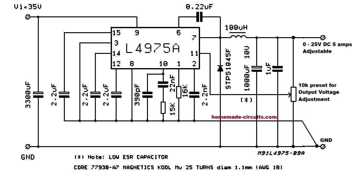
" rel="ugc">
I received your letter and the diagram. Where is the voltage divider or variable resistance instead of the divider? And one more question – how to determine the internal resistance of a diode floodlight
The 10k preset in the previous diagram is the feedback resistive divider.
Sorry, I am not sure how to determine the internal resistance of a diode floodlight.
Hello Teacher. I purchased L4975A and as you promised I will try to provide a circuit diagram for 4975 with feedback, to obtain a stabilized voltage of 17 volts with a load of 3 amperes. The load is a spotlight and it is desirable to take into account the power dissipation of the microassembly
Hello Valera, you can try the following circuit:
" rel="ugc">
sir
I am from Thane ghodbunder road,
wish to visit you.
please if possible spare few minutes for me!!
Hello Bhupendra, Do you have any circuit related question? In that case you can feel free to communicate with me through this commenting platform, I will try my best to solve it for you. Please let me know!
As a model railroader, I have a crossing gate that needs to stay activated through a six-foot zone, and stays activated as long as a train remains in the zone. Could I use a six-foot piece of metal track or maybe a copper wire as a sensor plate with one of the circuits described in this article? Cars are mostly plastic.
Thanks for your question, could you please specify which circuit diagram you are referring to? I will try to figure it out for you…
hello sir,
fi am working on lvdt project.i am using peltron lvdt for measurement .As per the datasheet power supply is 3.6 vrms at 3KHZ and the output is +- 1.2v rms . my requirement is precious 3.6vrms at 3khz generator circuit and for the output i require precious rms to dc convertor circuit. Pls. suggest circuit for this project. thank you.
Hello Sridhar,
You can try any of the transistorized version from the following article, and adjust the relevant RC components for getting the desired effects.
Since your input is 3.6V, only transistorized circuits may be suitable.
https://www.homemade-circuits.com/simple-sine-wave-generator-circuits/
I constructed inverter circuit using irf9540 & irf540, it works perfectly with 12volts transformer. I need to use 24volts or 48volts transformer with the same circuit. What should I do. Thanks indeed.
If you are using P-channel MOSFETs in your H-bridge design, then I am afraid you cannot use a load voltage higher than the Vcc supply voltage of your oscillator IC, unless perhaps you use a boost converter at the oscillator outputs.
Hi Swagatam, I saw your article about a wireless charger (Wireless Charger) and I thought it was great and perfect for my university project. I was wondering about the gauge of the 2 core speaker wire used for the Transmitter and also the gauge for the Receiver.
Thank you Robert,
Sure, you can use it for your university project.
For the transmitter you can use any standard two-core flexible wire as shown in the following image:
" rel="ugc">
For the receiver the wire can be a 0.5mm super enameled copper wire.
Please let me know if you have any further questions.
Thanks for the immediate response! Ideally, how many turns should the Receiver coil be? And what should its ideal diameter be?
Actually the receiver coil can be exactly identical to the transmitter coil, however you can experiment with it to get the most optimal results. It might require some experimentation until the right number of turns and diameter is achieved.
It must be noted that the current output from the receiver coil can be significantly lower than the input current to the transmitter coil, and will be directly proportional to the distance between the Tx and Rx coils.
If the current from the receiver coil is not sufficient, the mobile phone might not charge properly.
Make sure the current to the transmitter coil is at least 3 amp, @12V
Hi, your circuit works like a charm! Right now the only problem that I have is that the out is fluctuating. What can I do to stabilize the Voltage and current output of the receiver coil?
That’s great, glad it is working.
To stabilize the output, please connect a 2200uF/25V capacitor right across the output terminals of the 7805 IC.
Would it be possible for you to send a 10 second video clip of the result to my above emails?… if not, no worries.
Sure! I’ll send the video through your email.
Ok, thanks so much…
Can you recommend an inexpensive place to have circuit boards made? Not for a production run, just one at a time. Thank you!
For the single PCBs the cost can be immensely high, no matter which supplier you choose.
Instead of a PCB I would suggest you to build the prototype over a strip-board.
It has been a while since I etched a circuit board, but I think I still can. It will be much cheaper than having one made. Thank You!
You are right, etching a PCB yourself can be much cheaper and interesting also.
Hello Swagatam, I recently bought a stabilizer Model: URZ3412 – 1000 VA
Input: Voltage range 145-260 VAC
I live in the UK and I need 230-235v. The problem is the stabilizer is set to 260V. It has internal settings but I don’t have its diagram. How can you help me. Thank you. N.C.
Hi Niki,
Unfortunately without a schematic it can be impossible to know which preset setting must be tweaked to adjust the high voltage trip level. Randomly testing the presets can be dangerous, so a schematic is necessary.
Hi Swagatam,
Looking for a circuit that opens a door (motor positive direction), then, upon reaching a limit switch, reverses (motor negative direction) to close again (limit switch ends the cycle). Just using a one-button, start process. Liken this to a garage door that closes immediately after opening WITHOUT the need to press CLOSE/OPEN again.
Hi David, i have an easy circuit design in mind, i will try to post it as a new article, and let you know soon…
I have designed the required circuit, you can find it in the following link:
https://www.homemade-circuits.com/automatic-door-controller-circuit-using-a-single-push-button/
Excellent work! Will begin construction. And extra thanks for the prompt response.
Sure, no problem! All the best to you.
Let me know how it goes.
I have a wireless reversing camera (AutoVox TD2) fitted to my car which switches on the screen when I engage reverse gear (power from reverse light connection). It functions perfectly with one exception, when I disengage reverse gear the screen switches off, ie the camera has no more power to it. Is there a way to maintain the power (12v) running to the camera for 10-20 seconds, as I manoeuvre the car, as in parking?
Please try the following circuit, it will fix the issue instantly:
" rel="ugc">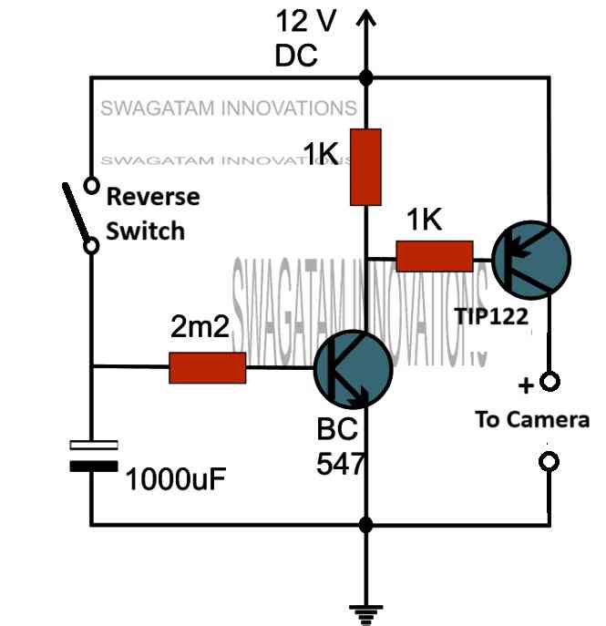
The delay OFF time can be tweaked by adjusting the values of the 2.2M resistor or the 1000uF capacitor, or both.
Thank you for your prompt reply!
You are welcome. Let me know if you need any further help…
Very kind of you, thanks again!
Can I connect this circuit by joining the wires in parallel, is there a need for any diodes to prevent current reversing if I do ?
For the +/- supply connections, you can add a 1N5402 diode in series with the positive (+) supply line to safeguard against an accidental reversal of the supply polarity.
For the output from the TIP127 there’s no need to add a diode, since the camera device would be having an internal diode with its own circuit.
Please note that the pnp transistor is mistakenly shown as TIP122, it should be actually a TIP127.
Hello Swagatam,
I am interested in your project Mobile Phone Controlled Robot Car Using DTMF Module. I need to buy it. Can you give me details to purchase it.
Thank You Chaitanya,
I understand your requirement. However, I do not build or sell readymade kits nowadays, so selling the unit may not be possible for me.
Hi ,
By reading all the comments, i am overwelmed to see a mosquito window powered by electricity. I am not a technical guy to build it but looking for such products to purchase.
My colony has high presence of mosquitos and every now and then someone is getting sick.
Hence a sincere request to buid the mosquito window. I am willing to bear all expenses related to the creation and installation of such window. However, if similar products are already available in the market, I would appreciate it if you could share any relevant links or information to purchase them.
Thank you for considering my request. I look forward to hearing from you soon.
Hi, I am glad you found the post helpful.
I can understand your problem and i wish somebody could help you in this regard.
Let’s hope someone on this forum listens to your request and builds this project for you.
By the way, if you search amazon you should be able to get such products ready-made also.
Hello Swagatam,
I’m interested in understanding how an MPPT really works.
I’ve studied the circuit https://www.homemade-circuits.com/mppt-circuit-using-lm317-ic/
but I cannot detect the part that is making up the PWM in this circuit.
As the LM317 is a linear circuit, that cannot, in my opinion, be part of PWM and will produce a lot of heat.
Can you please destroy my doubts about this part !
Thanks Wolfgang
Hello Wolfgang,
Actually in this concept the LM317 is configured as a switching regulator. Here’s what the datasheet of the LM317 says about this configuration:
Low cost adjustable switching regulators can be made using an LM317 as the control element. The figure shows the simplest configuration. A power PNP is used as the switch driving an L-C filter. Positive feedback for hysteresis is applied to the LM317 through R6. When the PNP switches, a small square wave is generated across R5. This is level shifted and applied to the adjustment terminal of the regulator by R4 and C2, causing it to switch ON or OFF. Negative feedback is taken from the output through R3, making the circuit oscillate. Capacitor C3 acts as a speed-up, increasing switching speed, while R2 limits the peak drive current to Q1. Efficiency for the regulators ranges from 65% to 85%, depending on output voltage. At low output voltages, fixed power losses are a greater percentage of the total output power so efficiency is lowest. Operating frequency is about30 kHz and ripple is about 150 mV, depending upon input voltage. Load regulation is about 50 mV and line regulation about 1% for a 10V input change.
I am curious if you are interested in build/code/test and selling some relatively simple prototype devices PC/arduino (or other such devices – we use PSoC LP5 a lot, but whatever you prefer) prototype devices, for example the timed temperature programmer you described (https://www.homemade-circuits.com/programmable-sequential-temperature/#comments), I will use them some chemical instrumentation research that I do – I used to do this myself but I havent kept up and my students have learned chemistry, its an uphill struggle with a soldering iron or coding. Let me know… (you can get my website by googling my name)
Hello Purnendu,
I appreciate your interest in this field, and I really wish I could help you, however building and testing a prototype practically may not be possible for me at this moment.
I googled your name on internet and found interesting details about you on Wikipedia and other sources.
Thank you so much for commenting in this blog. Please keep up the good work.
Hello, trying to replicate a neon bulb that flickers like a flame. I repair vintage clocks and the click in question has a neon bulb with a 220k resistor that us supposed to simulate a dancing flame. I trued using some new neon bulbs with a new 220k on one leg and I get a steady glow. What am I missing? Do I need a special bulb or? Thanx in advance Greg.
Hi, Please do the connections as shown in the following diagram, it should work: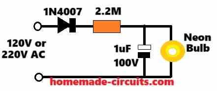
" rel="ugc">
I am planning to use a 220 volt induction heater probably 15 kw or 25kw.
I plan to use the induction heater in an unusual way.
I want to use it to heat pipes filled with different chemicals. The pipes will be sealed and heated to approximately 400 f. This will significantly increase the reaction of these chemicals. These chemicals need to cool down before I can remove them from the pipe.
My idea is to heat one pipe at a time. When the proper temperature is reached, I will turn off the electricity to that coil. Then I will turn on the electricity to the next coil in the line.
In the meantime the pipes that have already been heated will have time to cool.
I am not sure how to wire this. I know you can purchase stove top induction cookers with four different burners. I assume all four burners can operate at the same time. Also, they can operate with just one or two burners.
Can this work by going through a series of relays?
I would very much appreciate any advice that you may be able to offer me.
Thank you very much for your help.
I think you can turn ON/OFF the induction heater units through separate SPST switches, a relay is not necessary. The setup can be something similar to the following design. You can add individual ON/OFF switches in series with the supply line of the respective induction heater units.
https://www.homemade-circuits.com/tap-water-induction-heater-circuit/
Topic: Extending the working high voltage limit of a ready-made SMPS.
Low-power conventional SMPS (2A/24V for example) are rated to work between 100 to 240V. Is there a posted circuit which could be added externally to extend their working high limit to 380V?
Please note that I don’t mean just protecting them from a high voltage (by disconnecting them for example).
Thank you.
Hello Kerim,
The working high limit of an SMPS is around 285V RMS that is equal to 285 x 1.41 = 401V
Thank you for your prompt reply.
You likely refer to SMPS units which are different from what our local retailers have (imported from China). At best, they may work up to 260Vrms before they burned.
It seems that your 401V is a peak voltage. I meant by 380V the 2-phase voltage (Vpeak = 537 V)
Ok, but that looks very high, I do not have any circuit at the moment with me , which can control a massive 537v for the smps, a linear regulator can be used but that might heat up a lot.
The input current of such SMPS is relatively small. So, a hi-voltage MOSFET (with a diode bridge) could be made to act like an active hi-voltage zener (about 200V when on). It will be connected in series with the SMPS. It is shorted (actually its lowest voltage drop is a bit above its Vgs threshold) when the mains voltage is below a certain limit (for example, when the instantaneous voltage <300 V, peak of 212 Vrms). And it turns on above it (sine tips). An opto-coupler will likely be needed to isolate it from the mains level sensor which drives its gate.
Yes, that’s right, since the current is relatively small a mosfet regulator might work in a source follower manner.
An isolation might not be required according to me.
https://www.homemade-circuits.com/0-300v-variable-voltage-current/
I wish that isolation is not required.
If I understood you well, the mains instantaneous voltage sensor (to drive the MOSFET gate) and the source pin of the MOSFET can have the same reference node. I personally can’t see how this could be done.
I am actually referring to the following circuit: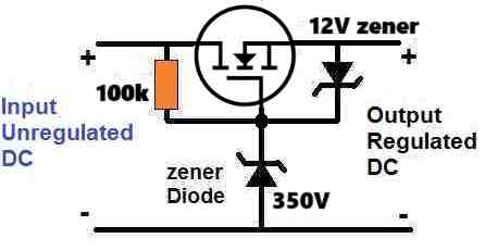
" rel="ugc">
Now your solution is crystal clear, Thank you.
I will try to simulate it.
Sure, no problem.
I simulated it. Then I built it to test it with 24V/1A SMPS.
I did it because I was worried about the new lowest voltage limit. Usually, it is 90Vac at full load. First, I tested with a load of 8 // 220R/5W (about 873 mA). The lowest voltage became 115Vac. But it decreases to 110Vac with 6 // 220R/5W (about 655 mA). Finally, by adding 2uF/400Vac at the regulated output, the lowest voltage decreases from 110V to 100Vac. This result seems suitable for my application.
Thank you again for your help.
OK, great, thanks for updating the information. Appreciate it.
It seems I can’t receive notification emails from you (in the inbox or spam folder).
I wonder if you may have an idea on how this could happen.
Thank you.
Sorry, I don’tknow how to solve this, because if I am able to get the test notification then you should be also able to get it. You can perhaps try commenting with a gmail or an Outlook account and check if that works.
It may be a silly question. Should the ‘bell’ button (at the left of ‘POST COMMENT’) be pressed or not to get back an email (I mean for other readers).
What confuses me is that its pop-up text is the same after pressing it.
Usually, the pop-up message tells what will happen if the button will be pressed. And after pressing it, its message reverses too.
The bell button by default is enabled to notify the entered email IDs. If you press it and if you see a cross mark on the icon, that means the notification is disabled.
I just read your reply on the other page (4046).
It seems it is out of our control to let your notification emails reach my inbox. So, I will try to visit your pages, once a while, on which you may reply.
Sure, no problem.
Sometime back, I had posted a question regarding countdown timer with display. You had kindly replied and I had added my response etc. I would like to find this thread again.Can you please help?
Thanks and best wishes!
Hello Dr. KV,
I think it is in the following post, please check it out.
https://www.homemade-circuits.com/best-ic-4060-circuits-and-projects/
Sir, I need some assistance in stimulating a circuit which is ground fault circuit interrupter (GFCI). RV4145 is one of the GFCI’s. I faced problems while simulating a part of leakage current detection. Basically I want to simulate a current transformer (CT). It will detect leakage current of 5mA. The turn ratio is 1:1000. CT primary is line and neutral of the power supply. During normal condition, the CT won’t operate as the line and neutral will cancel out the current. During fault, 5mA current will flow and is sensed by CT. Its secondary will step down the leakage current by factor of 1000. Then there is an IC (RV4145) which has 8 pins. 1. Feedback, 2. NC, 3. V Reference(13 v), 4 Ground, 5. SCR trigger (signal is sent to scr which will trip the relay), 6. +vs (26) here, 7. Op amp output, 8. NC
CT secondary is connected to pin 1 and 3.
What i did is I connected a sinosoidal current source of 5mA tp primary of CT. Then sets coupling factor to 0.001 in proteus which gives 5 uA in secondary. The secondary is then connected to op amp which gives voltage output (which forms op amp output at pin 7). Then two comparators are connected which is regulated by 4 zeners (6.2 V each), and it creates v reference at pin 3.
Please sir can you please provide assistance in solving this. Im new in this and i can’t figure out how to solve this.
Hi Zoya, thanks for asking this question, I understand you want to solve a circuit simulation problem, however since I do not use softwares to simulate my circuits, my knowledge of circuit simulation is not good, so I am sorry i won’t be able to help you in this regards. I hope someone else on this forum is able to solve this for you.
Thank you for the reply. Can you please tell me where i can find such forums. I new in this and i really need some guidance. I hope you understand this. I actually want to use in proteus, where line and neutral will be the primary of CT, and the secondary will give current differential. Please help me in this. My question is similar to this project of your.
https://www.homemade-circuits.com/load-current-control-through-current-sensing-transformer/
I understand your problem, however my knowledge regarding proteus simulation is not good, so I cannot solve it for you. Did you try searching for “proteus related forums” online? Please give it a try.
Sir, I need a simple circuit to detect the flow of water and if there’s no water flow (with time delay) then there should be a buzzer alaram. As I already have a water level controller I wish to connect this to the power supply which is connected to the motor.
With regards
Gargi.?
Hello Suresh, you can try the following concept: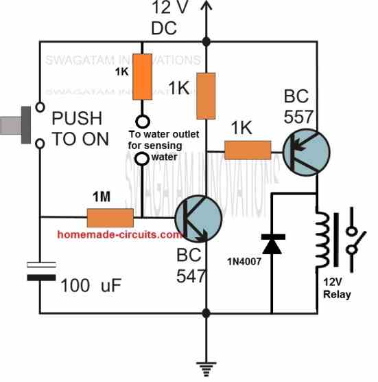
" rel="ugc">
Hello Swagatam to both you and your”gang” or team. I’m a highly ki accomplished technician with thorough exp in almost all consumer electronics eqp right from valve,s. But my strength is in analogue and not digital.As I’ve executed many projects for many ppl, I have a core issue in ex a control unit for a small domestic luggage lift that has to be installed in a building of 5 floors. The only issue here is getting the lift to anyone who summons it. The lift should have floor buttons in order to send it to its desired”destination. Ideally the should be only a call button which will summon the lift. “The whole operation of proposed to be hauled by a winch, appropriate counter weights, door alarm, overweight activator, intercom B/w car and desired destination, and everything else which has been already worked out.I need serious assistance in this particular aspect and I will def tell you how it’s panning out. Thought assistance in this cnnx will be deeply appreciated. Thank You Very Much.
Thank you Prasanth, for this interesting question.
What you are asking is actually a full fledged lift operating circuit which might involve relatively complex digital circuit configurations.
Actually I had tried to design a lift circuit before but failed to do it.
If possible I will give it a try, if I succeed I will surely let you know..
Fantastic
It Is 24 V to 400V ( 0-1Amp )
You can try the first circuit from the following article:
https://www.homemade-circuits.com/12v-car-laptop-charger-circuit-using/
It is a CV circuit but not CC. For CC you will have to add additional stages.
You will have to use a 400V zener diode and adjust the inductor coil to get above 400V.
I am in need of designing of 12 V to 24 to 400v ( 1 map ) Boost converter variable CVCC type of supply pls help
Hello,swagatam I want to discuss about 12 volt solar pan type induction . Should I get your cell number ? Thank you.
Hello Shabbir,
You can feel free to discuss it here through comments, if possible I will try to solve it for you.
Hello Swagatam! Happy New Year!
Swagatam, I have long wanted to create a neurostimulation device and I am tormented by the fact that I do not have enough knowledge and experience to create a circuit diagram of my device.
I want to create a TRNS (transcranial random noise stimulator). It uses an alternating current of random frequency (from the range of 100-640 Hz) and random amplitude (from the desired range of -1.5 to 1.5 mA). How to force the current to take this form?
tRNS stimulation differs from tDCS in that instead of constant direct current delivery, current levels are randomly generated, with a Gaussian distribution around a specific mean intensity. Other parameters related to the stimulation electrodes, like position and size, are similar to tDCS.
Do you know what a schematic diagram of such a device might look like?
Thank you Nikita, and a Happy New Year to you too!
I think I may be able to design this circuit.
So it should be basically a randomly varying current source (AC) with a randomly varying frequency, right?
And the voltage range can be anywhere between 10V and 60V, I guess.
Let me know your thoughts on this?
I would really like to share my thoughts on this matter if only I had them. I have much less knowledge and understanding on this issue than you. Therefore, it would be better to entrust this to you.
Probably the most useful thing I can do here is to send links to sites that have information about trns.
 ?fit=753%2C499&ssl=1 (this shows what the current shape should be)
https://en.wikipedia.org/wiki/Transcranial_random_noise_stimulation
https://brainbox-neuro.com/techniques/trns
" rel="nofollow ugc">
?fit=753%2C499&ssl=1" rel="nofollow ugc">
I am new to electronics and planned to create this device in the future when I mastered electronics well enough.
Ok, got it, thanks very much, I will look into those articles for the related specifications and try to figure out an appropriate design for the project.
I will publish the design as a new post, I will notify you once it is done?
Of course, thank you very much!
Hello Nikita,
I have published the post, you can find it in the following link:
https://www.homemade-circuits.com/transcranial-random-noise-stimulation-trns-circuit/
I need help with a circuit controller. It would help if I could upload a diagram to explain how I want the lights to function, but I will try to explain. This is for 12V DC, 9 LED lights (these are small LEDs, sort of like a side marker light, I do not know the amperage draw). I need an easy to program controller, something like all I have to do is make simple delay/time changes (I am not a programmer), and something I can seal from the weather, and not be bulky for mounting.
There a 9 LED lights, they are to be mounted horizontally (from left to right 1-9). The controller needs to control the lights as such:
All on at max brightness (this would be the start of the cycle), if at start all are at max brightness then they would all need to have their brightness reduced to say 50% ish, Light 1 would increase to max brightness then decreases to say 50% brightness as Light 2 increases to max brightness, then decreases as Light 3 increases and so forth.
After a cycle or two of progressive increase/decrease across all lights (at the end of Light 9), all lights will go to max brightness for a short cycle (like 5 seconds) and then enter the progressive increase/decrease phase. This is a continuous loop. Hopefully you get the idea
Basically, I want the LEDs to give a wave affect.
Your help is appreciated
Thanks for posting your circuit requirement! I will design it and post it in a new article. I will let you know once it is done.
I have tried to design the circuit, you can find it in the following link
https://www.homemade-circuits.com/led-light-wave-effect-generator-circuit/
Thank you very much for the circuit and quick turn-around. Once I get it built, I will let you know.
You are welcome. All the best to you!
Thanx for all these wonderful circuits. Recently my dryer motor burned due to overloading and even fuse cannot save it. The motor is 40W, 220v. B4 buying a new motor, I intend to do some research to have some circuit in series with motor itself so it can detect overload and disconnect it. Please let me of any effective circuit probably with some adjusting customization to fine tune it with motor specs. Thanks and regards
Thank you Sak, You can refer to the last circuit from the following article. You will require a relay control or an triac control to auto cut off the motor when over current is detected:
https://www.homemade-circuits.com/dc-motor-protector-circuit-over-voltage/
I want circuit for break of motor.
In put: 200 VAC, 2 Phase
Out put : 110VDC
Break voltage 110 VDC, 2A
Sorry, I did not understand what you mean by break voltage?
Hi! I m from Turkey.
I need a schematic to control two relays with timer. I saw some schematics at this page. But i couldnt use them. They have some differences. Would you please help me.
The timer has 2 adjust. Toff and Ton.
When I turn on circuit it waits as t-off time. Then relay 1 is on as t-on time. Later r1 is off and waits again t-off time. After that relay2 is on during t-on time….it runs till I switch off.
T off 0-3 minutes
T on 1-5 minutes
…..
Turn on
1 min wait
3 min run R1
1 min wait
3 min run R2
1min wait
………..cycle
Turn off
Hi, I have designed the circuit for you. You can find it in the following link. Make sure to adjust the 100K pot to get 1 minute ON/OFF duty cycle from the IC 555. I think you may have to use a 1M pot instead of 100K for getting 1 minute ON OFF duty cycle.
" rel="ugc">
Hi Swagatam I have a Texas Instruments processor that initializes a ULN2003A to switch a GND signal to an opto isolator which already has 12v present which switches a SMPS on . the problem is that according the circuit the processor should send a high/positive signal to the ULN2003A but it sends a GND signal when measured at an input of the ULN2003A relative to the 12v on the opto isolator, As the ULN21003A needs a positive input to initiate a GND output via open collector output.
How can I generate a high/positive signal for the ULN2003A input from the low/GND input of the processor..
BTW there is a brief 1.1V odd measured at the input of the ULN2003A at power on , then the input pulls low or to GND
Hi Andrew, I think the following design will do the job for you.:
" rel="ugc">
Please ignore the relay and the diode, you can simply use the collector of the transistor to acquire the positive signal in response to a negative or ground signal from the processor at the base (trigger input).
Hi, This is regarding Piano, Guitar Sound Effect Generator Circuit. I would like to understand what exactly the input given to start button. Does it accepts External Audio signal from a Musical instrument from its Piezo Pickup. So that i can get a sound of say Piano, Flute from the Audio signal given from my string instrument like Guitar or Mandolin ? Will it capture and deliver the exact pitch of a musical note as a piano or flute sound given from input Audio signal?
Hi, that circuit is a sound effect generator, it is designed to generate a special note resembling guitar or piano by its own, as per the settings, and in response to the pressing of the start button. It is not designed to accept external frequency inputs.
Thanks for Clarification. Do you have any solution for my requirement. I have seen such a device developed by Roland ( GR-55 Guitar Synthesizer). I know it may be very difficult to develop. I will be happy if i get only violin and flute tone. I intend to use a foot switch to trigger.
Yes, it can be indeed very difficult to design an identical circuit, however I have a guitar amplifier circuit which will accept external signals and amplify it accordingly….I would recommend the second design from this post:
https://www.homemade-circuits.com/100-watt-guitar-amplifier-circuit/
Hi, we have problem of stray dogs in our society and it is getting worse day by day. can I get some ultrasonic dog repellent circuits to reduce the problem? Do these ultrasonic sound dog repellent really work? what is its working range? If I can get some tried and tested solution it will be a great help.
Hi, you can try the second last design from the following article, it is a tested design:
https://www.homemade-circuits.com/dog-barking-preventer-circuit/
Hi,
I’m interested in controling the BP of a 10 gallon pot of beer. I have a hot plate 220v 25A that is manually controlled. I thought at first to use PWM through an opto isolator to a 30A triac. This may be ok but would I be better off trying to use phase angle control like a light dimmer? The on time allowed to be altered by the R adjust; effectively PW modulation. I don’t have clear idea on the best approach.
The triac considered is T3035H. I started off committed to PWM but prior to actually implementing same it occurred to me that I should be treating this as triac’s were intended.
Do you have any suggestions?
Thanks,
Keith
Hi, both the techniques are good and will allow you achieve the goal, however the light dimmer method can be much easier to build and implement. Please let me know if you further queries.
Hello,
I am working on designing a led strip which must operate in the following manner:
Blink—> Blink—>Blink—>Fade ON.
Is there any possible way to achieve this without using any microcontroller IC?
Please help me out !!
Thank you in advance.
Hello,
It may be possible in the following manner, ON-OFF-ON-OFF-ON-OFF-Fade ON.
Could you kindly help me make the circuit. As of now, I have two separate circuits:
1. Blink circuit, using 555 timer.
2. Fade ON part using transistors
But I have no clue how to cascade both the circuits to operate in Blink–>Blink–>Blink—> Fade On.
If there is any other way, I would humbly request you to kindly guide me.
The Blinking effect proposed by you can be interpreted as ON-OFF, ON-OFF, ON-OFF, then Fade ON. This may be difficult to achieve using your two circuits, however it may be possible using an IC 4017 and IC 555 together.
If the above effect looks OK to you then I can provide you with the circuit idea.
Thank you so much for your insights. If you don’t mind, could you kindly help me make the circuit? I would be very grateful.
No problem, I will try to create the circuit, can you please tell me what do you want to illuminate, I hope it is LEDs. If it is LEDs please provide the specifications of the LEDs, quantity, voltage, current etc.
Thank you so much for your support. Yes, I want to illuminate LEDs.
total number of LEDs: 29
Voltage: 2V
Current: 25mA
Kindly let me know if you need any further information.
No problem, you can try the following concept. Make sure to use proper resistors with the LEDs:
" rel="ugc">
Thank you so much. I am very grateful. I will definitely try this circuit out.
You are most welcome, let me know if you have any further questions.
hello brother, I am an electronic repairer not a programmer, please I need some information from your experience. in this diagram of Arduino 3 phase inverter circuit, my question is that I can change the MOSFETs with a smart power module (FSBS15CH60) because I have many treadmill motor controller boards which have an error on the microcontroller?
tanks
Hello Nassih, I checked the datasheet of the FSBS15CH60 and from its internal schematic it seems the module can be used as the inverter output stage in place of individual mosfets. However, the pinouts of the module will need to be replaced correctly otherwise there can be serious problems.
Hi Swagatam,
I would like to control an 8-channel 12V Relay Module with a normal pulse switch to use on my vehicle. When I checked the parameters the IN1 to IN8 does not have any input specficiation. On some websites, 0 to 1.2 volts but polarity is not mentioned. My source voltage is from 12 to 14.2v max @ vehicle running condition. Product link below mentioned
" rel="ugc">
" rel="ugc">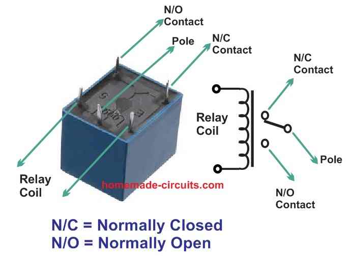
Hi Anuraj,
The relay you are referring to is a 12V DC relay, since this value is printed on the relays.
Design#3: DC Motor Controller with Multiple Features
https://www.homemade-circuits.com/dc-motor-speed-controller-circuits/
hi sir i have small clarification required on this relay you given in this (12V/5A) dual channel its looks like two pole contact, please explain me little more about this section.
Hi Pradeep,
It is a DPDT relay. The upper contacts shown in circles are N/O and N/C pairs of contacts. The switch action is shown by the pair of moving contacts of the relay connected to the lower circle which forms the common pole of the relay. When the relay is powered the movable pair of contacts connect with the pair of N/O contacts, and when the relay coil is not powered the movable pair of contacts connect with the N/C pair of contacts.
In the circuit this relay is used to execute the reverse/forward rotations of the motor.
I read your excellent article about heating element control with triac.
I would like to make a control of a 230V ceramic heating element (5-10watt) with a BT136S 600D triac and an ATtiny as a pulse generator. How do I calculate the pulses so that I can change from 65C to 80C in four steps?
I’m thinking of controlling it a with a push button and some LEDs for indicating temperature. Can you help?
Thank you Flemming,
Can you please show me the link of the article so that I can check it out for the details?
Sorry late reply, I’ve been down with corona, but are fine now. I just searched, heat and triac, and read what was there…. So I thought I maybe could reach out to you for help. I only know a little about electronic circuits.
What is the input voltage like, is it AC 220V or 120V? If yes, then I would recommend you an ordinary triac based light dimmer circuit as explained here:
https://www.homemade-circuits.com/how-to-make-simplest-triac-flasher/
I’m wondering about a delay on, then delay off circuit, with no button, 5v DC. I have a usb port, I would like to power on a linear actuator ~5 seconds after the USB port supplies power to my circuit, then turn it back off after ~0.5 seconds and remain off until the USB port is powered down, then repeat the cycle when the USB port is powered on again.
You will require a two stage programmable timer circuit for this application, as explained in the following article:
https://www.homemade-circuits.com/how-to-make-simple-programmable-timer/
Good afternoon!
I’m a complete amateur, who took a micro-electronics class in high school. I now have a deaf son that has recently started school. He has a tendency to make a lot of noise because he can’t hear himself and he can be a disruption to the rest of his class. I would like to make a noise visualizer, that would allow him to self correct because he can see when he is making noise. I came across this post (https://www.homemade-circuits.com/simple-audio-spectrum-analyzer-circuit/) and it seems like this might be what I need for this application, but want to confirm that there is a chance this will work for what I need before I invest too much time or resources into building this project. Does it sound like this is the correct circuit for an application like this? Thank you!
Hello Tom,
I would rather recommend you the following circuit which is a tested design and looks more relevant to your requirement. Hope it does the job for you.
https://www.homemade-circuits.com/wireless-music-level-indicator/
Hi Sir,
I am given a project to design a Printed Circuit Board (PCB) for a power factor correction circuit for a single-phase load using all required power and electronic components. Can you please give me a circuit for this design and ideas to proceed further.
Thank You
Hi Tashi,
Sorry I do not have a PFC circuit with me right now, however I think you can find some important information in the following article:
https://www.onsemi.com/pub/Collateral/HBD853-D.pdf
Hi looking for large motor activated by an phone
Hi, you can refer to the following post:
https://www.homemade-circuits.com/gsm-pump-motor-controller-circuit-using/
Hi there mr. Swagatam, I want to convert a 2-0 volt signal to a 4-20mA current signal, the sensor needs 5VDC power and the output signal should be 24VDC. I’d need to flip the signal and convert it. what would be the best way of doing this?
I was thinking of using 2 non inverting opamps, one as a buffer and the other to increase the span of the signal, maybe 0-10V. My issue is just to convert the voltage signal to a reliable 4-20mA signal.
What do you think is the best voltage to current conversion circuit?
Hello Gerhard, are you trying to convert a 2 V into 24 V (4 – 20 mA) signal? What is the current capacity for the 2 V signal?
Hi again,
About 998EX sensor and delay circuit, I forgot to mention that I need this delay circuit to be simple and if possible with npn transistors or N mosfet.
I am very grateful for the content of your website, and I have refreshed my knowledge with the explanations that you offer of each published circuit. My best regards for the great work you do in favor of the world of electronics.
Thank you so much.
Hello Sir, i need help with a delay circuit,
I want to use an ADEMCO 998EX infrared movement sensor so that when it detects movement it activates a relay for a period of 3 to 5 min. This sensor works as follows: it has two output terminals to notify the detection. This output is normally open when the sensor is not connected to power, and when the sensor is powered with 12v, it takes 1 minute to balance the temperature it senses in the place (during that minute the output remains open) and then, it changes to activated waiting for an infrared movement (in this state the output changes to closed and showing 1kohms between its two output terminals). When the sensor detects any infrared movement, the output changes to open for 2 seconds, and returns to closed waiting for another movement detection. Internally, the sensor has a SPARTAN SIP REED NormallyOpen relay (COTO 9007 series 4 terminals) with a resistance of 15 ohms in series on one of its output pins. It also has two common diodes, each one with the cathode attached to each output terminal respectively, and their anodes attached to the negative of the circuit. I think they are for protection.
I need a circuit that detects the open condition of the sensor output, and in response, activates a relay for 3 to 5 min with a buzzer. The buzzer should be kept active during that time even after the sensor output changes to closed again. After the 3-5 minutes are over, if the circuit detects the open output condition of the sensor again, it repeats the activation of the buzzer during the 3-5 min again.
Hello Victor,
I think you will need an IC 555 based monostable timer circuit for the mentioned application. A transistorized circuit might not give proper results.
Greetings Sir Swagatam,
I am glad that I have found your website. I am searching for information regarding GridTied inverters and would like to ask for your expertise in explaining the circuit diagram (I have traced it from a defective unit). Is there a way that I could send you the diagram via email? Would really appreciate your feedback.
Hello Dexter,
I understand that you want to learn the details about a grid-tie inverter schematic, however honestly, I don’t think I would be able to help you because grid-tie inverters are very complex projects and I do not have specialized expertise in this field. Still, if you want me to give it a try you can upload the schematic to any free image hosting site and provide me the link here I will check it out and see what I can do?
Hello Sir, Only this particular circuit that am trying to understand its function. This is actually the GTIE (DC-AC) inverter output that merges with the grid. Alright, I will take your suggestion and thank you for replying.
Sorry Dexter, I am having difficulty in understanding the schematic, because it doesn’t seem to be in proper order. Where are the opto-coupler LED connections going? I guess the opto-coupler LEDs should be connected with the mosfets and the SCRs must be integrated with the grid line?
I am not sure, I may be wrong.
Sorry if my schematic is sort of confusing but the optocoupler LED goes to another section of a MCU (with code embedded) that controls inverter phase matching. The mosfet along with the scr that outputs the generated ac voltage back to the grid is where I get lost. Is the mosfet along with the scr a valid circuit do you think?
It seems the mosfets are switching the DC supply across the SCRs, but i can’t figure out from the schematic how this is being implemented, even I am lost. Moreover once the SCRs are triggered ON, they are going to get latched and the gate synchronization from the opto-couplers might have no effect on the SCRs.
You are absolutely right that grid-tie inverters are very complex projects. Just to give you an idea about the circuit am trying to learn and demystify: https://ibb.co/VThbV8z
Am so grateful for the time you spent helping out. Will keep you posted.
You are most welcome, I hope you will be able to solve the issue soon.
schematic for your expert review and thanks =)
" rel="ugc">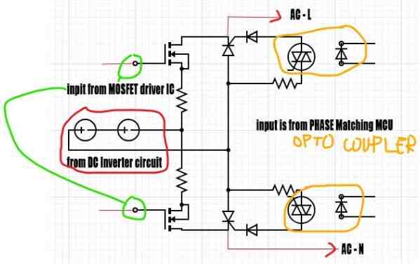
Hello Sir,
I hope all is well with you,
I am interested in your website and I want to publish my article on your website.
Can you add my article?
Please let me know your terms and conditions.
Waiting for your reply.
Many thanks.
Hello Fannii,
The terms and conditions are simple.
The post should not have any external links.
The article should be regarding a circuit idea with a circuit schematic.
Hi, I find your website very informative and enhance learning. Are you open to business cooperation? Feel free to contact me via email. Thanks!
Hi, glad you liked the website, however presently we are not open to guest post submission or any other business format.
Hi sir,
Sir I’m having these small MacPower inverter with 42000mah (155wh) rated, I need to know if I can use 12v 50w solar panel for charging it, the dc input of the inverter is 15v 2A, and one more thing, I’m about to replace the lithium battery inside, hope these is okay?
Hi Tunji,
for a 42 Ah Li-ion battery the optimal charging current should be around 20 amps, but your solar panel can supply a maximum of 50 / 12 = 4 amps which is too low to charge the battery.
Moreover a 12V panel output will not be able to charge a 15 V battery.
OK sir but my charger is rated to be 15v/2A, what can I do sir, and thank you so much for response
Tunji, 2 amp current is very less for a 42 Ah Li-ion battery….it might take 2 days for the battery to get charged.
One more thing sir what can I do with a 200w solar panels 12v rated, 20amp battery and 640w UPS Sir, or do I need to construct my own inverter?
Tunji, You can use the 200 watt panel output to charge your 20 Ah battery. The UPS can be modified to convert it into an inverter.
Thank you so much sir and God bless you sir
You are welcome Tunji!
I am looking for a timer circuit that can be an electronic replacement for a motorised freezer defrost timer. A motorised timer uses a synchronous AC motor and gears that closes output contacts for a short time, typically 10 minutes, to put the freezer into defrost mode.
What an electronic circuit would need is a long timer with a short output event. Ideally 24 hour cycle time and 10 minute output switch time. Timing accuracy and stability would not be crucial, and the event output of the timer could control a relay for switching 240V AC for a defrost heater.
I think a programmable PIC or Arduino project may be one solution, but I have been searching for a discrete components circuit for some while without success.
I appreciate your circuits advice, which are very good examples. I wonder if you have any thoughts on how to make such a long timer.
Kind regards,
Malc
I think the first circuit from the following article will do the job for you:
https://www.homemade-circuits.com/how-to-make-simple-programmable-timer/
Hi,
I am anjali, manufacturer of PCB for Diwali decorative series led.
I am sharing you the image of our PCB and Video of Series in which it used.
Can you please tell me which Code/Number of IC used in this kind of series.
Right now i am purchasing this IC from other which is very costly for us. Please help me.
https://drive.google.com/file/d/1Tn3Qu8w4HxEQjmeQ5dkNktiYdxHEqPA6/view?usp=drive_link
I am not able to attach image, please contact me.
7383269949
Hi,
the google drive link is not giving me access to open the link here because it is not in the sharing mode
Re: Make this Insect Wing Signal Detector Circuit
I am looking at enhancing this type of circuit with a custom tuned coil (receiver) that I have specification on. Can you please contact me to email more details?
You have a great grasp of analog circuits.
Would like to run a couple of specs past you (with diagrams).
Best Regards
Sorry, I wish I could help you but unfortunately I do have sufficient information about this circuit as this circuit was contributed by an external author.
I am considering making a small number of circuit cards (simple ones like in the Insect wing detector. Is your company, hobby, or shop available to take bids? Or do you have any recommendations?
I am old enough, eyesight, to have given up my soldering iron. But, have some small projects and budget.
I wish I could help you, however presently due to lack of time I am unable to accept eternal job offers.
Hi Mr Swagatam !
I need to replace a big and heavy isolating transformer (primary 220V / secondary 220 tap 110V / 1kw ) for sometrhing like a SST (Solid State Transformer) .
Do you have any recommendations on that ?. I couldn’t find anything practical!
Hi Oswaldo, sorry, I do not have sufficient information about this concept so I can’t figure it out for you….
I would like to make a small induction coil for heating water in a cylinder. I am not an electrical engineer so I would not really be able to figure it out. I was not even to understand the parts list in your project above LOL.
Maybe you could build one for me? I would be happy to pay you.
I won’t recommend you to build this circuit, instead you can easily buy a working kit from amazon and use it for your purpose.
good day
i am looking for simple circut design where i can plug an input and the unit will count the beats per minute and display result digitally.
Hi, sorry, I do not have this specific circuit with me that this moment, If I find one will surely let you know.
Thank you for your circuits, I intend to build your Crystal Set with LOUDSPEAKER Circuit and, I would like to add an On/Off Switch with a Led to show when On and Off. Could you please show me where the best place is to fit the switch and led in the circuit also, I presume I would need some resistor ???? inserted to protect the led ? /Also, I intend to use ceramic caps for C1 and C2. is that acceptable? and the 4k7 is just a volume control pot I presume?
Hi, you can put the switch in series with 9V supply positive line. The LED can be put across the +/- lines of the 9V supply with a 1K series resistor.
https://www.homemade-circuits.com/crystal-radio-sets-with-amplifier-circuit/
Yes you use ceramic capacitors for those C1, C2. 4k7 is the volume control pot.
For further questions please post under the above article.
hi.
I presently have some solar panels that are between 33 and 35 Volts each. currant is 8.1 amps I have 2 strings of 6 giving a max currant of 16.2 amps into my inverter. I want to do a DIY hybrid system by charging 10X car batteries in series during the day and applying the stored DC onto my inverter in the evening. charging is.not a problem, but, I need to limit the currant from my 120V battery to the maximum the inverter can handle as it is designed to not have very much available to it in the first place. giving the inverter a potential 500 amp supply is a bad idea. I also need to limit the amps in order to generate watts I am using and to not export to the mains, KW, that I uave spent the day accumulating. so. we are looking at 120vdc but could be up to a maximum of 500vdc and currant limit maximum of 16 amps with ability to choke down to a low level say one amp. without getting too hot so as not to waste energy.
Hi,
I have a few current limiter circuits posted in the following article. You can probably try the MOSFET version and check the response. Make sure to upgrade the MOSFET and the BJT specifications to match the high voltage spec of your application:
https://www.homemade-circuits.com/universal-high-watt-led-current-limiter/
Swagatam,
Here’s a poser for you … have a display with 27 opaque plastic candles, with a small circuit inside, using a 556 to make a small filament bulb flicker. In the base
of this unit, there’s a 15v/4A switching P/S. Each candle has a pushbutton switch on the top to ‘light’ the candle.
There is a coin slot. On the underside of the alum plate with the slot hole are two sets of IR transmitter/receivers to detect the coin drop. This feeds to a small p.c. board with a ‘master’ 555 timer ckt. The idea is that once the coin is dropped, the circuit is energized so one or more ‘candles’ can be lit. I believe the master 555 circuit may be a timer so that after the elapsed period, all lit ‘candles’ are put off.
I have no schematics; the date codes on some of the components date back to the mid-80s. The IR devices glued to the underside of the plate have been broken off due to malicious mischief, and a TIP120 on the 555 board has been shorted … the board has suffered some damage.
Given the age of the components, the lack of schematics, I am charged with making this unit OK again. I do not ‘speak’ ARDUINO or other modern microcontroller. And, doing a part # search I’ve come up empty looking for these individual IR components. Any suggestions are gratefully appreciated.
I’ve thought of a BASIC STAMP solution or using an inexpensive PLC controller, both of which I have vast experience, but I would need a RTC settable to some definable long duration …. 15 mins to 1 hr.
I did see your egg timer solution at one point, just use the ‘front end’, eliminate the oscillator & speaker section.
Thank you.
Hi Karl,
Are you looking for the infrared proximity detector circuit, which will detect the coin and trigger a monostable. It is not difficult, it can be redesigned.
Hi Swagatam,
I have a problem with my BTA-41 dimmer where the variable resistor has already been replaced twice, due to damage. It was damage when I used it to regulate 10A step down trafo for batt charging purpose. Does it matter with schematic itself or bad quality of the VR? Can you Please advice?
The schema: https://drive.google.com/file/d/1FrBaadzMpfuSE14VfRdKf3VLS95GUqoI/view?usp=drivesdk
Thanks.
Hi Awak,
Your VR is protected by the series 4k7 resistor so it should not get damaged. You can do one thing, put the lamp in series with the LIVE wire before the bridge rectifier and check the response. Alternatively you can try by modifying the following design and check how it works:
" rel="ugc">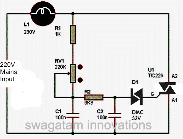
Thanks for response.
How many watts of lamp? And what kind of response should I check?
Thanks.
In your original diagram I can see a lamp connected on the right side of the circuit, use the same lamp and connect it in series with one of the input wires of the mains AC supply. With a load in series at the input side the VR will not get damaged, or you can try the circuit provided by me earlier.
Ok I’ll try. But fyi, this dimmer has been used longtime with my fan, has no problem, but when used for battery charger, it is damaged.
Actually using a mains AC based dimmer is strictly not recommended for charging batteries, your battery can also get damaged.
Can you please recommand the circuit for regulating battery charging? If has, a simple one.
Thanks.
What is your battery voltage and Ah specification, and is it a lead acid battery?
12V 10Ah. Yes.
In that case you should use a simple LM338 IC based power supply to charge your battery. Set the maximum charging voltage to 14 V and then you can safely charge your battery without any issues. The maximum current must be controlled to 1 amp, and input DC can be from an SMPS or a transformer based power supply. The input voltage must be around 16 V to 18V. Here’s an example diagram: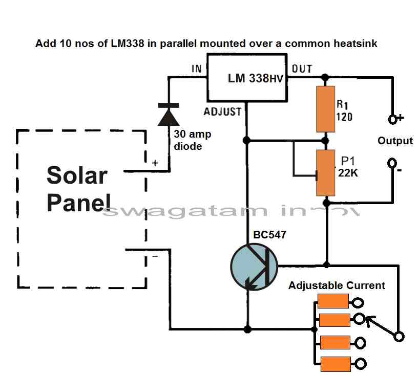
" rel="ugc">
Hello.I want to design the pcb file of this circuit..but I need calculations for board thickness.track thickness.distance between tracks and number of coils..please guide me
Which circuit are you referring to?
Here’s what I need: The circuit in this link is the basic idea (https://www.homemade-circuits.com/logic-sequence-controller/) but instead of a free running oscillator to increment or decrement the sequence, I need to be able to step through the sequence using one of 2 momentary switches – an ‘Up’ switch and a ‘Down’ switch. They would obviously need to be bounce-proofed. I would like to be at the ‘lowest’ state when powered on. Show me what needs modified or added to accomplish this.
thanks,
Bob
The above design is not my design actually, and I can’t figure out how to modify this for using with a two switches, as per your requirement.
I have searched but was unable to locate a circuit that I could build that would display the total life run time, remaining runtime (counter reset on user input) and voltage output for a portable gas generator.
I figure I could tap into one of the output plugs to trigger a counter for life time and remaining run times as well as the available voltage.
>The ‘remaining runtime’ is a countdown timing for when the oil needs to be changed and the duration is user input.
>The ‘total life run time’ needs to be stored in memory.
>optional date/time would be nice but only is simple to implement.
Thank you.
Sorry, that looks a bit complicated, I do not have this circuit with me right now.
hello sir, I tried to make a drill speed controller, can you please elaborate on the bridge rectifier SCR speed controller circuit, like should allthe 3 lega of the potentiometer be connected etc. please can you redraw the circuit diagram with proper + , – symbols. thank you.
Hello Abhishek, please ask this question, under the same article where the schematic is located.
hi sir
please note my Mobil number 9440668851
I have a requirement to make solar induction stove
Hi Harish, I would recommend you to buy a readymade induction heater assembly and then connect it with a solar panel, because building an induction heater can be quite complex.
to me I want rf discharge circuit and I saw online that you have it, I want it. how works. Run it in a copper box. Can it? how That is to do. to me Say it has. Radiation goes to a torch bulb 2.5 v 5amps fuse. Please tell me if you can do it. What is the rate and where is it available?
I only have the circuit idea, I do not have a prototype built. I cannot build it for you.
You will have to contact a qualified engineer and get it constructed for you.
hello swagatam I always do electrical installation, but the challenge I have is to make a circuit that turns on all AC bulbs in the house and the circuit can sense when ac electricity gets off it will automatically turn on the DC bulbs line so I wanted you to design a circuit diagram thanks
Rashid, you can try the following concept:
" rel="ugc">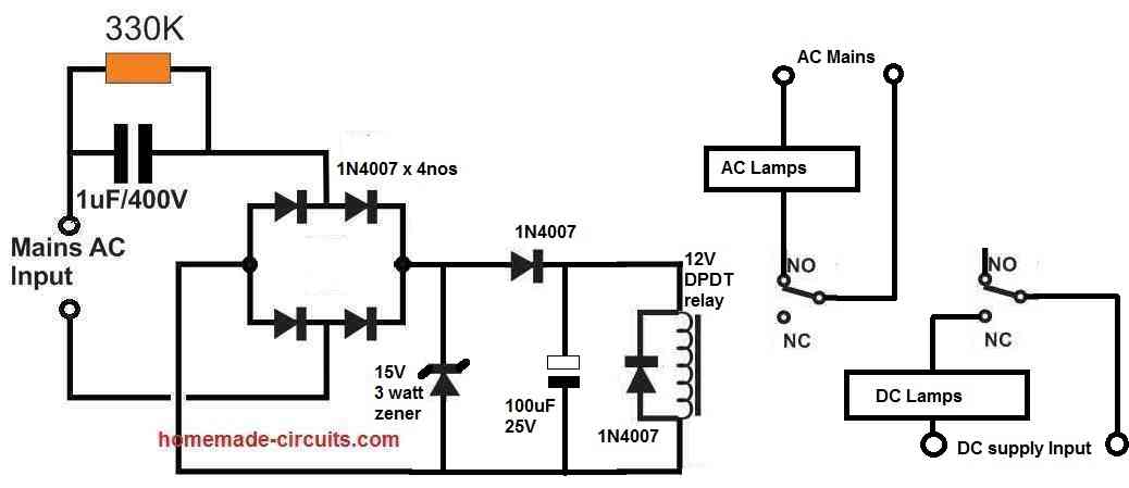
swagatam I wanted you to design an automatic turn on inverter that allows AC current flow to the tv and decoder and it automatically turns on the inverter to supply AC power to the tv and decoder when AC power goes off
Rashid, If you already have the inverter unit with you, you can convert it into an UPS using simple relay changeover as explained in the following article:
https://www.homemade-circuits.com/how-to-convert-inverter-to-ups/
Hi
What is a circuit that will variably dim a 12v DCvhalogen bulb not using the pulse method that turns it on and off for varying parts of the cycle, but changes the brightness of the bulb. (Is this accomplished by reducing the voltage?) I am doing an art project that will require different levels of brightness in different venues depending on the size, ambient light, etc. of the venue so I want to be able to set the brightness exactly each time. I need to use a halogen bulb because it is a point source of the light. It will be on for a maximum of 2 1/2 hours at any time so I could use a lead acid battery (using 10.5 amp-hours in the 2.5 hours) so it is a straight DC source. I would appreciate the advice. Thanks.
Hi,
If you use the voltage control method instead of the PWM or the pulse method then the power usage won’t be efficient and your battery would deplete faster. Therefore, a PWM method is the recommended technique. The fast ON/OFf of the lamp cannot be identified due to persistence of vision.
dear sir
yours conact number plesae
Murugesh, you can discuss with me through comments, I will be happy to help!
Dear Swagatam,
I was careful to explain that I cannot use the pulse method. The rapid movement of some objects will leave a stop motion effect if I use the pulse on-off method.
I also explained that I don’t care very much if the energy use is not efficient because the light will only be on a short time–2.5 hours–and my lead-acid battery can handle it.
So I am still looking for an anwer to my question to variably dim a 50w 12v halogen bulb, as I wrote it.
Thanks.
Marc H
Dear Marc,
I don’t think you explained the above things in your previous comment.
Anyway, if power efficiency is not an issue, you can try building the 1st circuit from the following article:
https://www.homemade-circuits.com/how-to-make-versatile-variable-voltage/
For further questions please ask them under the above linked article.
Good day Swargatam,
Can you advise on how to build a circuit that has a 12V SLA battery and 2 capacitors (super perhaps), as well as an oscillator? The circuit works as follows: in one cycle, the capacitors are connected in parallel, and the battery charges them up to 12V. In the next cycle, the capacitors are connected in series and discharge into the battery. All the while, a motor or power output (transformer/inverter circuit) is powered by the charge/discharge cycle. So we are recycling the power in the battery while using it to perform useful work. For reference to the circuit’s theoretical proposition, check this URL: http://www.free-energy-info.tuks.nl/Chapt5.html. In the page, search for the term: Bozidar Lisac’s Power-Boosting System.
I tried creating this circuit, using a latching DPDT Relay switch and a 555 astable oscillator circuit for the switching, but I want to benefit from your great and benevolent experience.
Thanks so much for your anticipated help!
Hello Ikechukwu,
I do not have any practical experience with free energy devices an concepts, so it can be difficult for me to advise on these subjects. I would recommend you to visit the free energy forums to get the answers from the experts.
need rf discharge circuit sir is available frome ur side
I have a circuit but it is not tested by me. Here’s the link:
https://www.homemade-circuits.com/making-strong-rf-discharge-circuit/
I Want to convert 4-20ma current output coming from humidity sensor to 0-3.3v using Rail to rail opamp so I cad read it to ADC ic connected to my Raspberry Pi. Any circuit Idea ,please help me in it.
Thank You
Arijit
I don’t have the exact circuit, however you can refer to the following concept and modify the designs accordingly:
https://www.homemade-circuits.com/light-meter-circuit-with-led-bar-graph/
Could you please explain this circuit. It’s driven by a PIR sensor. It’s supposed to function as an opened ring counter. Wouldn’t all the transistors just conduct constantly?
" rel="ugc">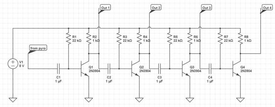
Yes, all the transistors would remain permanently switched ON due to the presence of the base/positive resistors.
Thanks for the reply. I’m wanting to use a pir sensor with an h-bridge to automatically control a 12-volt motor to open then shut a valve after a desired amount of time. After the pir-rc signal I thought to use a delay then on stage to then initiate another on, delay, off to close the valve but I’m not sure how or if this could be done with basic discrete components. I’d appreciate any circuit ideas for sequential timing circuits to accommodate the mentioned task.
I could not understand the following sentence:
“After the pir-rc signal I thought to use a delay then on stage to then initiate another on, delay, off to close the valve…”
Please explain in a proper way.
I thought to open and close the valve I could maybe use 3 resistor, capacitor timing circuits. One being from the pir module and using its output to open a mosfet to drive the motor. Then to keep the valve open for a desired time I’d use a delay, then ON followed by another ON delay OFF circuit to close the valve. As mentioned, I’m not sure if this could work and I’m really just wanting to know if there is a way to automate a valve without IC’s.
A motor is not required to open or a close a valve, a valve can be directly operated with a 12V supply to alternately open or close. The delay timing may be possible but not through an H-bridge, that looks difficult.
By valve I mean a water hose shut off valve and being rotational. I’m wanting to make a home-made motion detecting sprinkler. I think commercial ones do use a slide valve which is opened electrically and held closed by a spring. Is that the sort of valve you were referencing? I know I could use Arduino or such, but I’m more interested to know of a way to do this without software. Thanks again for your correspondence.
Yes, I was referring toe solenoid controlled water valve system, which won’t require a H bridge rectifier rather can be controlled using a single MOSFET or a relay. The switch OFF delay and the switch ON delay can be implemented using a transistor circuit.
Hello and thanks for reading my comment. Swagatam! Also sorry in advance for my English because I am from Greece. I want to make a circuit with 9V input. It has a microphone and a 20Ω 200mW speaker. Also I must put 3 bjt transistors : one with common collector , one with common base and finally one with common emitter.
Thank you Nick, I do not have the exact configuration you are looking for, however there are a few MIC amplifier circuits explained in the following article which you can refer to:
https://www.homemade-circuits.com/small-amplifier-circuit/
Thank you very much!
Hello Swagatam,
I came across your website while searching for DIY projects.
I want to build an UPS for 5 KW (240AH / 300Ah x 4 batteries ) (Lithium Phospate batteries) project.
Is it possible to help in creating a circuit diagram and components required.
Below are the functionalities required.
1. Inverter
2. Battery Charging ( Auto on / Auto Cutoff )
3. Minimal switch over time from main to Inverter
4. Over load protection,
5. over voltage and over current protection
6. MCB inclusion for safety.
I really appreciate if you can help.
Battery pack will be separately created with BMS
Thanks in advance.
Hello Mahadev,
A 5 KW inverter will need to be built using ferrite core transformer, which can be very complex. The first step would be to build this circuit successfully, the rest of the things can be then built and integrated step-wise with the inverter without much difficulty. You can check out the following circuit and see whether or not it is feasible for you to build:
https://www.homemade-circuits.com/5kva-ferrite-core-inverter-circuit/
Please provide me a circuit for efficient 3W led flashlight, with a fuse protection using alkaline batteries cell 1.5 V two cells or 3 cells whichever gives best efficiency for batteries. The inside temp of Flashlight should also not get high.
If your LED is a standard 3.3 V type then you can directly connect it across the 3 V battery via a switch. Make sure to mount the LED on a appropriate heatsink.
can I use a PWM for better battery life. Any circuit advise for it please.
If you use PWM, the LED illumination will decrease, depending on the PWM duty cycle.
sir please let ask you about 2 circuit
1 simple clap switch diagram
2 simple solar street light automatic circuit
Abdul, You can see the following links:
https://www.homemade-circuits.com/make-simple-electronic-clap-switch/
https://www.homemade-circuits.com/3-simple-automatic-street-light-circuits-explored/
hello sir I thank you for your knowledge that you have helped alot of people, but please sir I was requesting for your help to help me please because this list of things have always been troubling me:
1. how to make a dc to dc converter of 13v to 12v ?
2. how to make solar charge controller of 100 watts or a solar charge controller that can handle 2 solar panels for which each solar panel shall be 100w , so if we combine 100w + 100w it will be 200w , please help me sir
Thank you Rashid,
1) You can reduce 13 V to 12 V by simply adding two rectifier diodes in series with the positive supply line.
2) Can you please provide the load specifications or maybe the battery voltage and current specifications?
please swagatam make a design for the first controller of 100w panel charging 100ah battery,
and you can help design another controller that can charge 150ah battery
Rashid, you can try the following circuit. Adjust the 10K preset to produce exactly 14 V for your 12 V battery:
" rel="ugc">
thank you so much for your efforts in helping us ????
but I still want to disturb you about something, some few weeks ago I had seen in a certain website that it’s possible to make an incubator using 25w bulbs because I had seen a certain diagram incubator temperature controller using lm358 …etc.
please swagatam if it’s possible please help to design a better temperature controller for an incubator because you are the best
No problem Rashid,
The LAST CIRCUIT from the following article will perhaps fulfill your requirement:
https://www.homemade-circuits.com/how-to-build-simple-electronic/
your knowledge is above thank you so so much and thank you again
No problem Rashid, I appreciate your kind words.
swagatam I’m going to begin making it and it will be good if it will charge the 150ah big battery I have minus discharge at night and the types of resistors I can use to replace the 10k resistor you told me, now the other question I have is I saw an arrow pointing the middle of a resistor in some diagrams
Rashid, in the following diagram, the 10K can be a 3-pin preset or a trimpot. The arrow head indicates the center pin of the preset
" rel="ugc">
Preset image:
" rel="ugc">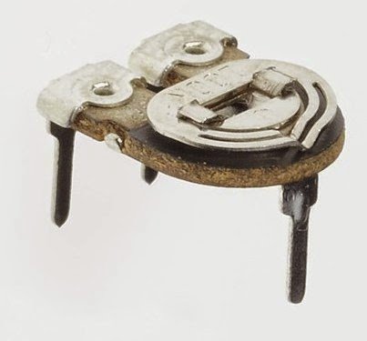
hello swagatam I’m again back to you, requesting you to please design an incubator that can use solar or dc electricity
Hello Rashid,
Please post this question under the following article, I will try to help:
https://www.homemade-circuits.com/how-to-build-simple-electronic/
how many volts can charge a 13volt 22ah battery and can I use the very circuit you gave to me
The previous circuit using 2N3055 transistor is too big for a 22 Ah battery….you can use the LM317 based circuit explained in the following article. You will have to replace the LM317 with LM338 IC, the pinout configuration will be the same:
https://www.homemade-circuits.com/how-to-make-current-controlled-12-volt/
ok thanks, but how can we make a sun tracker for solar panels, I mean the tracker that can carry a weight of 2.3 kilograms because 100w solar panels weigh 2.3kg
It is possible to make a suntracker, but it may require knowledge and skills in mechanics and electronics. You can refer to this article for more info:
https://www.homemade-circuits.com/how-to-build-dual-solar-tracker-system/
SUBJECT : 12V EMERGENCY UPS FOR A DVR + CCTV CAMERAS
Hello Mr. Swagatam
Thanks for providing this wonderful service as I have visited your site several times to learn stuff in the past. I have a problem I wish to discuss with you and when ever your are free or sufficient time you can give me a tip or a reference so I can resolve the issue.
I have purchase for CCTV cameras for home and a used DVR. All cameras and DVR (3 Amp) are rated for 12V and 4.5 Amperes (Each Camera 375ma so (375 x 4) + 3 Amps for DVR). However during power failure the security cam stops so I though that I can put a 12V, 40Amps car starter battery at work by connecting Positive and Negative with relevant DC sides so in case of a power failure the DVR and cameras should work without any interruption.
However the Switch mode power supply unit rated at 7 Amps for DVR and Cameras is measured exactly 12V but battery charging needs more that that (14 to 15v) but then a higher voltage may cause damage to cameras and DVR as well. I wish to avoid LM317 or similar circuits to avoid due to wastage power in heat and also relays as these may spark due to heavy amps consumption. (I do not have any 220v inverter etc. and I think that it may be an overkill as a single battery if more cost effective). By using a battery I can also light up some form of LED street lights in as emergency during power failure.
By reading your articles, a simple solution was to use a battery charger (around 4 amp as 10% charging current for 40 Amp battery) to charge battery and also to power up the cameras and DVR but four heavy Duty Diodes in series to reduce voltage (i.e. 0.6v x 4 = 2.4 v) however the charger (also a DIY. solution) may not be as good as switch mode power supply that came with DVR. I want an elegant and safe solution so want suggestions from you. ( I understand soldering well and have done some projects without any problems so even some tips or some of your suggested articles may work for me. I can mix / match to get desired results).
Thanks and regards,
Thank you Abdus,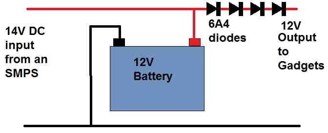
Your idea looks perfect to me, and can be configured as shown in the following diagram:
" rel="ugc">
However there’s one drawback in this circuit….during absence of input power if the battery voltage drops to 11 V then the output to the camera would also drop to 9V because of the series diodes.
Thanks. That was quick. However I cannot say that it’s perfect as it has the draw back u mentioned. Do u have any suggestion or tip as how I can overcome the problem. Moreover u have shown the SMPS as 14v but it is 12v actually. Regards
You can decrease the number of diodes to two so that the camera gets a maximum of 13 V which should be easily tolerable by the cameras.
The SMPS must have an external adjustable preset control to adjust the output voltage to 14V, otherwise it won’t help. However preset adjustable SMPS are available in the market, you will have to search for it.
Please sir,
I need a complete project write up for a 1kva pure sine wave inverter.
Hi there, im trying to create a solar light that turns on at night and charges a battery during the day. Im trying to keep it as low cost as possible. I found your solar light design. https://www.homemade-circuits.com/simplest-automatic-led-solar-light/. I was able to get it working, kind of, with your second schematic. Im wanting to light 6-8x 1w 5v leds with 2 or 3x 3.7v batteries in parallel to keep the lights running at least 4-5 hours. Im using 3x 5v solar panels in parallel to charge the batteries during the day (I’m not sure if that’s enough power but I can add more panels if needed). Eventually, I want to turn it into a PCB to keep it clean and all I would need to do is solder on the solar, LEDs, and batteries.
Hi, I would suggest you the following circuit instead. Adjust the R2 to produce exactly 4.1 V for the battery, and use single LEDs in parallel instead of 3 in series.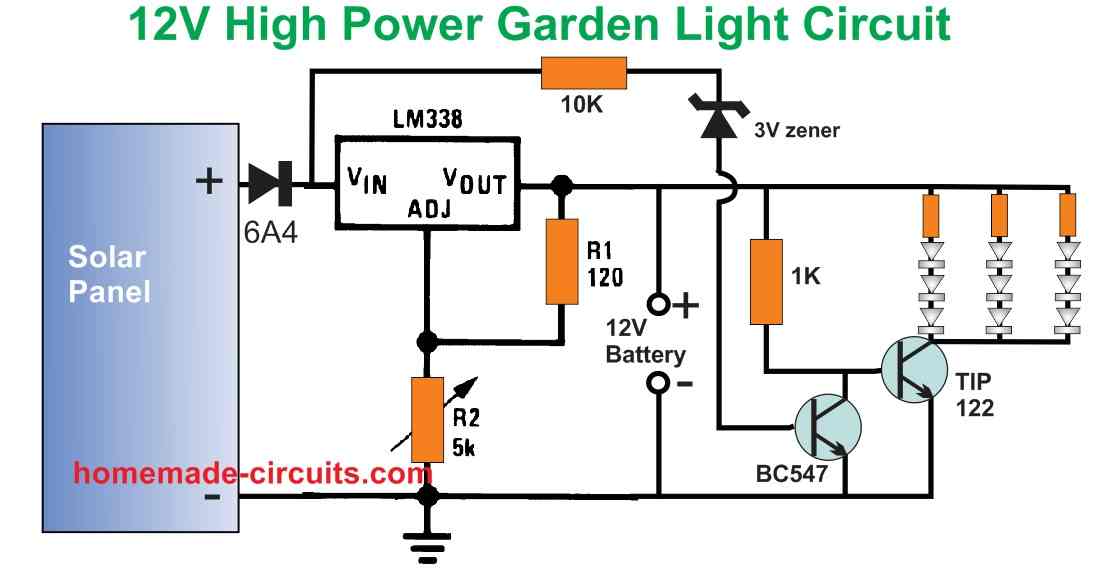
" rel="ugc">
Im not trying to use a 12v battery, just the 3.7v’s I have. The project needs to be pretty compact.
You can replace the 12V battery with your 3.7 V batteries. That is why the LM338 output needs to be adjusted to 4.1 V for controlling the full charge level of the battery. The LM338 is needed to provide a regulated charging supply to the Li-ion batteries. However for this circuit a 5 V solar panel might not work, you might need an 8V or 9V solar panel.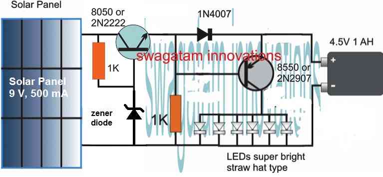
If you don’t want the LM338 circuit, you can try the following design:
" rel="ugc">
Adjust the Zx zener value to get precisely 4.1 V across the battery points (without any battery connected)
Hi,
I am trying to draw up a schematic for a continuity tester for connectors w/flex prints. We have a 69 Pin and a 37 Pin connector that we solder a flex print to which we have been checking each pin and flex print trace one-by-one with a VOM. So, I need to automate this to check all the connections at once. So, I am designing a device that has a mating connector for each 69 and 37 pin connector. These will be wired to one side of each bank of LED’s and the other with the power supply and resistor. For now I am wanting to use a 12v supply but this can change. I am using RED Lumex LED’s P\N SSL-LX3054SRD that are rated 1.85v with 2.5v max. Vf at 30MA. Now I also need to add a test button to check that all the LED’s function before each test. Can you help?
Hi, The cathode ends of the LEDs would need a ground connection for them to illuminate. How would you arrange these ground connections through the connectors or while testing each LED?
The ground connections are connected to the connector through the flex print. Do you have a means to submit a pdf? I can show you what I have.
Can you please upload it to your Google drive and send me the link here. I will try to figure it out.
Never mind that idea has been shot down now. Thanks for your input!
Can we use this office call bell in hospital..
Yes you can….
Good morning engineer. I am a person who started using LED spotlights already more than 10 years. Every now and then someone breaks down. I’ve realized that in almost all cases what’s broken is the power supply. Since I have so many, I thought maybe I can reuse them by making a bar to use to light up the garage. I don’t want to use a transformer though. It’s possible? Could you please give me a schematic I can make? There are 4 LEDs for each lamp and the declared power is 4*2w. Thank you
Hi Rosario, You can try the following circuit. You can reduce C1 to 105/400V or 1uF/400 capacitor for getting 50mA for your 4 LEDs which should be connected in series:
" rel="ugc">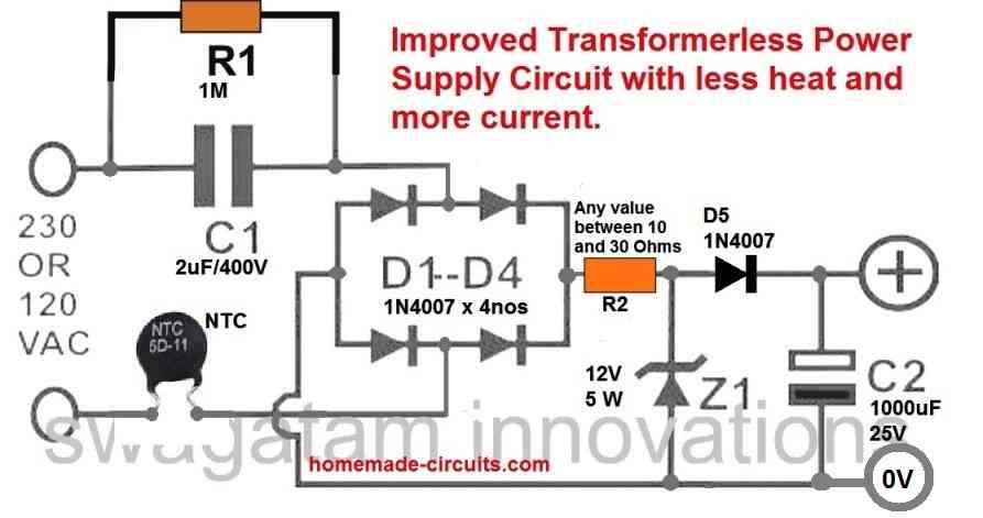
Please note that this circuit is not isolated from mains AC therefore is extremely dangerous to touch in an uncovered and switched ON condition.
sir your code for playing song on dfplayer mini module with 5 buttons worked can u provide me an code for which two ultrasonic sensor used ultrasonic sensor 1 for controling volume and ultrasonic sensor 2 for play/pause and when the hand is swapped through 1-2 it should work next and when the hand is swapped through 2-1 it should work as previous
i’m trying this for my project
pls try to help sir an request to please reply as soon as possible
Hi Sudarshan,
My Arduino coding skills are not good, so it will be difficult for me to solve your problem. All Arduino articles in this blog were purchased from external sources.
many thanks for your help.
I want to make an inverter welding machine using tl494 or sg3525 with a 60v DC output. In my project I want to use a ferrite transformer. And i want to be adjusting and reducing the current at the out put.so iam requesting for your guidance and related circuits
Sorry, I do not have the necessary information for this project.
Hello,
I am not a circuit designer, only a Dad. I am making a couple toys for my children that require a Simple Delay Timer Circuit. I believe your design will be perfect for these projects.
However, your 12V DC power is too much for my projects. I have size and recharging issues that are stopping me from using a12V power source. Do you have a schematic of your Simple Delay Timer Circuits that uses 1.5V, 3V or 5V? Well, I don’t really need a new schematic. A new parts list with different values for each part in your 12v design is all I really need.
If you could provide a link or list for me to view would be most appreciated.
I thank you for your very informative web site and helping me and my kids.
Doug
1-725-267-4095
The 12V circuits can also work with 3V supplies, so no issues with that.
Can you please tell me what kind of delay do you require? Once power is switched ON, should the load switch ON instantly and then switch OFF after some delay, or should the load switch ON after some delay and remain switched ON.
Greetings and Salutations Swagatam!
I am currently trying to make my own power supply that will run from AC to DC and be able to supply at least 0-100 amps variably, but have not been able to locate a schematic for such a cause. I was wondering if someone could point me in the right direction or help with the design of such a board. I was thinking a rheostat would be needed for the current output as a potentiometer would not be able to support the amount of current passing through a pot, from what I have gathered. I would like to have a digital display that would read the volts / current output accurately so I can write down the test results.
The few that I have found online are ranging from 800+ dollars which is a little more then I care to spend at this point when I know I can build one for cheaper and learn a thing or two about circuits. Any help you can provide is welcomed. And as for parts and pricing, I don’t mind spending a bit to get the job done.
Thank you Michael,
100 amp is a huge amount of current and a cheap linear power supply might not be suitable at this level of current, because a linear power supply may get immensely hot at lower output voltages which can be unmanageable. The only option is to build an SMPS type of power supply.
However, presently I do not have a 100 amp rated SMPS power supply with me, If I happen to get one will surely let you know.
Thank you very much for you insight, I did see a 50 amp build SMPS that I was thinking about building. It should be enough for what I plan to accomplish. I was hoping that there was some schematic out there I could follow but I’ll have to design and make one up myself. Thanks again for the insight.
Sure, no problem, I wish you all the best!
Hallo there.
I would like to know what the light intensity range of these circuits are. Will the preset in circuit 1 for example adjust to switch on at full sun and not before?
Will it then switch off at a level (preset if possible) with less sun but not darkness needed to switch off?
It will be interesting to know the light strength limits for switching on and off.
Thanks.
Best regards.
Hi,
Can you please show me the schematic which you are referring to?
Hello Swagatam,
I would like to build a ~100mA constant current regulator using an LM350. The purpose is to provide a trickle charge to a 12v vehicle battery that is sitting for long period. I have a rectified/filtered circuit that outputs 22vdc@500mA for the LM350 Vin. The current limiting resistor at the Vout is what I’m having difficulty with. I’d like to use an adjustable power resistor so I can tweak the current output, I just don’t know what value and wattage rating to purchase.
Thank you,
Jack
Hello Jack,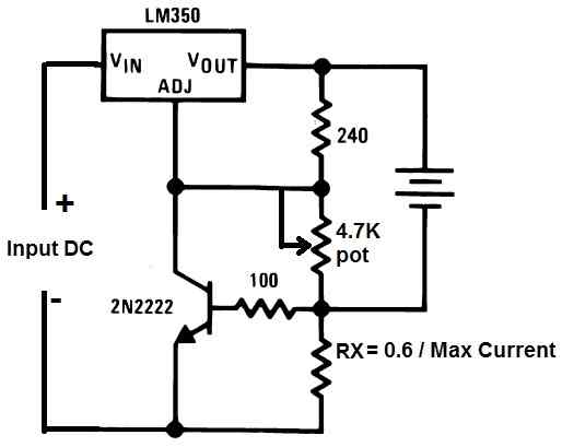
You can try building the following circuit which should solve your roblem.
" rel="ugc">
Here RX is the current limiting resistor. All the resistors are 1/4 watt
Thank you, I’ll comment after I get the circuit built and tested.
Jack
Finally secured parts and finished the circuit which works great!
" rel="ugc">
I ended up making RX out of (5) paralleled 100 ohm 1/2 watt in parallel with (1) 100 ohm 1/2 watt trimpot which gave me the ability to fine tune the trickle current.
Thank you so much for your help.
Jack
That’s great, Glad you could build it successfully! All the best to you!
Hello, what minimum power rating does the 4.7k pot need to be? Can it also be a 5k pot?
Thank you,
Jack
It can be any ordinary or standard pot, yes a 5K will also do.
Dear sir,
I have an old PANASONIC VHS Videorecorder with power supply broken.
I managed to find the schematic but I need your help.
I don’t have a professional oscilloscope, I have a DSO138,
and with the schematic I don’t know if I can verify the indicated test signals.
If it’s possible I can post the diagram and description of what I’ve already done and checked.
I hope you have the chance to help me. All the best
Claudio
Hi Claudio,
Sorry, since I have never opened or checked a panasonic videorecorder, I know nothing about its internal functioning so it would be very difficult for me to troubleshoot your problem.
Thank you Sir, The problem is the power supply board of which I have the original electronic diagram
and therefore with your knowledge you would have no problem understanding the possible problem or right test.
As soon as I opened it, I saw that the output resistor of the rectifier bridge had burned out,
I changed it but it was still shorted, so I decided to go deeper into the activity to learn these circuits better.
If I link the schematic could you give me some suggestions?
Thanks in advance.
Claudio
Hi Claudio, You can send the link but most probably I won’t be able to solve it because the power supply would be ab SMPS and all SMPS circuits have different designs an mode of working, so understanding a particular design and be a lot of work. You can send the link if possible if i will try to help.
I have built a hi-fi turntable, and have an electric motor running from a 12 volt battery. I bought a PWM speed controller off Ebay, but while it does control the speed, I can not get it to accurately adjust the speed to 33.3. Can the control unit be modified?
It seems that my motor only requires a couple of volts for the correct speed range. I noted that the video of the single-transistor control unit on your site only works from 3 volts upwards.
I don’t think your circuit can be modified. If you want to control the speed by varying the supply voltage then that is also possible. You can try implementing the following concept: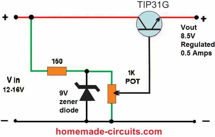
" rel="ugc">
Thank you. That is simple enough to try.
Sure, no problem…
Can I use a TIP31C instead of the TIP31G?
Yes you can…
Thanks again.
– How to Build a 400 Watt High Power Inverter Circuit
I want to build above article circuit.
In part list have this relay
RELAY = 24 VOLT, SPDT
If anyone know a eshop to buy it.
My home is in Greece
Hi Swagatam sir
Hope you are well
I am making long range ultrasonic distance sensing project, I need 10m range with good accuracy.
Application: On motorcycle in external environment, while in motion
1. I used HC SR04 module (range 4m). It does not work beyond 4m.
Q:
Can you recommend ways to increase range of HC SR04 (https://robu.in/product/hc-sr04-ultrasonic-range-finder/) either via the circuit (maybe adding additional components or playing with hardware OR via changes to the coding)?
2. I found this long range (18m) ultrasonic sensor:
https://in.element14.com/multicomp/mcusd16a40s12ro/transceiver-40khz-16mm-metal/dp/2362677
I checked the documentation – it does not contain any details or circuit diagram. This is a standalone sensor without PCB, hence I need help.
Q:
Can you please guide me how to interface it with Arduino because it does not come with PCB or any guiding documents?
3. I am also thinking to use the HC SR 501 PIR sensor:
https://robu.in/product/pir-motion-sensor-detector-module-hc-sr501/?gclid=Cj0KCQjw8qmhBhClARIsANAtbofyBdyMKzv6J8oVp6eM1FzvGbdwCoY-5mHvvAehqCD935kLGGXzufsaAr6DEALw_wcB
Q:
Do you think a PIR sensor will work?
Hi Vikram,
Unfortunately I have no idea how to increase the range of a 40kHz ultrasonic transmitter.
However I think the ultrasonic device could be replaced with something like a tweeter device and then experimented for enhancing the range.
You can try one of these circuits using tweeter and check if the range increases or not:
https://www.homemade-circuits.com/best-ultrasonic-transmitter-receiver-circuits-for-all-hobbyists/
I think PIR is much better, and has a higher and stronger range than an ultrasonic device.
sir how to make simple digital programmable timer circuit
on/off circuit
please help me circuit diagram
Abdul, You can try the following circuit
https://www.homemade-circuits.com/simple-digital-timer-circuit-with-2-digit-display/
sir another question this programming I can I use in diesel engine on an off engine
Sorry, I have no idea how a diesel engine can be switched ON/OFF. I guess it can e done with a relay switch but not sure.
sir you can remember inthe company having diesel engine when electricity is come engine stop working after electricity is off engine start working this programming circuit I mean sir
thank you for
replay
Abdul, diesel engine requires a complex start stop switch mechanism, which cannot be implemented with ordinary relay switches, because diesel engine will have a CDI also for starting.
Hello! I have a project at school and I am not very sure how to do it. I need an embedded system to test how many on/off cycles a light bulb(preferably led) can perform before it breaks down. I also need to use a solid state relay preferably with zero detection powered from 230VAC and wirelessy controllable. The system contains sensors and some common socket. I am not sure how to connect The components. Could you help me? Thank you in advance.
Sorry, I am not good with embedded systems so it will be difficult for me to help you with this subject.
Hi Swagatam:
My name is Jose and I live here in the Miami, Fl area in the United States.
I have been seeing several of your projects on your page and I find them very interesting and excellently well explained. Congratulations
I am writing to you since I assemble (manufacture) some small machines to sharpen scissors for beauty salons and to sharpen knives as well.
These machines use a reversible 24VDC brushed motor or some occasions 90VDC with TENV armature and 13AMP.
Due to space issues inside the container, I need to use an AC/DC transformerless motor speed controller that also admits a switch at the output and before the motor to be able to change the current clockwise and counterclockwise.
I consider that you can design a type of controller like the one I need.
I await your response to provide you with all the information you need, photos and videos.
Thank you
Jose
Thank you Jose,
You will need a 24V 13 amp SMPS power supply for your motor which will not be a small unit, it will be at least 8 by 5 inches in size.
The reverse forward operation of the motor can be simply done with the help of a DPDT switch.
Let me know if the above factors are OK with you?
Hi Swagatam, thank you for replaying me.
Right now I have pictures of a unit I’m using, I’d like to send them to you so you can see what I think I need.
But where would I send the photos?
Thanks
Hi Jose,
You can upload the pics to any online free image hosting site, and provide the link here.
Hi Swagatam,
Here are links to the photos of the machine that I I use it regularly, it works well and the speed control makes the motor work well.
With something like this or a little better I would be happy, I don’t think I need more.
I tried to show you as much as possible that the PCB has, I hope it is. Enough, if you don’t tell me and I’ll see what to do.
The mosfets say: 54008L ODJH9
Capacitors: 104K 250L
Big Diodes: MCC 6 Au
Thrystor: 2N6027 424
https://we.tl/t-XtBsaoHAqB
https://we.tl/t-2UaRd4GeSz
This type of motor speed control is what I want since it works well, or at least that you suggest something different.
Thank you, I await your answer
Hi Jose,
I can see the images now.
From your explanation, I guess you need a speed controller circuit along with a reverse forward control for your 24V 13 amp DC motor? right?
However the power supply unit of 24V 13 amp will be quite large which cannot accommodated inside the box that you have shown in the image.
Hi Swagatam,
Here are the photo links:
//we.tl/t-XLBsasHAqB
//we.tl/t-ZVaRd4GeSz
In them you can see the machine that I usually work. The exterior measures 8x8x8 inches.
Inside you will see the motor speed control and two switches, one of them is the 110VAC outlet and the other is the one that controls the reverse foward of the motor.
In the photos I tried to see as much of the speed control as possible, but if it’s not enough, tell me and we’ll take others.
The mosfets say: 54008L ODJH9
Capacitors: 104K 250L
Large diodes: MCC 6Au
Trystor: 2N6027424
I hope this helps
Hi Jose,
The image links are not opening, it is showing “page not found”
From your previous explanation it seems you want a reverse/forward control for your motor, and your motor specifications are 24V, 13 amp.
Is it right?
Hello Swagatam sir
I am Saikat, I am using this website since last 2years for my projects purpose. Today I have tried the circuit for Speed control of 3-phase induction motor using zero crossing opto-coupler from https://www.homemade-circuits.com/3-phase-induction-motor-speed/ this site. But I can’t vary the speed of the motor using the pot. Can you help me out please? I am using BTA26 TRIAC instead of FKPF12N60 because this was unavailable.
Waiting for your reply
Thank you Saikat,
Remove the PWM 555 connection from the optocouplers and try to switch ON/OFF the optocouplers manually through an external 5V or 12V. Make sure to use a series 1K resistor with the signal.
Please do this and check whether your motor is switching ON/OFF or not in response to these signals.
THANK YOU SIR.
March 30, 2023
Hello sir
I have tried this method by applying 5 to 12 v manually to opto-coupler but the motor runs without ON the opto-coupler and does not vary with ON/OFF condition.
Can you please give me the solution?
Why the motor is running without giving gate pulse to the TRIAC?
Please solve my problem.
Thank you.
Hi Saikat,
when you apply 12V to the optocoupler, the motor should operate continuously, when you remove the signal the motor should stop.
The opto coupler triac circuit is taken from the datasheet so it should work.
Try separating the 3 optocouplers and check them individually with a bulb, and by supplying a manual ON/OFF signal to the LED side.
If it doesn’t work then the problem is with your oprocoupler circuit.
Hello sir
I separate the opto-coupler circuit and connected with the lamp using TRIAC but it doesn’t work then I tried a new opto-coupler but also the same thing happened.
Please tell me what should to do.
Hello Saikat,
If the single optocoupler triac circuit is not working for you then unfortunately I cannot do anything, because it is directly taken from the datasheet of the optocoupler IC.
You can refer to any other datasheet such as this, all show similar switching diagram. I hope you have connected the external triac MT1, MT2 pins correctly??:
https://www.farnell.com/datasheets/1806097.pdf
hi,
I have a little challenge for you, if you accept.
here the specs:
I want to make the same ammo counter display of the M41a (Aliens gun)
* 2 digits
* counting down from 99 to 00 by hitting the trigger (1 digit with one clic and decounting by maintening the trigger)
* Time between each digit down : 1/4 second
* and lastly, a reseting button to 99
(sry for Bad english, I’m french)
thx Maurice
Have a nice day
Hi,
You can try searching for “2 digit up/down counter circuit”, you will be able to find one.
Hi;
I have a project that I need help creating the circuit and designing the circuit board.
I’m also willing to pay someone to help with this as it’s above my electrical engineering levels.
This is what I’m trying to create, a simpler version of this weed killer: https://rootwave.com/portfolio-item/rootwave-pro/ Their portable version uses a generator and runs on 220v, but I think for average garden weeds, a lower power version running on 120v (60hz where I live) would do nicely.
After reading a lot about it and their research, I found somewhere that their patients are for weed killers over 18KHz at 2K to 5K volts.
I’ve spent a lot of time selecting some of the main components I think will do the best job but need help in creating the full-bridge circuit.
I’m targeting an output at 18KHz, 5000v with an input of 120v 60Hz for the weed fryer. I may like to tap the output transformer midway too, so as to have a mid and high output voltage.
Main transformer core: Ferroxcube U126 x 2 pieces. Core material 3C94. Primary 24 turns 12 or 14 awg Lizt wire, Secondary 1000 turns 22 awg solid wire. I’m assuming for this type core, I can make 2 forms from some type of thin cardboard, one for each side, and have the primary on one side and the secondary on the other.
Controller: Unitrode TI UC3856N (PDIP-16 package) improved current mode PWM controller since it has current feedback. I already have these.
2 IR21834 Half-Bridge Gate Drivers to form the full-bridge (PDIP-14 package). I already have these.
4 IRF300P226 MOSFETs. I already have these.
Current Sensing Transformer: Ferroxcube Toroid TX22/14/6.4-3E27, maybe 75 turns of 26awg for the secondary (I’m not 100% sure about the number of windings here).
I think a probe made from 1” PVC pipe with a brass tip would work. I plan on connecting the probe to the output of the transformer with high voltage flyback wire as it’s well insulated. I also plan on a trigger type switch on the probe that will turn the power on and off.
The example circuit in the datasheets for the UC3856 (I think the example is in the datasheet for it’s predecessor the UC3846) obviously do not contain all the required components to create a working circuit. That’s where I need help.
Does anyone have any interest in helping?
Or, maybe someone has a better idea to do this with, or, knows of something that would work with a few modifications.
Thanks,
Fred
You designed the Door Intrusion Indicator circuit at the link below for Mr. Azhan on another website.
https://www.brighthubengineering.com/diy-electronics-devices/121484-simple-thyristor-circuits-explained/
I want to modify this to let a deaf person in another room know when the doorbell rings. I’m replacing the door switch with a relay activated by the doorbell. But my doorbell uses 12 volts. I would like to know if I would need a different thyristor if I use 12 volts instead of 9 volts, as in your circuit?
Sure, you can use that circuit for your specific application.
You can use 12V with the circuit without any modifications, no issues at all.
To illuminate an LED any small thyristor would work, You can even try BT169 which is quite small in size.
I just recently found your site and think it`s great! I have found all kinds of new interesting projects to try out. So I want to thank all of you. Anyways, I just wanted to mention that I was trying out your (Using a Joule Thief Circuit) in the (4 Simple Power Bank Circuits for Mobile Phones) article and wanted to mention that the circuit images should be corrected to show that the primary and secondary of the toroid transformer should be hooked up in opposite directions. A dot at the top of the primary and a dot at the bottom of the secondary or vice versa is usually used to indicate this. I have also seen this same circuit in several other project articles too which did not note this either. Thanks again and keep up the great work.
Thank you very much for liking this site.
I agree with you, a dot should have been put across the winding to indicate its polarity.
However, I think I have already mentioned in the article that if the circuit does not seem to work initially you can simply try swapping one of the winding ends to correct the issue.
Sorry, I did not see that you had mentioned that. By the way, that circuit works nice. Thanks.
Thank you so much for your kind feedback!
Hi Mr. Swagatam, thanks for your quick response, sorry for my ignorance but could you give an example with a circuit (drawing)… What I need is… 5vdc input voltage. Then I need a voltage of 1mv on one side and 55mv on the other side. Thank you so much.
Imagine there are 3 resistors in series with your 5V supply R1, R2, R3. R1 is on the positive supply side, R2 is at the center and R3 is on the negative supply wire of the supply.
You want two outputs, one after R1, and one after R2.
The following two equations can be used to solve them. Here Vin = 5V
Vout (between R2, R3) = Vin[R3/(R1+R2+R3)]
Vout (between R1, R2) = Vin [(R3 + R2)/R1 + R2+ R3]
Hello good afternoon my name is Carlos and I am a faithful follower of the website, I want to know if how to make a resistive divider but with 3 resistors, that is, 2 different voltages. Would you have any formula or calculator for this purpose? From already thank you very much.
Thank you Carlos,
Let’s consider the 3 resistors are in series R1, R2, R3, R3 being the ground side resistor.
Then the voltage between R2 and R3 would be:
Vout = Vin[R3/(R1+R2+R3)]
Voltage between R1, R2 would be
Vout = Vin [(R3 + R2)/R1 + R2+ R3]
Hi,
I wanted to design a wireless power transfer circuit at a power rating of 100w. I had gone through your design for “High Current Wireless Battery Charger Circuit”, but I wasn’t sure whether this would handle a 100w rating. Could you suggest changer or an appropriate circuit to handle this load?
The objective is for an economical design rather than high efficiency. (The coils can be very close to each other)
Thanks in advance.
You can basically do it with some trial and error.
Take a 555 IC configured as an astable oscillator circuit.
Connect a mosfet driver at its pin#3. The mosfet could be an IRF540.
After this connect a 30 turn pancake type coil with the mosfet drain. Now adjust the frequency of the 555 IC such that there’s minimum heat on the mosfet.
Make an identical 30 turn coil for the receiver, rectify the output with a diode and a capacitor to get the wireless power transfer output.
Hi again Swagatam sir
Hope you are doing well. Kindly help me in this regard.
I need to power Arduino Nano and ESP32 Module to via motorcycle’s 12V Lead Acid battery while the bike is in running condition.
Can this module be used directly connected with battery terminals to provide a safe and stable voltage to Arduino and ESP32:
IC IP6505 or MH-KC24 based USB Fast charger: " rel="ugc">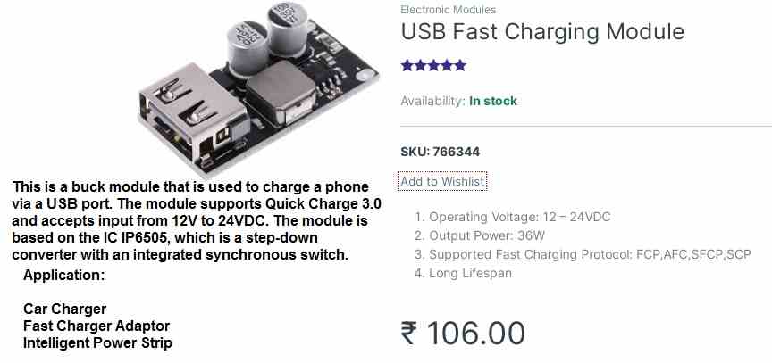
(This contains over and under voltage protection)
The bike battery offers fluctuating voltage (9-15.5V, even lower during cold cranking) and there may also be voltage surges/transients upto 100V.
Hi Vikram,
From its description it seems it can be connected directly with batteries for the buck converter operation. But I am not sure whether the output will be a constant voltage or not, if it is a constant voltage then you can use it to power your Arduino and ESP modules.
sir please how to make simple battery charging level indicator e g 1 led 25 2 led 50 4 led 75 4 led 100 parentage full so how to make it
You can try one of these circuits:
https://www.homemade-circuits.com/3-step-dc-voltage-level-monitor/
how to make simple battery level indicator circuit
charging level use led
Someone keeps using my email to make comments and not their own email. i’d like this to stop before i consider this harassment
I checked my database and found the same email ID as yours used by someone called Chris. I will give his IP address to you so that you can complain against this guy to the cyber crime department.
His IP address is 160.119.108.72
Requesting Your Help: Powering Up Arduino with 12V Motorcycle Battery
Hi,
Hope you are doing well!
I read your article/guide here: https://www.homemade-circuits.com/how-to-design-power-supply-simplest-to/
I am working on a project and was wondering if you could provide some help/support?
I need to power the following projects/components directly via my motorcycle’s 12V Battery (the same battery would be powering all the bike’s electricals)
1. Reverse camera + GPS (Fitted at back of bike, rear facing)
Parts used:
– ESP 32 Cam module
– NEO 6M GPS Module
Application:
To keep an eye on the vehicles coming from the rear end
2. Proximity sensor (Fitted at back of bike, rear facing)
Parts used:
– Arduino Nano
– HC SR04 sensor
– Buzzer
– Red LED
Application:
To detect vehicles coming from the rear end and activate the buzzer and led if vehicle comes in a certain range of distance.
My question:
– What is the safest way to hook up the above 2 circuits with the bike’s battery terminals? As you may know, the bike battery offers fluctuating voltage (9-15.5V, even lower during cold cranking) and there may also be voltage surges/transients upto 100V.
Motive: I want to provide a safe, stable, clean power source to my circuits.
Any help would be appreciated. Thanks in advance.
If there is a danger of 100V spikes then you should try a shunt type regulator circuit such as the following one: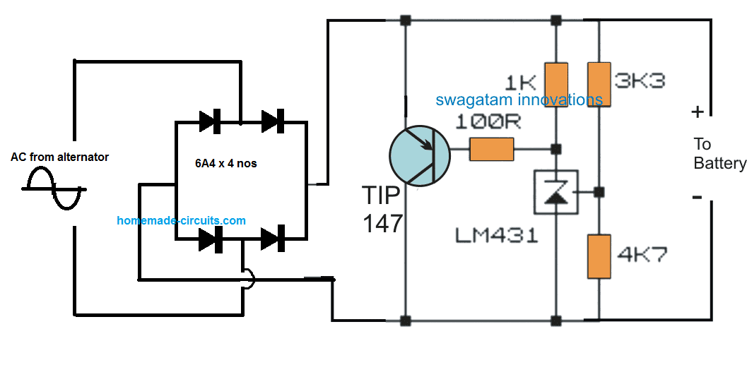
" rel="ugc">
To make the output even more filtered you can add a 2200uF/25 V across the supply rails.
You will have to adjust the 3k3, 4k7 resistor values appropriately so that the desired output voltage can be achieved across the output terminals.
Thanks, will this be suitable for DC?
Currently the image seems to have AC power source.
The alternator output is converted to DC by the rectifier diodes, so the ultimate output to the circuit can be a DC.
Just make sure the maximum DC current is much lower than the transistor’s collector/emitter current handling capacity.
For example the TIP147 has 10 amp max current handling capacity, so the input DC should be less than 5 amps.
Dear Swagatam,
I am interested in your FREE ENERGY FROM INVERTER as you described on you website:
https://www.homemade-circuits.com/free-energy-from-inverter/
Please advise how to replicate your circuit. Or do you sell the inverter described in your article?
Hi Herman,
It was proved by many readers that it is not a free energy, please read the comments under the post.
Sir,
Good evening,
I am trying to connect output from a mono tape recorder to a laptop. An ADC module PCF 8591 is available on a website.
Will it do the job please.
Thanking you for your time,
yours faithfully,
Hi Vishwa,
Sorry, I am not sure about it because I use a computer and have not used a laptop so far!
Hi,
So for the buck converter you built here https://www.homemade-circuits.com/buck-converter-using-arduino/
How can I use the same 9V source to power the Arduino as well?
Thank you,
Miguel
You can see the 12V battery in the first circuit diagram. You can use the same battery voltage to power the Arduino through a 7809 IC
Hello Sir, I’m working on a school project and I’m currently stuck. I’m working on a smart irrigation system using Arduino and a GSM module.
The connection is okay and all the sensors are working already but I’m having problems with programming the GSM module. Currently it can send messages to my phone but when i send a message to the number in the module it doesn’t recieve/display it on the serial monitor.
Pls i need your help on this.
Hello Mike, unfortunately, I am not an Arduino expert, so solving your problem can be difficult for me.
By the way I have a related post in the blog, which you can refer to through the following link:
https://www.homemade-circuits.com/gsm-pump-motor-controller-circuit-using/
Ohh okay
I’ll check the post out
Hey,
I have to build a university project and we haven’t had any electricity classes, but I still somehow build an elevator. I did some research on 555s already and I basically want to make a 555 sr latching circuit that has a LDR as a set input and a IR sensor as a reset. So a golf boll rolls in a box, triggers the light sensor which stays at the bottom, but triggered a DC motor over the 555. As soon as the elevator Box reaches the right level it triggers the IR and resets the 555 latch.
I technically know how to make a 555 sr latch, but I am not sure on how to integrate the 2 sensors 🙁 could you help me? You would literally safe me and I am super curious about electronics and I really want this project to work!
If this really works, you an incredibly amazing person!
Kind regards,
Lennart
You can try the following circuit: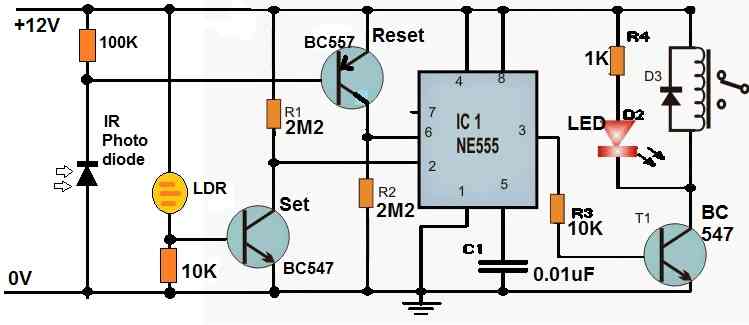
" rel="ugc">
For further questions, please comment under the following post:
https://www.homemade-circuits.com/set-reset-circuit-using-ic-555/
just recently found your blog and upon further reading your post it’s very helpful and I appreciate your work.
I have a project in mind but I am stuck with it, My idea is how can I charge 12VDC 12A 28pcs battery in series connection with balancing charger? Can you help me with it
Thank you, and glad you liked the blog. I have a balance charger circuit, but it is not a tested one. Here is the link for it:
https://www.homemade-circuits.com/lipo-battery-balance-charger-circuit/
Please help me how make simple charger 5v after battery fully so circuit is switch off the input
You can try one of these circuits:
https://www.homemade-circuits.com/usb-automatic-li-ion-battery-charger/
sir used irf 3205 instead of tip 122 pleas
e their is no problem
MOSFET will not work for a 5V circuit, you must use TIP122 or a 5V relay.
I am trying to make a battery charger specifically or li-ion batteries (20700). Configured in a way that, there are 20 cells in series to make one stack (72volts), and 5 of these stacks are in parallel to increase rated current to (15AH). I have made a charger before but its for only single cell in which i used two voltage regulators and Arduino as controller to switch between CC/CV. But facing issues in making it for 72v, input voltage is 220Vac, my desired charger rating is 72Vdc, 12Amps
You can try the last circuit from the following article:
https://www.homemade-circuits.com/make-this-48v-automatic-battery-charger/
Just make sure to use 330 ohm 2 watt for the base resistors of TIP36
The second transistor with TIP36 can be BD140
The BC546 should be also replaced with BD139
use a transformer to step down the 220V to 72V DC
Hello Swagatam,
I would like to make a small vacuum chamber and I would like to use a 12 V relatively cheap diaphragm pump. I know it’s unreliable, but I don’t have much budget to make this. So I would like to have a vacuum on-off switch to automatically switch on & off the diaphragm pump to maintain the vacuum pressure. You know continuous working may damage the pump, which will help to increase the life. I was not able to find a simple solution for vacuum pressure. Hope you can support me on this. I found one DIY product online but no guidelines to build our on and they are selling it in the US only.
Hello Anuraj,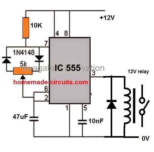
You can perhaps try implementing the following circuit. The PWM pot could be used to adjust the ON/OFF rate of the 555 output relay:
" rel="ugc">
You may have to further experiment by changing the 47uF capacitor until the desired ON/OFF timing is achieved.
Thanks, Swagatam for your quick response.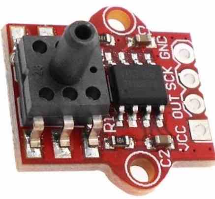
Actually, I don’t have a fundamental knowledge of electronic circuits and IC’s. I love to do DIY this and I learn from that. So google helped me to find out the full form of PMW in IC and it will be great if you can explain it a little bit more considering my limited knowledge.
I have a few doubts.
1. Where I can attach a vacuum pressure sensor to measure the real-time pressure of the vessel and activate the pump accordingly.
2. Normally what type of value is sent from a vacuum sensor? For example resistance / capacitance
" rel="ugc">
3. Can I use the above sensors to measure the vacuum? If yes How can I integrate this into the circuit?
Hope you understand my level of knowledge. Awaiting for your response.
Hi Anuraj,
Frankly, presently I do not have any idea regarding how a vacuum pump and air pressure sensor modules practically work and how these can be implemented in real life. I will have to study them.
You said that you wanted to switch the vacuum pump ON/OFF at a certain interval so that it does not get damaged by a continuous supply, therefore I designed the PWM circuit.
The relay contacts in the circuit can be used to switch your 12V vacuum pump ON/OFF at a given frequency depending on the value of the capacitor and the adjustment of the pot.
PWM stands for pulsed width modulation.
It is the amount of ON time and amount of OFF time that can be produced from pin#3 of the IC 555.
So by adjusting the 5 K pot you can uniformly adjust for how long the relay can be kept ON and for how long the relay can be kept switched OFF. In short, you can vary the On time and OFF time of the relay as per the requirement of the vacuum pump.
Thanks for the response. Basically I want to make a machine with small vacuum chamber. Some more DIY concepts on mind but don’t have much knowledge to make that practical. Anyway thanks for your valuable time.
I think you can try any small 12 V vacuum generator and see how it works. All the best to you.
Can you design a AC to AC SMPS for following conditions:
Input 380-480 VAC
Output 50 VAC output, 50/60hz,
Size: 3500va
The power supply would need to robust enough to be cycled up 300 times per hour, it would be used to replace two transformers used for impulse sealing. It would need to be designed to work with Ropex Sealing controller, model 5011
Also, would need to get it UL listed.
What would it cost to design and phototype?
You can email me directly.
Sorry, SMPS is a very difficult circuit, it won’t be possible for me to design it for you.
Hi I have to generate a code for a three phase two level inverter by using arduino
Hi, I am sorry, my Arduino knowledge is not good enough, so I may not be able to help you with this request.
Hi, do you have a circuit for a 48V under / over voltage alarm. I need a wide range of settings as I will be using it to start a generator on an off grid solar system when batteries get to a preset low level, then stop again when voltage has risen to another preset level
Thanks
Eric
Hi, can you please specify the under and over voltage cut off levels?
Hi Swagman
Thanks for the reply, I would like to be able to have the relay cut in around 39-40Volts, and out again around 46-48 volts.
Thanks
Hi Eric,
You will have to modify the last circuit from the following article to satisfy your requirement.
https://www.homemade-circuits.com/opamp-low-high-battery-charger/
Please comment under the above article, for further discussions regarding the modifications.
Hi Swagman,
I really only want to sense the voltage and operate a relay, this will in turn start a generator, the circuit supplied appears to be an overkill for the job.
I have seen a circuit that i was unable to read due to the poor quality, but it used a LM393 comparator.
Any Ideas
Regards
Eric
Hi Eric,
since you require two cut-off thresholds, therefore you will need an opamp. If you would need a single ON/OFf point then the circuit would be much easier, but even then an op amp would be required.
LM393 is a comparator similar to an op amp and that would also work.
Moreover your operating voltage is 48V while most op amps and compaartors cannot work with that voltage so you will require dropping resistors and zeners.
The circuit suggested by me is the easiest and the most suitable for your application.
Anything simpler than this might not fulfill your requirement correctly.
Dear Sir,
Please tell me if your 2 transistor preamp will be good in a HIFI setup ???
How much does the preamp amplify. I dont need much amplifiation.
C1 an C2 should be of high quality capacitors if used in HIFI setup.
Polystyrene, Polycarbonate or Paper capacitor.
Where should an stepped attenuator be placed, mayby before C2 ?
How is C2 polarized, is black plus ?
Best regard/Yours sincerelly.
Hi David, can you please ask this question under the same article which you are referring to, so that I can see the diagram which are you are referring to.
I found it under the 5 simple preamplifier circuits explained.
1) Preamplifier using two Transistors
yes the 2 transistor preamp will be good in a HIFI setup.
https://www.homemade-circuits.com/small-amplifier-circuit/
C1 can be any ordinary disc ceramic capacitor, C2 can be an electrolytic capacitor. Black is minus, white is plus.
Neither ceramic or electrolytic capacitors are good in the signal way in a HIFI setup.
They sound bad.
Use only polycarbonate, polystyrene or paper capacitors.
Or if the capacitors are large they should be paralelled with a good capacitor like above mentioned.
Hi there Swagatam , how can the sinewave driver circuit be connected to a transformer with no center tap connections only single 12 v input
Regards
Andrew
Hi Andrew, You will need a full bridge driver circuit for that, with a specialized driver IC. This IC will need to be fed with a sine wave signal input
Hi,
I have a circuit question regarding upgrading an internal circuit board for rc truck and wanted best possible for my project. I am trying to make rc truck go quicker, agile, further distance, etc. Can you give me any recommendations for my project? Would greatly appreciate any suggestions for my project and have a great weekend.
Thanks,
Bill Miller
Hi, Although I do not have a sophisticated RC truck circuit, I have a similar looking circuit which operates a trolley using remote control. You can find it in the below given link. Hope this helps.
https://www.homemade-circuits.com/remote-controlled-trolley-circuit/
Hi Swagatam,
Thanks for the respond on my question regarding my project and look at the website and your suggestion. I really appreciate your assistance and have a great weekend.
Thanks,
Bill Miller
It’s my pleasure Bill,
You too have a great weekend.
Thanks Swagatam for the assistance and best of luck with your future projects as well.
Thanks,
Bill Miller
No problem Bill, all the best to you!
I have used a Mosfet controlled fan speed control circuit IRF 740 Mosfet driver with a PWM Driven Optocoupler I faced problem in decreasing the fan speed pl suggest rectification
When I increase the duty cycle of PWM, it successfully increases fan speed accordingly
When I decrease the PWM duty cycle slowly, fan still runs at same speed, and doesn’t slow down
When I turn off the PWM, fan stops with a sudden jerk, and my MOSFET blows off after becoming too hot
The same circuit works well for dimming of resistive loads like incandescent bulb
So I wanted to know, what modifications do I need to make in my circuit, to safely handle the decrease in fan speed?
I want to make sure that after operating the fan at 100%, even if I turn off the PWM suddenly, the fan should still stop gradually and not with a jerk.
Is your motor a DC motor?
Which circuit did you use for controlling the speed of your motor?
I need 150khz mosfet switching driver IC selection for 40 amps 600v for inductive load(to drive 1.5 hp 240 v ac water pump motor )
you are requested to suggest the better operating frequency
What is the purpose of the circuit? Is it for controlling the motor speed?
i am planning to control the power transfer to the single phase motor water pump (1.5 HP=1.12 Kw) with out changing the frequency/ speed
Please suggest the best switching speed, suitable driver for 40n60 Mosfet 40 Amps 600v to overcome switching problems and avoid Rf interference effects
i selected the Mosfet ratings as per below calculations
Vrms 230 V , Vpk= 1.414*230= 325 v, overload factor 150% 325*2
=487v, i have selected 600 v rating Mosfet
Motor Current= 1.12kw/230v/.85(PF)=5.71 A
Motor starting Peak currents Max 5 Times of rated current
5.71*5=28.6A Rms
Staring Current Peak Value 1.414*28.6= 40.4 A
Here non continuous Staring Currents range Covered Design Over rating Margin
so I have selected 40 Amps rating Mosfet
I have a 2005 Polaris UTV. The voltage regulator is incorporated into the ECM/PDM and has failed. Could I bypass the ecm and install an external voltage reg?
Sorry, I am not sure whether the vehicle system would allow this or not? I can provide you the circuit idea of the regulator but I am not sure how the vehicle electronics would react to it?
That would be great.
Thank You
OK, could you please tell what is the maximum voltage output from the UTV alternator? And at what voltage level would you want the regulator to control the output?
65 v at 5000rpm. I think around 14v would be sufficient
You can try the following concept: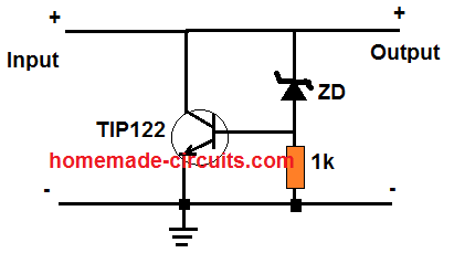
" rel="ugc">
Feed the input to the circuit through a bridge rectifier.
TIP122 could be replaced with a TIP35 for more current handling.
The zener diode could be replaced with the 14V zener diode.
circuit with IC1 LM 567 can pin 8 activate a relay. ?
which capacitor do i need to change value? to control latch time on/off.
goal for this project is arm and disarm unit remotely and when a Britch is made send signal to a smart phone.
do you think that kind of circuit is possible?
Can you please specify the exact schematic you are referring to? I don’t seem to find the relevant circuit related to our discussion.
Hello from Italy!
I’d need a small circuit to regulate the current for a LED strip, to be installed on my motorcycle.
I need to limit the current ’cause the strip have to stay cool and not overheat.
I tried a small LM338 circuit but it fails (and become VERY hot) and someone on reddit told me that it is ’cause there’s not enough DeltaV between the source (the ~13V of the bike) and the 12V required by the LEDs.
Do you have a working solution?
Hello Parduz,
If LM338 circuit is heating up for you, then you can try a MOSFET or a BJT based regulator, as explained in the following article:
2 Best Current Limiter Circuits Explained
Let me know if you have any further questions.
hello Swagatam
i have a gas fire it is controlled by Magiglo VAL0764 Remote Control Handset & Receiver
i think ULTRASONIC TRANSDUCER 40KHZ is failing in the receiver it makes a jerking clicking sound
can i replace it with any type ULTRASONIC TRANSDUCER 40KHZ
don’t know anything about electronics but solder
could upload a picture where ?
thanks, billy
Hello Billy, according to me all types ultrasonic transducers should be able to detect 40 kHz frequency, so you can use any type of transducer.
hi Swagatam
thanks for the reply
in your opinion do you think it is a 70% percent chance it is the ULTRASONIC TRANSDUCER 40KHZ that’s causing the problem
it says to but in four 1.5 v batteries into the receiver = 6v did that and it jerks
I replace them with 4 bad batteries = about 4.5v and it works great
what do you think
thanks, billy
Hi Billy,
If the jerking stops with the use a lower 4.5V, then it could be an over voltage issue for sure. It is not a transducer issue.
In that case you should stick with 4.5V or maybe a 5V battery, if a 5V is available.
Hello Swagatam,
I am looking for an circiut to control 220 Volt Phase for an Electric Heather with a Fan using 220 Volt.
Just want a phase shift circuit for this.
This circuit must have all the components with the part number.
I thank you for this,
Greatz,
Haiwan
Hello Haiwan, You can try one of the concepts explained in the following article:
220V Light Dimmer and Ceiling fan Regulator Circuit [Using Triac and Diac]
Thanks Swagatam, i will check this and if i have any porblems I will contact you.
gr
haiwan
Hi engineer. I have a good 220V AC-28V AC voltage transformer. I would like to use it to build a stabilized power supply of which I have a kit. However, this needs to receive an in a voltage of 26 V AC. What is the best way to achieve this? Thank you
Hi Rosario, your 28 V AC cannot be reduced to 26 VAC, so I am afraid this transformer cannot used with your kit.
Instead you can use a simple LM338 based regulator circuit to build a stabilized power supply.
Hello
Like to know,what is the difference between mic pre-amp and guitar pre-amp or audio pre-amp
like to build one,but not sure what to do…………..thanks.
Hi, all of them are similar with their basic function, however their preamplification specification can be slightly different depending on the application.
Hello;
Thanks for the reply,you said the specification can be slightly different depending on the application
but in what way can be slightly different depending on the applications,,,,,,,,,,,thanks.
Hi, the sensitivity, amplification and gain may differ slightly.
My name is vinu. I am a grade 7 student. I need a sensor which can deduct the flow of saline in an iv line. It should not touch the liquid probably a light sensor.
Hello Vinu,
You can probably do it by sticking a tiny solar cell on one side of the IV line, and placing an LED lamp on the other side. The soar cell then can be connected with the milli-voltmeter to check the turbidity of the saline solution and detect the saline level.
Sir I Need Help Me Microcontrol Circuit Use Timer 555 Or Cd4017 On 20minute Atleast Delay 5 In Off ,..! Instead Of Arduino Or Cd 4060 Circuit
I want to interface the following Current Transformer with an ESP32 (3.3V system).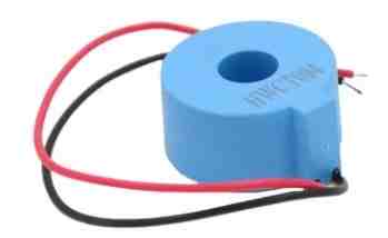
" rel="ugc">
Can you suggest me a suitable circuit (with values of the components) required for it?
The transformer gives current output in the range of 0-50 mA for loads up to 50A. But ESP32 can sense only voltage. So, we need to convert that current to voltage (in a range which is acceptable by the ESP32)
Thanks in advance.
ESP32 is a low-cost, low-power system on a chip (SoC) series with Wi-Fi & dual-mode Bluetooth capabilities!
So I can’t figure out how you want to connect a current transformer with it.
Please explain in details the sense pinouts of the ESP32 where you would like to integrate the current transformer and also the purpose.
Swagatam thank you so much for your reply. What I need basically is a Current to Voltage converter which will convert current in the range of 0-50 mA to voltage in the range of 0-3.3V. I would then connect the Voltage output to the ADC pin of the ESP32 and measure the voltage to find out the current flowing through the transformer.
Thank you Biswajit,
You can simply do it by connecting a low value resistor (shunt resistor) across the secondary output wires of the current transformer. The resistor will convert the current into a voltage drop across itself. You can start with a 50 ohm resistor and check whether it produces a 3.3 V range of voltage across it or not. You can adjust the resistor value accordingly until the correct range of 3.3 V is achieved.
I also have a related article in this blog, you can check it out here:
Monitoring 220V AC Load Current using Current Transformer [Circuit Diagram]
I am trying to make a 110v AC to 110V DC cicuit. When I place a bridge rectifier across the mains, the voltage increases to 169V DC. I installed a 470uf capacitor but the voltage remains high. I need to operate a controller at 110v DC approximately 2 amps. Do you have a circuit I can use for this purpose? Thank you, Rich
I think you can try the second circuit from the following article:
https://www.homemade-circuits.com/0-300v-variable-voltage-current/
The R2 resistor controls the output current. You can tweak the value using the following formula:
R2 = 0.6 / max output current
how to make simple programmable timer setup with cellphone and digital display
sir,
I have battery and charging power plant, the capacity of battery is 48 v. For this i want to make circuit that it shows the mains ac supply failed and low voltage indicator .low voltage range will be below 47 volt.
sir kindly help.
Ajeet, for the mains failure indicator you can try the following circuit:
" rel="ugc">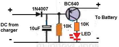
for low battery indication you can refer to the following article:
Low Battery Indicator Circuit Using Two Transistors Only
sir how to make security alarm
Hi Swagatam,
Can you please create a post to share a circuit for controlling AC Mains Fan using an Arduino. It would be best if the input to the Arduino is taken from an TSOP1738 or similar infrared sensor. I have see some similar circuits on the internet, they are confusing because they do not elaborate the usage of various components in the circuit. For example, most of the circuits use a 4N35 Optocoupler and there is a zero cross detection stage. Can you please explain/confirm, if this stage is required, when I power my Arduino with a dedicated DC power supply. I see most of these circuits are trying to run the Arduino from Mains power, but when you share your circuit, please keep the Arduino power supply part simple/separate and from a DC source.
Hi Prithwiraj,
My Arduino knowledge is not good, so creating any Arduino based project can be difficult for me. All the Arduino based projects posted in this site were written by another author.
I have a seven foot DIY outdoor Menorah made with nine 99¢ store flickering LED hollow pillar candles each powered by a 3v CR2032 coin battery (no resistor). Every 24 hours I manually replace the old batteries and light the next LED each of eight nights and would like to replace them with a very simple timing circuit or controller. You activate the Menorah and the center and first LED candles light, followed every 24 hours by the next candle over eight days. They all stay lit until you switch it off.
I would like to automate this with a very simple and cheap circuit I can share with kids as a DIY project. This could be a popular project for some of your readers and I would be happy to pay for your time. I can solder and can read a schematic but other then real basics I am not an electronics guy. I am completely open to any suggestions, but it seems there are a few options based on the design of the Menorah.
First one circuit board with wires going to each LED. Second, the plastic candles are hollow so one 24 hour circuit board in each candle could power it’s LED and send a wired trigger signal to start the 24 hour timer circuit in the next candle etc. Third, if not too expensive, individual circuits in each candle that activate each LED in 2,3,4,5,6,7 and eight days that I turn on at the beginning of the cycle. I would like to use a small AC to DC transformer to power this, but there is enough space in each candle for double A or C batteries if needed. I don’t think this needs a relay because the flickering 3v LEDs currently can go over 24 hours on a single button battery so the power draw is maybe 50ma?
It is absolutely not needed but if not complicated – it would be nice to resent the LEDs to a certain day in case something goes wrong in the middle of the sequence – however I would be overjoyed just to get this automated at even the lowest level! THANKS ALL!
I think I already have a similar looking design in this blog. Separate circuits won’t be required for the individual candles, a single circuit will be able to handle the entire sequence of 8.
https://www.homemade-circuits.com/digital-christmas-candle-light-circuit/
Swagatam – this looks great – thanks so much for your help!
My pleasure Tom, glad to help!
Hi Swagatam, Is this your first name or nickname? It is a pretty cool name meaning “Welcome” in Sanskrit! I think I found a minor mistake reversing pins 1 and 5 outputs in your schematic which would light those LEDs out of sequence. Also – any suggestions for the values of the resistors and capacitor in 4060 – I don’t know where to start with that! I adjusted your 25 light circuit to 7 for a Menorah – how can I post a JPEG for you to take a look?
Thank you Tom, it is my first name! That’s right, it means welcome in Hindi and sanskrit
Can you please elaborate on what you meant by “I found a minor mistake reversing pins 1 and 5 outputs in your schematic….”
Regarding selecting the 4060 timing components, I have explained it in the following article, under the heading: “Calculating RC Timing Components”. Please check it and let me know if you have any further questions
https://www.homemade-circuits.com/how-to-make-simple-programmable-timer/
HI Swagatam – Sorry – I should have said “reversing the listed sequence of pin 1 with 10” (NOT reversing pins 1 and 5 outputs). I found a pinout of the 4017 IC at eleccircuit.com and it showed the following output. Out 0 = pin 3 / Out 1 = pin2 / Out 2 = pin 4 / Out 3 = pin 7 / Out 4 = pin 10 / Out 5 = pin 1 / Out 6 = pin 5 / Out 7 = pin 6. In your schematic you have the pins listed in this order (sequence?) 3, 2, 4, 7, 1, 10, 5, 6. So it could be someone’s typo reversing 1 and 10. Also did I get it right that 4017 pin 13 would go to pin 6? I have an adjusted schematic for you to check if you tell me how to send it to you.
Thank you Tom, for the clarification and for pointing out the typo! I have now corrected the mistakes in the diagram and updated it appropriately. You can check it out.
I have explained the 4017 pinouts elaborately in the following article, which you may refer to for more info on the same:
https://www.homemade-circuits.com/how-to-understand-ic-4017-pin-outs/
Pin#13 of IC1 would go to Pin#1 of IC3 according to the corrected diagram, since 25 LEDs are involved.
For submitting your diagram you can upload it to any “free image hosting site online” or to your Google drive account and send me the link here, I will check it out and provide my feedback to you.
Swagatam, This is for a Menorah so there are only 7 lights that need to be sequentially lit after the circuit starts (the center and first LEDs are wired direct to the power source so only LEDs 2 through 8 need to be part of the 24 hour sequentially lit LEDS. Here is a link to what I thought the circuit would look like for the 7 24 hours LEDs: https://drive.google.com/file/d/1WvRvEn1pk6-8MAZw9q_NSox6XgirOieT/view?usp=sharing Please change if needed.
Hi Tom, the PNP transistor will not be required in this design, it can be removed. And the pin1 and pin10 must be swapped with each other. Rest everything looks perfect to me.
Here is the Dollar Store Menorah up tonight – operating with manually inserted coin batteries:
" rel="ugc">
Here is your 25 LED circuit I adjusted for 7 Menorah LEDS – please edit if needed so I can try to use your circuit this year:
https://drive.google.com/file/d/1WvRvEn1pk6-8MAZw9q_NSox6XgirOieT/view?usp=sharing
It looks very nice indeed, thanks for updating the pics.
Hi, I think I have the final circuit with all of your changes – could you give it one more look?
I did swap pins 1 and 10 but doesn’t that bring us back out of sequence on outputs 4 and 5 (Out 4 = pin 10 / Out 5 = pin 1)? I also adjusted the voltage to match the 9 volt battery. Thanks for your final OK!
https://drive.google.com/file/d/1eQqCPcw2VSJPevUIDGSXehgizmFP1VNk/view?usp=sharing
Hi, It seems you missed the LEDs…the LEDs should be in series with each of the SCR anodes, and pin1 and pin10 are not in the correct sequence. Remaining circuit looks OK to me.
For the pinout sequence please refer to the following datasheet:
https://www.ti.com/lit/ds/symlink/cd4017b.pdf?ts=1671448205885&ref_url=https%253A%252F%252Fwww.google.com%252F
Hi Swagatam – thanks for your patience and the info this should be my last post on the LED Menorah.
I have never done this before so most of the info you sent is WAY over my head. In fact the Silicon Controlled Rectifier was not mentioned in your instructions so I took it out because I mistook it for a second LED! It is back and I now understand its function is to power its LED once the timer output pulse(?) closes the gate and power flows through the LED connection. HOWEVER I still have no idea what to do with IC 4017 pin 13 – “Clock Enable.” I connected it to pin 6 because in your original 25 LED circuit it was connected to the output following the last Christmas (25th) LED. On the Menorah, pin 6 would be the output following the last (7th) LED to be lit. PLEASE let me know where it goes – I am completely lost on that final point. Here is an updated schematic:
https://drive.google.com/file/d/10E2Ba3qfpNAFf_XmwsiMwpW1i1esBFqt/view?usp=sharing
INTERESTING QUESTION ONE: The existing Menorah LEDs are each powered by a tiny CR2032 3v Coin Cell Battery without anything else. I understand that the two ICs and components are needed for the complicated timer function – but what happens at the IC 4017 activated outputs? Is there a “pulse” or an “electrical flow”? If the activated output is continuous – couldn’t the 80ma LEDs connect direct to the pin and then to ground if the power supply was lowered to 3V (which is the lowest voltage range for both ICs)?
INTERESTING QUESTION TWO: I have read that IC timer circuits are inaccurate over a few hours because the capacitor used leaks amperage throwing the count off. Is that true? If so, is there a way to correct this or will a higher quality capacitor solve this?
No Problem Tom, I am always happy to help!
Yes SCRs are required across the outputs so that they can latch the LEDs permanently ON, as soon as they are switched ON.
Pin#13 requires a ground connection for enabling the 4017 output sequence to carry on its sequential movement. If the pin#13 is connected to the positive line, the sequencing process instantly freezes and stops.
In your circuit if you connect pin#13 to ground, then the 4017 output sequencing would go on progressing until it reaches the last pinout pin#11 and the then the whole sequencing would reset back to pin#3.
Connecting pin#13 to the pinout immediately after the last LED pinout causes pin#13 to go HIGH, through the positive pulse received from pin#6. This instantly “freezes” the whole sequencing function and it remains “frozen” in this position until power is switched ON/OFF or pin#15 is momentarily connected to the positive line.
However, I think pin#13 connection is not relevant to your application, because the SCRs would be latching the LEDs permanently ON, so even if the 4017 IC is reset if won’t affect the LED illumination.
I don’t think coin cells would be able to power the ICs and the LEDs together for many days….they would hardly last for maybe 1 day or so.
1) The outputs from the 4017 switches ON and then OFF as the sequence progresses from one pinout to the next. However, since SCRs are used the LEDs would remain permanently switch oN as soon as the relevant SCRs are turned ON. That is exactly why SCRs are used.
2) Yes, 4060 timer can drift away from the set timing, however in our circuit the use of diode at pin#12 of the IC 4060 ensures that the IC 4060 is reset each time a 24 hour cycle is completed which enables its timing capacitor to discharge fully and start afresh. This helps to reduce the time discrepancy to a great extent.
Yes, a tantalum capacitor for C1 will help to enhance the timing accuracy.
Other alternative is to use a crystal with the IC, but I do not have this circuit with me right now.
Dear Swagatam, “Pin 13 to Ground” – Thank You, Thank You, Thank You and Merry Pancha Ganapati! You certainly are a giving person, sharing your incredible knowledge and patience with an electronics newbie! Your detailed explanation really helped me understand your circuit! Please check the email address used to contact me. if you can’t do that email me from an address you can access for my thank you.
Its my pleasure Tom! I am glad I could help!
You can get in touch with me on hitman2008 @ live.in
Hi,
Do you have a template for the PC board used in the 50m dog “trainer”?
I am building something similar but my knowledge is limited and designing PC boards is something I know nothing about, besides I would be inventing the wheel.
Thank you
Hi, I do not have the PCB layout, but I do have the circuit diagram. The PCB layout can be obtained from any online professional in this field.
hi sir please I have ups transformer so give me circuit diagram about 1kwatt simple circuit with using CD 4017 or SG 3524
Hi Abdul, do you want to make a square wave inverter or a sinewave, and what is voltage rating of your transformer?
OK show me how make it
I asked you about your requirement specifications in the previous comment!
yes I mean me I went make square wave or sinewave inverter or pure is ok
You can try the first schematic from the following article:
https://www.homemade-circuits.com/modified-sine-wave-inverter-circuit-2/
Hi,
I am regular follower of your website. You are absolutely genius in electronics and the way you represent and explain the technicals here.
I am new to electronics and do little projects my own.
I need help for designing surge protection circuit of 10KVA for led street light having MOV and fuse resister. I don’t want to use gas discharge tubes.please help provide design file.
Thanks.
Thank you Mukesh for your kind words, and Glad you liked my website!
Before I try to provide a solution I wanted to know how is your LED lamp powered? I guess it is powered from 220 V mains AC and not through a battery system.
Kindly let me know about this?
Yes its from AC 220v main. Wattage of street light are from 24W to 110W.
OK, and what is used for the power supply, is it a transformer or an SMPS. If it is an SMPS then it may already have an NTC and MOV based surge protection system in-built?
no, its only for surge protection. it will be connected to LED driver of street light or flood light.
You can try the last two circuits from the following article:
https://www.homemade-circuits.com/how-to-make-simple-ac-mains-surge/
sir how are you so i have 6.68v 0 6.68 ups transformer how to bult simple inverter circuit
Hello Abdulkarim, You can use it to build any inverter circuit from the following article.
7 Simple Inverter Circuits you can Build at Home
Sir:
I am a retired older person just getting back into electronics. Having grown up designing around tubes/valves I am very lost in the modern IC world.
Is there a reference source that will point out which IC family to begin research, i.e.: datasheets, etc., for a particular application or block in more complex applications?
Thank you for your time.
Gary
Thank you Sir, I appreciate your interest and glad you are getting back to electronics.
I would recommend exploring the IC 555 which is an universal electronic workhorse device with unlimited applications.
Below are the couple of links which you can explore for learning about the IC 555
https://www.homemade-circuits.com/timer-ic-555-explained/
https://www.homemade-circuits.com/category/555-ic-circuits/
Let me know if you have any further queries.
sir how to make mobile phone charger using 3.7volt
You will need a boost converter to convert the 3.7 V to 5 V and then you can use it charge your mobile phone.
How can make it
simply
You can try the second circuit from the following link. Remove C3, D2, D3 from the circit since you won’t need the -5V supply.
https://www.homemade-circuits.com/how-to-make-simple-boost-converter-circuits/
Hello sir,
I came across this load cell (https://www.homemade-circuits.com/weighing-scale-circuit-using-load-cell-and-arduino/) project of yours that I am interested to mimic and implement.
I want to incorporate a “milligram” sensitive measurement in the range of the weighing. Is that possible to do so using this setup?
Hoping for your help and guidance!
Thanks and Regards,
Ansari
Hello Ansari,
You can surely try the concept, however since I am not good with Arduino coding, won’t be able to suggest any modifications in the code for your specific application. You may perhaps try asking this question in an Arduino forum online, somebody might be able to help you out.
good after noon sir
please
how to make simple switch like
1 clap switch on and off
2 or using sound switch on and off
Hello Abdulkarim,
Please use the search box and search for “clap switch” and “sound activated switch” you will be able to find them easily in this blog.
Hi there,
I am in trouble to build or buy a 2.4Gz transmitter and receivers for the model raailway I’m building The scale is “I” (32mm to 1 m )At the moment, an electro railcar is built . Some more locomotive are planed to be built. So, from the transmitter I must be able to send commands by radio to these various rail workers , being understood that the commands are the same for any engine : they should be : 4 for speed: very slow, slow , regular , full speed . 1 for “uncoupling” ,1 for “stop” . all are get onboard the engine with relays working with 12 v DC (battries are on the engine . There is also an other battery with 3.6 V for the receiver. An other point is the antenna: all the stuff is inside the cabin which is made of iron sheet . The antenna should be on the roof of the engine . Ho to build it ? I am very sorry to have made a very long description of my project . Thanks a lot for your help . Regards . Guy MARCHAND .
Good day
I use a 50A 12V DC battery charger to charge my backup system. The charger gets very hot during the charging cycle. I want to install two 230V AC cooling fans that automatically comes on and off for the charging cycle. There is a 5mm LED that indicates when it is charging. I thought to use that to switch the fans with a relay, but I do not know where to start. Please help me with information on how to do it.
Thank you
Petrus.
Hi, I think a relay may not be required, you can connect the fan directly to a transistor driver circuit as shown in the following figure: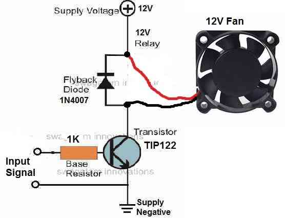
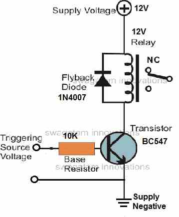
" rel="ugc">
If you think a relay driver would be better in that case you could try implementing the following design
" rel="ugc">
Let me know if you any further doubts.
Hi, the fans are 230V AC, so the fan circuit must be isolated from the trigger circuit – that why I thought a relay will do the trick. I just need to switch the relay from an existing LED that probably runs at 2V DC.
Thanks.
OK, no problem, then you can use the relay version of the circuit:
" rel="ugc">
I hope you know how to configure the contacts of the relay to operate the fan via 230 V AC.
sir please how can I make micro controller using some minutes 118 minutes off 2 minutes on 118 off 2 minutes at least 118 off 2 minutes on how can I do it sir
Hello Abdulkarim, you can try modifying the following concept to get the intended results:
https://www.homemade-circuits.com/arduino-2-step-programmable-timer-circuit/
Dear all,
I have a mosquito killer lamp that it doesn’t work properly.
I changed the battery and now the light appears works fine but the electric mesh doesn’t work.
I’d like to understand the circuits of my device in order to learn, with a real condition, something new when I try to repair it.
I found a problem with the electrolitic capacitor (swallen on the top) and the area close the a transisor (BT169D) was burned.
I prepared some photos and other informations regarding the PCB but I don’t know if someone wants to help me to, with some explenation
on the circuit. Let me know if it is possible to send more details. All the best
Claudio
BT169 is an SCR not a transistor, so it is strange why an SCR used in your circuit? I have never seen an SCR in a mosquito swatter bat so far. You can try replacing the swollen capacitor and the SCR both and check if that helps to restore the working of the bat.
Dear sir,
thanks for your reply; I changed the BT196D thyristor and I checked that tha lamp works and also the tension is around 780V DC on the wires to the mesh…
I’m quite fear fair to create a short and test the grid, can you suggest the section of the wire to do this? (clearly I’ll do it with max attention so)
I prepared some photos and documentation of the pcb, I tried also to skect a schematic but I need an help to understand how it works.
There is a possibility to have an help with theory of my device?
Thanks in advance.
Claudio
Hi Claudio,
That sounds good! you can upload the schematic to any free online image hosting site and provide me the link here, I will check it out and if possible try to explain it to you.
Great,
this is the link to download some photos and info:
https://we.tl/t-6WmwrrqZR5
Thanks in advance.
Claudio
I tried to understand the stages but unfortunately I couldn’t, since the pen drawing is not so clear and the schematic has too many interconnected components. However, I guess you can try shorting HV1 and HV2 points since these are the points that are supposed to go the mesh. Moreover there’s no other way to confirm whether the bat is working or not.
Thanks sir,
I have done the short test on HV side of PCB, with a powerful spark, it is ok.
I controlled also the mesh net; on one side the wire makes many round from the bottom to the top of the lamp and finish without interrupted area;
at the same time, on the other wire, it makes many round like the other one, alternating; aslo this circuits, with continuity and without particular dent, I controlled the continuity (START-END) on each circuit and it appears ok. Probably the device is ok, replacing the burned thristor, but
I’d like to learn much better the circuit.
In your opinion, if I prepare a better drawing, instead of the previous one you can produce a schematic drawing in order to explain the function?
Thanks a lot for your patience.
Hello Claudio,
I appreciate your interest, however the circuit which you have shown is quite big and will require a lot of time to understand and explain, which can be difficult for me due to lack of time. I hope you will understand and bear with me.
Don’t worry,
I appreciate your answers.
All the best.
Claudio
Thank you for your understanding, appreciate it!
Hey!
Have a question about my project for my grandson Gocart.Pwm dcmotor 36 volt brushless.
Designing an own control, thinking with 2 1000 watt motors connected in parallel.
The control basically consists of LM339. mos driver TC4427. power stage 6 pcs parallel connected IRFP3206 gate resistor 33 ohms on each mosfet. 2 pcs SCHOTTY MBR30C100.
current limiting resistor of 1.5 mohm I also thought via which the LM339 can also control. So that the current does not increase too much.
What I’m wondering about is that no filters (suppression circuits) are needed over the mosfets and the motors.
For example, DC motors generate voltage themselves when the speed is reduced.
If you are interested. How do I send a picture of my clutch
Thank you for your reply
Best regards Goran
The back Emf from the motor can be generally suppressed using capacitor and diode connected parallel to the motor coil. If you already have schottky diodes connected parallel to the motor coil, then you do not have to worry much. You can further add a 3uF/400V PPC capacitor in parallel for added suppression.,
Hi! Will test it. Thanks
Hello Swagatam.
I trust that you are keeping healthy and fit.
I am sorry to bother you again but I wonder if you can help me.
I have searched the internet for a circuit for a circuit that will effectively test a TL081 single JFET op amp.
I have found several circuits, some with one led and some with two leds to show if the op amp is working. I have built a few of these test circuits but here is my problem. I have a variable power supply with current limiting as well. I built this PS from a Smartkit 1138 0-30 volt 3 amp kit several years ago and it has served me well. I recently added a digital voltmeter/ammeter to it and it stopped working. (my fault) So I removed the meter and it still did not work. So I tested the four transistors and replaced two of them and it still did not work. The board has three TL081 op amps so I tried building a test circuit and the led flashes with all three amps. So I built one with two leds and only one led flashes instead of the two alternating like a flip flop. So I bought three new TL081’s and fitted them and it still does not work. So I put the new op amps in my test circuit and again only one led flashes.
So now I am looking for a test circuit the definitively tells me whether the op amp is good or bad. My power supply gives me no voltage output and the current limit led stays on all the time. I have tested all the diodes and resistors and I cannot find the problem. If you can help me with this I would be very grateful as I am lost without my power supply and a new kit is no longer available.
Thank you and best regards.
Patrick Chapman
Hello Patrick,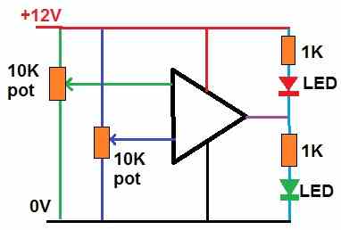
You can try the following basic op amp tester circuit:
" rel="ugc">
Moving the either pots up and down should cause the LEDs to change their status.
However I would rather suggest you to build a new power supply circuit. A good power supply can be built even without op amps, and simply by using ICs like LM338
Hello Swagatam,
Thank you for the op amp test circuit. I will put that onto a bread board now and try it out. I did do a search on your site for an op amp test circuit but nothing came up so thanks for finding that for me. Your assistance is always so helpful.
I will look into building a new power supply if I can’t repair this one.
Keep well,
Best regards
Patrick.
No problem at all, hope you succeed with the project….wish you all the best!
Hello Swagatam,
I have breadboarded your op amp tester circuit and it works great so thank you for that. I have tested all of my TL081 amps and they all test out good so it seems that that is not where my problem is.
I have looked at a few circuits using an LM338 voltage rectifier and they are all very basic compared to my CC – CV power supply so I am going to hang in there for a while and see if I can’t restore my power supply. I can set the current output to as low as 200ma at any voltage up to 31 and this has proved so useful over the years that I going to try for a while to fix it.
Thanks again for all your help and suggestions so far. You are such a great help to us electronic hobbyists.
Keep well
Best regards
Patrick
You are welcome Patrick,
Glad the circuit worked for you! The LM338 can be also configured for obtaining any desired CC, CV.
Nevertheless, I hope you are able to restore your existing power supply soon.
Hi Swagatam,
Your help and advice with my electronics fumbling has been invaluable and I sincerely hope that you are around for a long time to come to continue to help us electronic hobbyist’s.
On Aliexpress I found a 0-30 volt 3 amp power supply kit which looks almost identical to my Smartkit 1138 kit so I have ordered two of them with a view to replacing mine if I can’t repair it. There are also some good threads out there to help with de-bugging it and improvements if you have a problem with it. There is also a couple of youtube video’s on assembly and testing so it does seem to work alright.
So at least I now have a plan moving forward and I am hoping that it all turns out well.
So thanks again and stay well.
Best regards
Patrick
Thank you Patrick,
I am always happy to help!
That sounds great! I truly hope you are able to configure and test the available kit correctly, and your requirement is fulfilled soon.
please give me your WhatsApp number so that me send picture of construction
You can upload the pictures to any free image hosting site and give me the links here, I will check it.
sir I used 2k resistor instead 1k they has problem
Please show me the circuit, only then I can say!
sir please I did not have this step up transformer me can having radio 5 terminal transformer so how can I make simple
220v an bigger higher power an frequency
The output power will depend on the power of the transformer. So if the power of the transformer is less then the output will be also less. The output voltage and power depends on the voltage and power specifications of the transformer.
sir how are you I can construction modified sine wave inverter but I did not have diode 1n4148 I can use 1n4007 remember I used radio transformer so the output voltage is 36v so how to increase the power voltage and frequency thanks you
Hello abdulkarim,
1N4007 can be used instead of 1N4148. You must use a standard 220V step-down transformer for an inverter, a radio output transformer will produce very low output power.
Hello,
I have 60plus Meanwell SMPS to repair, could you help by taking this job under you. Please share your contact details and in which City you based in?
Hi,
I am so sorry, I won’t be able to take this job since I am already too busy with other job assignments.
Hallo Swagatam, my vivid compliments for your work and your availability.
Like many your readers I’m an electronic hobbyst and my field of interest is the resonance. Since a long time I’m looking for a circuit based on the 555 chip (CMOS) to produce a near-perfect square wave with a fixed 50% duty cicle but, unfortunately, there are none out there able to satisfy my needs so I thought of you.
These are the wanted characteristics:
– ultra-low power-draw (that’s why I specified above the “CMOS”), preferably in the order of the micro-amps for the oscillation circuit per se;
– able to generate a PWM with a variable output current (5-100 mA) and a variable frequency (20kHz-250kHz);
– the output PWM has to be totally insulated from the 555 (no back-emf spikes allowed to be returned to the chip) OR the output must have a very high impedance
– the input voltage of the circuit should stay in the range of 5-15 and the output voltage has to match the input voltage.
That’s it.
Of course I tried some configurations by myself, getting inspired by many schematics on the web so, for example, to insulate the 555’s pin 3 (output pin) from the external resonating circuit (a stupid LC couple), I put a pulse transformer (those micro guys used in some arrangements between the mosfet’s drivers and the mosfets) but this resulted in a big mess of unwanted harmonics so I gave up.
I have a friend, in Tamil (India) which is a retired electronic engineer and he wasn’t able to figure out how to solve the back-emf spikes without affect the resonance of the external LC (which has to remain “stable” and produce as high voltage as possible) and avoid the return of the high voltage to the 555 chip.
One curious thing: my arbitrary frequency generator (a cheap chinese box full of functions) is able to withstand even to 2 kilovolts of back-emf spikes without any issue (wtf…)
Any suggestion will be much appreciated.
If needed, for further details for example, feel free to come in contact directly through by the provided email address.
Thank you so much in advance and keep up the good job!
Fabrizio
Thank you Fabrizio,
You can perhaps try the following design for the 555 PWM generator. The frequency is obviously determined by the values of R1, R2, and C3.
You can a see zener diode across the supply lines, you can beef up this zener diode with capacitors ranging from 0.1uF to 1000uF. These will probably quite enough to ensure that spikes are appropriately neutralized before they can enter the IC 555.
And yes instead of 555 you must use a CMOS version 7555.
" rel="ugc">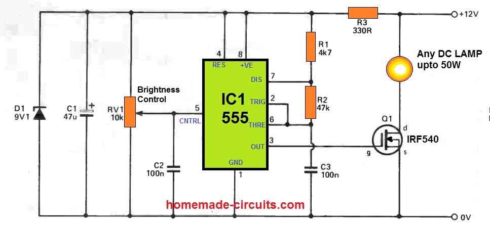
Hallo SWAGATAM and thank you for your kind answer.
Is the following correct?
https://ibb.co/zJwD1VK
Are you sure that the pot will change ONLY the frequency leaving the duty cycle fixed at 50% ?
Fabrizio
Hello Fabrizio, the link you sent is not opening in my computer! You can perhaps try uploading it to some other free image hosting site.
Hello sir,
How are you, I hope you are doing well. I’m designing a 12v 3Amp(36watt) CV & CC mode SMPS. Early I designed 12v,2A SMPS by following your circuits and tutorials which is working fine. So what changes are required to design 12v 3amp SMPS? please reply .
Thank you
Hello Arijit.
Glad to know you could build the 12V 2 amp SMPS. Can you please show me the article link which you tried?
Sure Sir
https://www.homemade-circuits.com/12v-2-amp-smps-circuit/amp/
Thanks Arijit!
You can try using bifilar wire winding for the secondary side to increase its current capacity. Bifilar means using many thin wires in parallel and then winding them together to create a thicker winding.
Hello Blogthor
I am very interested in the 3 phase inverter, which provides 3 staggered pulses as output. The pulses should have the fixed starting point as described, but the pulse width should be variable. This would be feasible with the NE555.
In general, my question is: can I buy a ready-made inverter? (with variable pulse lengths)
Greetings from Bavaria Germany
Hello Peter,
Sorry, we do not sell ready-made inverters from this site. You can probably get one from online sites like amazon.
First, let me acknowledge how appreciative I am for all the circuits and explanations you share. I find them extremely useful. Thank you!
Currently I am working on a hen house door opener for a son-in-law. I have a working circuit that includes an arduino nano and an LDR light sensor that will open the door in the morning and close it at night. I can’t employ your design for a hen house door opener that uses the limit switches. The current circuit works but it it drained the battery in one day. (That’s what you get when you use a ‘retired’ battery!). It also has an h-bridge board that has an LED on it. I measure 0.053 A quiescent current and 0.353 when the linear actuator is operating (this is without a door attached) so it would be more under load.
I am instead looking at the h-bridge with an arduino circuit you have posted. But without the arduino. Instead, I want to employ two comparator circuits (using the LM393). On one comparator the reference voltage (Between a 25k and 50k resistor) will be on the inverting input on one comparator and on the non-inverting input of the other comparator. The outputs of the two comparators should be opposite. I will add a 20k pullup resistor for each and these will be the inputs (like pins 9 and 10 from the arduino) to the NAND gates in your circuit. I am trying to keep current draw really low because really, it only operates twice a day at dawn and nightfall! The LDR is in a voltage divider with a 100k potentiometer that can be tuned to the right light conditions. If night or day conditions could trigger the whole circuit off until needed that would extraordinary but I have no idea how to do something like that.
I have the circuit drawn out in kicad, which I can provide, Basically I am wondering if I can replace the arduino outputs with two outputs from the LM393 comparator and if this seems reasonable.
I am just a hobbyist who got started with some circuits to add some interest to my model railroad. Now electronics might be my main hobby!
I appreciate any comments you might have.
Thanks!
Thank you for your detailed explanation. However it is not easy to understand the schematic without seeing it. You can upload the schematic to any free image hosting site and send the link here, I will try to figure it out.
Thanks for your reply. I don’t use any free image hosting sites, but I do management and support for a website, so I’ve uploaded a pdf there. Here is the link: https://sso.cirrealty.ca/ActuatorCircuit.pdf
You will see a DPDT switch in there. That is so I switch the outputs from the comparators which should cause output to the linear actuator to flip as well (Open if closed and close if opened).
Hi, the link you shared is not opening in my computer….it is showing “this site can’t be reached”
I forgot I can do this with dropbox.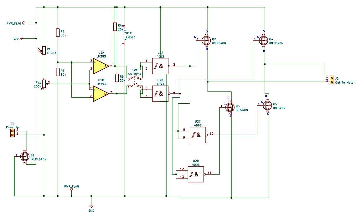
" rel="ugc">
This should work!
Yes it looks this would work, but simulating in mind can have flaws…only a real testing will prove if this will actually work or not.
Hi Sir Swag, do you have a simple circuit that control any liquids from overflow that i can use in a bottle of different sizes, such as soda bottle?
what i means is a circuit that control liquid overflow filling nozle?….
Hi Cindy, a fluid controller can be designed using a transistor and a relay but how will you insert or accommodate the sensing probes on the nozzle?
I will use a nozzle that is small enough that i can insert inside of a soda lid bottle but big enough to accommodate the two wire or sensing probes inside it!…. or do you have any better idea Sir?….. im planning to sell bottled cooking oil in different sizes of bottle/canister, but i want to speed the process by filling 6’s or a dozen at a time!…
If it is oil, then I am not sure if my circuit would work? Because I don’t think oil conducts electricity efficiently. Instead you can use a timer based solenoid tap whose ON time can be calculated to ensure that the timer switches off the solenoid tap after an approximate period which is enough to fill the canister to the required level
thanks for the info Sir, do you have that kind of simple and adjustable timer circuit that drives atleast 6″s solenoid valves simultaneously?…. and if you please, may i have also a circuit for the water filler nozzle?… thanks a lot Sir!
For the timer you can use the last circuit from the following article:
https://www.homemade-circuits.com/how-to-make-simple-timer-circuit-using/
For the water sensor you can try the first circuit from the following article:
Municipal Water Supply Sensor Controller Circuit
Hi Sir, i have other query, do you have any circuit that control a motor thru a relay by way of weight of an object?… i mean the relay will turn-off once the weight of an item reach a particular weight or kilo?….. the process must be manual turn-on and automatic turn-off, and the particular weight/kilo must be adjustable accordingly!… thanks you very much!
Hi Cindy,
You can try the 741 circuit from this article. You can connect a transistor relay driver stage after the LED for integrating a a relay system. The 680 ohms will need to be then replaced with a 10K resistor.
https://www.homemade-circuits.com/force-sensing-resistor-explained/
Hello, I am looking for a circuit diagram for a type of low frequency adjustable flip flop square wave output that crosses over polarity relative to a fixed point. perhaps using 555’s with a +12volt and a -12 volt DC power supply. The purpose is to drive a small low current 12 VDC motor that is a part of a small linear actuator. I wish to control the distance of travel and the time of the actuator without the need for mechanical limit switches or a DPDT polarity switch. The desired repetition rate would be in the seconds. Thank you for your help. Jack
Hi, sorry I can’t figure out how a 555 IC astable can be configured using a dual supply and with an output that would cross over polarity relative to a fixed point??
I want to make Solar Stud Light,
Can you supply Assembled PCB size 40x20x8 mm (Length, width & Thickness including Components) with 6 Nos. LED dia 3 mm
or can you guide to whom we can if you not,
our all moulds are ready only electronics required
Hello sir
I want to design an automatic power reset circuit for my GSM module power supply unit. So that I can reset my main power supply for a couple of minutes when there is no Tx,Rx signal from my GSM module, and when the GSM starts giving data the power supply will return to its initial ON stage, because when I manually reset the power supply the GSM module starts giving data across Tx & Rx. If it is possible by using a 555 timer then please help me with my project.
Hello Arijit,
I am not sure how your power supply can be reset without seeing the power supply diagram. By resetting do you mean switching OFF the power supply.
Yes sir
In my circuit I’ve used MP1584 buck converter for power supply. I need to reset the power supply by applying logic low signal at the enable pin of buck converter by providing 0v or voltage less than it’s threshold voltage limit. So that the power circuit can reset perfectly and give fresh data across GSM Tx&Rx.(if there is data across tx/rx then no reset,if no data across tx/rx for a minute then auto reset.)
OK, so if there’s no data for a minute, then the power supply is reset. Resetting means the power supply is fed with a logic zero only for a second (momentarily), right?? meaning each time the data stops for a minute, the power gets a quick 0V logic ON/OFF signal for resetting.
When the power supply is reset the GSM is switched OFF and ON and the GSM begins supplying fresh data??
I hope I have understood it correctly.
Yes sir, You exactly got my point what i was trying to explain regarding my issue.I need to reset the power supply for a moment so that all the peripheral can restart.
Thank you
Arijit,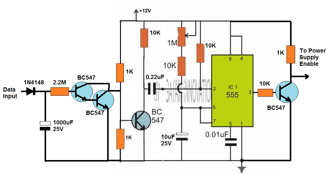
You can try the following circuit:
" rel="ugc">
Thank you, sir. I’ll share my feedback after testing this circuit.
Sure, no problem…
Looking for an AC Induction Motor Speed Controller circuit:
120v
0 RPM to full motor speed.
Not a “dimmer” type circuit, I believe the type that will not harm the motor uses triodes, Pulse Width Modulation … etc.
Thanks in advance
I have a related article on induction motor speed control, you can find the link here:
https://www.homemade-circuits.com/3-phase-induction-motor-speed/
Other than social media, how can I “join” this group?
How can I download some of your teachings, pics and schematics?
You can join us simply by commenting under the articles, we will make sure they are answered. Unfortunately there’s no download option for downloading the articles.
Hello Swagatam. First of all thank you for posting all sorts of very useable circuits especially ckts for LED drivers. I’m a hobbyist too including automotive and I would like to see if you can design a circuit for car test light. But this test light has the capability to display the intensity of the voltage ie, 0-12V using maybe 4 or 8 led’s. Something that will tell me if the voltage its getting is a full 12v or half voltage 6v., or lesser. I’ve looked everywhere and the only closest ckt I found was light chaser like the knight rider. I’m sure you already have an idea of the ckt since you are the master on the field. Thank you again!
Thank you Merdom, you can perhaps try the following circuit:
" rel="ugc">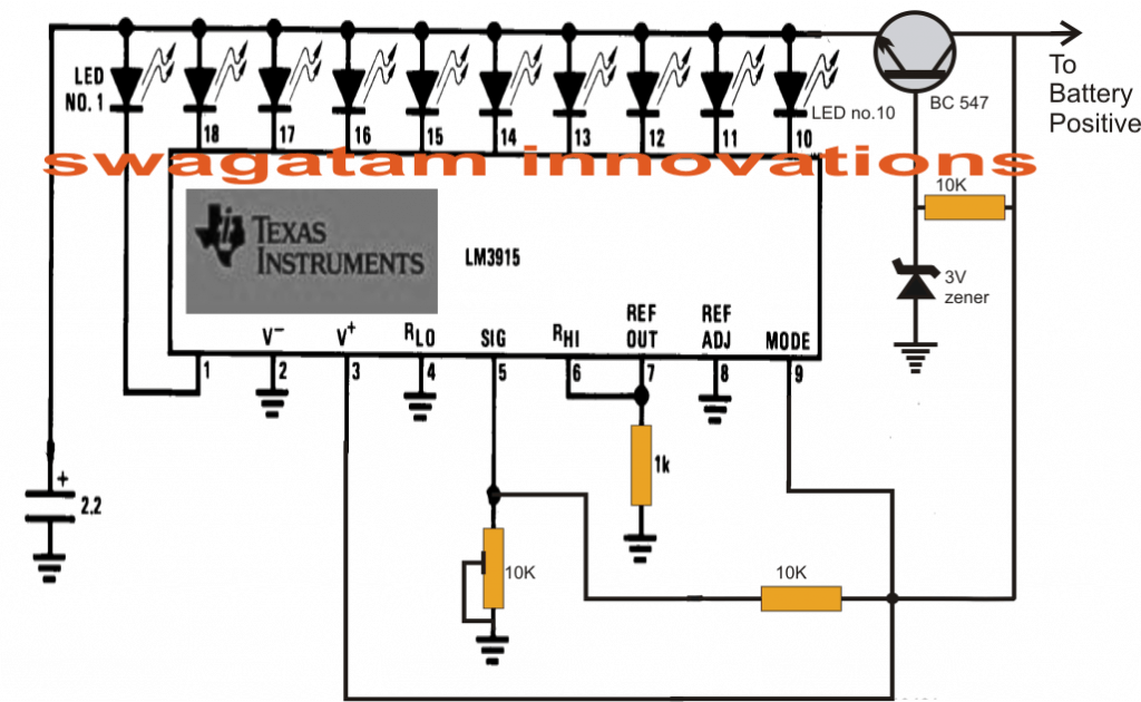
Adjust the 10K preset so that all the 10 LEDs are illuminated when the circuit is connected to a 12V battery or 12V supply DC.
Hi Sir,
I’m a hobbyist, thanks a lot for the circuit and help recently you gave me.
Can I ask you to recommend some good basic electronics books and websites, I want to learn from the basics to engineering level, I know I should go to electronic engineering colleges but my bad nervous system does not allow me, so the books and the web are the only sources for me. But this is just my hobby and not my carrier.
Thank you so much.
I am glad to help you Tym.
Unfortunately I do not have an article which presents a step by step tutorial for the newcomers.
But you can learn from this website by asking questions to me and I will guide you with the procedures.
You can start with transistors first, and a god first project could be a relay driver circuit as explained in the following article:
Transistor Relay Driver Circuit with Formula and Calculations
Next, I will tell you how to replace the relay with other loads like an LED
Thanks a lot Sir, I will learn from your links but I can’t study at a regular time because of my home works and my bad health, so should i contact to your facebook messenger to be convenient?because it is busy to find old comments and they are always growing in this page. And I want to ask another two questions,
1. What will be your advice to learn from below link, is it worth for my times and effort? because some are just theory and/or give no idea for pratical.
https://www.allaboutcircuits.com/textbook/
2. Can you recommend me good basic ebooks or pdf, etc.? because I really want to learn step by step from the basic, please help me.
You are welcome Tym,
Unfortunately answering consistently on facebook will be difficult for me since I am mostly busy answering to blog comments.
The content on the link is good but it might take many years for you to learn them and finally build a circuit, so we should go the opposite way. That is build small circuits directly by learning the bare basics.
If you search online “learn electronics circuits basics” then probably you will come across many good resources which you can refer to, but again these are very elaborate and might require many years of learning to master them. So it is always good to go the practical way, and learn and troubleshoot as you make mistakes, which can be a lot of fun.
OK Sir, so I will learn from this place.
I like your practical way and I also don’t want to be long many years just by reading but I’m reading basic books available in my Mother Language though they are not that good, so I have to Google some good resources for reference and in case of need.
So, I will report after studying the first transistor relay driver circuit.
Thanks a lot.
Sure, no problem.
Feel free to contact if you have any further question or doubts….. I will try to solve it for you.
Hello, Swagatam. I built an inverter using the IC sg3524, it worked pretty well but I’m having issues trying to build a filter for the inverter, because it geneates a loud humming sound when used with some loads like a fan for instance. I tried using a 1.5uf 400v capacitor in parallel with the output of the inverter, it helped a bit but became less effective as I increased the load on the inverter. Please help me out with a more effective filter circuit.
2. Could a filter be added around the Pin 11 and 14 of the sg3524? (That is before the MOSFETs gate).
If possible I’d also love a circuit of such a filter.
If any of the above ideas would work perfectly I’ll use them. Help me out. Thank you.
Hello Chris,
Unfortunately an LC or capacitive filter cannot be added on the MOSFET side of the inverter, it can be added only on the output side of the transformer. You can try increasing the capacitor value to 3uF/400V and check the response. However increasing the capacitor value will also mean some power getting wasted through the capacitor.
Hi Swagatam, I’m developing an electronic mouse trap. I tried to use one of your circuits, from the alcohol dispenser, but I didn’t get success because I don’t have much experience with circuits like that. I only use arduinos and so. I would like to use an 18650 battery, an ldr that triggers a relay for 1 minute and then turns off. The relay must drive a high voltage generator purchased off-the-shelf on ebay, using the same battery. After that, a flashing LED is on to warn that a shot has been fired. As the battery produces from 3.3v to 4.2v I can’t use the 555. I understand that using a simple circuit the battery consumption in stand by would be minimal. I would be very grateful if you could help me.
Hi Marcelo,
When a light beam on an LDR is blocked by the by rat, it triggers ON a relay for 1 minute, this will be the basic working of the circuit. However this cannot be perfectly built using transistors. You will have to use the IC 555 for this. You can use the CMOS version of the IC 555 which is 7555, and these can work with 3V also. The relay will also need to be rated at 3V
Hi Swagatam, I have a request from a customer to build this circuit for him. Please help me with the function of the 1N4148 diode connected in reverse from pin 2& 6 (connected together) on NE 555 ic to VCC.
I assume this is to discharge the capacitor? Not sure though. Your kind assistance will be appreciated.
I have the circuit diagram ,but not sure where to upload it.
Thank you.
Hennie.
You are right Hennie, those diodes help to determine whether the capacitor needs to charge faster or discharge faster depending on the setting of the associated potentiometer. This in turn decides how the output pulse widths are adjusted.
You can find a few of these circuits explained in the following article:
https://www.homemade-circuits.com/ic-555-oscillator-alarm-and-siren-circuits/
My name is Daniel, am a beginner and I have gain a lot from this site. You are doing great thank you.
Dear Sir,
Kindly help us on the design of smps based electrofusion welding machine.
Output: 40-45V DC
Current: 60A max
Sorry, Mehtab, I do not have a 60 amp SMPS circuit with me at this moment.
Following your previous help with my “Touch switch” circuit, I built up the circuit using one of the 4050 ICs on a breadboard using one of the gates as per your diagram and it worked OK. However when the touch pads were merely touched they did not operate, the fingers had to be wet to switch the gate. This is not a problem, I used switches instead and all was well. I did find that when the circuit was switched off then on again the LED lit, this was useful as it saved me having to use separate switches to light up all LEDs, powering up the circuit would light up all LEDs and I could cancel the required LEDs with their individual switches, great, that would do what I wanted.
Before building a permanent circuit I decided to add another LED to one of the other gates using the same capacitor/ resistor / switch configuration as the previous gate. The on / off switches worked well as before, but this time when the circuit is powered up the LEDs do not always light up. Sometimes they do and sometimes they don’t, the results are very hit & miss. A time delay before powering up again seems to help – sometimes. I have also tried switching the +Volt and the -V rails individually and again, hit & miss results. I am concerned that introducing more gates will only add to the problem. Can you suggest a reason / remedy for this ?
">The circuit is actually quite basic so we cannot expect too much from it, there may be some downsides in the design which can be difficult to rectify.
You can perhaps try adding a resistor and capacitor network to the positive supply line of the IC. Meaning, you can add a 220 ohm resistor in series with the positive supply line and add a 470uF capacitor right across +/- terminals of the IC, this will allow a slow start to the DC supply input and hopefully help to eliminate the hit or miss issue.
You can also experiment with C1 and see if that helps to correct the issue
Hello,
I have a question to this post https://www.homemade-circuits.com/tachometer-using-arduino/.
I want to build a tachometer but I don’t have an arduino, instead I have my own type of card with an Atmega16 and I’m programming in Microchip Studio. The main problem is, that I can’t use the function millis(), could you show me how I should programm the timer of the Atmega16 to get the same result?
Thanks for your help.
Fabio
Sorry, my microcontroller knowledge is not good, so it is difficult for me to answer the question.
I am just learning about uni-junction transistors. With all of the information that I have read about them, I have not seen anything about whether there are n-type and p-type devices. For example, would one type be controlled by a negative or positive input voltage if there are the two types of devices. Len.
Unijunction transistors work like oscillators, they do not have N-type or P-type classification.
You can see some example circuits in the following article:
10 Simple Unijunction Transistor (UJT) Circuits Explained
Thank you Prashant, Glad you liked this site!
I will surely help.
But first I want to know the LED specifications. You said it is bi-color, so does the LEDs have 3 pin? Also what is the current specifications of the LEDs, are they 20 mA rated or higher??
Since each LED must get 3.3 V for proper illumination, that means if you connect 218 in series would require 218 x 3.3 = 719 volts which looks impossible to get.
The maximum voltage that can we can derive from a low current AC supply is 310V, so the LEDs will need to be configured in strings, each string having 310 / 3.3 = 93 LEDs. Keeping some margin, we can use strings of 90 LEDs each.
I will design it for you once I get the full specifications of the LEDs.
Hello, based on the name – where are you based TN or Kerala?
Do you build industrial power solutions – looking for a single phase 110V to three phases 208V converter – current can be < 3 amps.
Thanks
Mathew
Hello, I am located in Mumbai. Sorry, due to lack of time it can be difficult for me to accept external assignments.
Hello, I have finally fix my ATX power power supply over current protection problem. Can you help with a circuit. I want to use a voltage regulator 7824 to convert the output 12v to 24v. But the 7824 don’t support more than. Is it possible to put 20 transistor 7824 in serie for a high current support, And include the TIP36 in the circuit with a current limiting circuit for the load. The load current increase when it getting hot I want to limit it to 20a because of the power supply.
Target: supply 24v with a high current and circuit protection (pwm) with a ATX power supply.
Thank you
Hi, 7824 cannot be used to convert 12V to 24V.
Your question is not very clear so I am finding it difficult to understand.
Hello,
I have convert 2 power supply atx ( Liteon Ps-5301-08HF and Dell F255E-00 ) to power 2 loads on 12v each PS. After 30mn the first off and 5mn latter the 2nd off. When I on it now without load it run but it off when I put load. How can I resolve this fault. Is anyway to reset the current protection.
The 12v current rating of the Liteon ps-5301-08HF is 19A max, 300watt and the 12 current rating of the dell ps- F255E-00 is 17A. I have not bypass the current protection and I use each PS separately. The load current is 15a his and increase when he getting hot.
Thank you to help me solve this.
Sorry, it may be difficult to solve your problem, because it is related to the internal circuitry of the ATX which will need to be checked practically.
Sorry, I forgot one thing, battery voltage is 4.2V when fully charged.
You can try the transistorized current limiter version, as given in the previous link.
Hi,
I’m searching for a constant current led driver circuit with good efficiency to drive parallel 10 pieces of 5730 LEDs at 700mA, LED forward voltage drop is around 3.2V, power source is a 1800mAh 18650 battery,
a TP4056 module(with battery protection) is used. I don’t like series resistor because of dimming after some minutes, and I can accept shorter running time. Can you help me please?
Hi,
I have an article which explains a few constant current limiter circuits for LEDs. You can optimize one of them to match your requirements. Here’s the link:
2 Best Current Limiter Circuits Explained
Hello, thanks a lot for the circuits.
I want to use transistor version but I don’t know which transistor part numbers to use for my low voltage input and for possible lowest power dissipation, and if possible I prefer mosfets for their efficiency.
Input voltage ≤ 4.2V (18650 battery)
Led Vf = 3.2V
Total Led current = 700mA
Can you help me please?
MOSFET will not work with 4.2V, so you will have to use a BJT based current limiter circuit.
For T1 you can use TIP31, and for T2 you can use 2N2222
I AM INTERESTED IN THE RF signal jammer circuit AND OTHER TYPES OF CIRCUITS FOR MAKING JAMMING DEVICES. DO YOU HAVE A COURSE OR BOOK THAT I CAN LEARN THIS? THANK YOU CARLOS
I appreciate your interest and hope you succeed with the project, however I do not have a detailed course book for this at this moment.
Greetings!!
I need to reduce a variable input voltage from 9V to 60V to 3.3V.
The circuit will receive a pulse from 9V to 60V, this pulse will trigger a digital pin of the ESP32 which will make it perform a function.
Sir can you help me.
Thank you very much in advance!!
Hi Carlos, are you looking for a 60 V to 3.3 V buck converter circuit?
Hi, I am looking for someone to design simple high efficient voltage regulator with ATX terminals.
input 12V PCIe 8 pin cable used for powering power hungry GPUs and convert it to Molex 4 pin connector with 12 & 5V…which can be used with any commercially available Molex extension or Molex/SATA adapter cables.
It is for a 100+ HDDs hobby server project. I do not want it for free, but I need electronic engineer hacker ready for challenge. So far, I have contacted at least 5 people…everybody says “no problem, send the details”, and never reply 😀
If you are interested, please contact me via email. I will send you all details/requirements.
thanks DavidH
Hi, I am not sure about the pinouts of the cables that you are suggesting, however 12V and 5V regulators could be built using buck converters. Buck converter would be required because making 12V, and 5V regulators using linear ICs like 7812 and 7805 can cause a lot of heat dissipation and that wouldn’t be efficient.
Hi Swagatam, thanks for reply. I have full details in PDF, but I cannot find an engineering able to design it :o)
Is it possible to hire you, please?
I am sorry David, that might not be possible due to lack of time. I can only help with general circuit ideas. Solving elaborate circuit queries can be difficult for me.
Hi Swagalam,
Sorry, it’s Malc again. Re: my question on switching 9 outputs, I also intended to ask whether this would be easier / possible using an Arduino ? I have an Arduino Uno and a fair bit of compatible kit but not great when it comes to the code.
Hi Malc,
For 9 LEDs, you will have to use 9 such gates using two ICs. Yes using Arduino may be possible but my Arduino knowledge is not good, so it will be difficult for me to solve it for you.
Hi Swagatam, thanks again for your super fast reply. I will look into the possibilities of both ideas. I have access to the usual Arduino forums etc. so it should keep me out of mischief for a while. Thanks again for you input.
It’s my pleasure Malc, all the best to you!
I am trying to construct a touch switch circuit to switch 9 LEDs on and off independently. I have managed to switch a single LED on and off using a 555 IC connected as a touch on/off switch and this worked well. Obviously I could use 9 of the 555 ICs to achieve this but it seems a clumsy way of doing it. Is there an IC capable of switching 9 outputs independently, or perhaps doing the job with 2 ICs ? I would be grateful for you help / advice.
That may be possible if two switches are allowed for each LED. One touch switch for ON and the other for OFF operation.
Here’s one simple design that you can try. A single gate from the IC 4050 has been used here. Each 4050 contains 6 such gates, therefore 6 LEDs could be operated independently using a single 4050 IC:
" rel="ugc">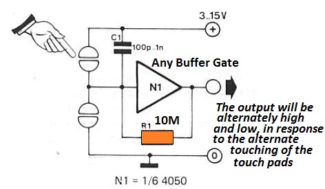
Many thanks for your prompt reply. Your suggestion looks good. I will certainly give it a try. Thanks again.
Malc
Sure, No problem!
I would like you to help me to design a circuit for controlling the speed of electric motor to use it driving car instead of fuel engine.
What is the specifications of the motor?
Thank you very very much
Hi. I am rebuilding a caravan in the UK and want to have a portable solar panel to support the various 12v equipment I’m having. My problem is finding the right sized solar panel. I will be having a few 12v LED lights, a 1000W inverter, a small 12v/240v tv, a 12v fridge and some USB sockets for phone/lap top charging. I tried working out what the load would be on the LED’s but I don’t have a degree in electronics to understand what is being said online. Any help would be greatly appreciated. Thank you in advance for this great service you are offering to know-nothings like me!
Hi,thanks for your question! I understand your requirement, however for calculating the solar panel specifications we would first require the current and voltage specifications of the various loads. So, for example for the 12V LED we would need to know the current spec of the lEDs, then for the 1000 watt inverter we would need to know the DC voltage which the inverter would be using. Similarly, we would require the current specifications of the TV and the fridge.
Once we have the voltage and the current specifications of the loads we can then multiply the two values to get the wattages of the respective loads, and then add them together to evaluate the approximate specifications of the solar panel.
Wow, thank you for such a speedy response! I think I might be able to finish the calculation off once I understand how to determine what the Wattage of the LED’s will be, which is the confusing bit. I will be having one set of 4 x 12v LED’s with a power rating of 0.4W and a current draw of 0.03Amp per light. I will also be having one pair of the same, together with 3 individually controlled light fittings. As you so very kindly asked, I will also be having a 12v/240v CRX80 Dometic Fridge rated at 48W with a rated current of 5.6A and 0.56A at 240v. The DC voltage for the inverter will be 12v. The 12v TV/DVD player will be approximately 36W with a power supply of DC 12v 3A. Also I was thinking I would need 2 leisure batteries…. Hope this is all you need. Regards..
12V LED wattage will be
0.4 x 4 = 1.6 watts
0.4 x 2 = 0.8 watts
Fridge is 12V 48 watts
Inverter is 12V 1000 watts
TV is 12V 36 watt
Total wattage becomes = 1086 watts or simply 1100 watts
For all these loads working together, you will require a solar panel with an approximate specification of 15V, 1200 watts
Oh! That would be impossible for me as I wanted to hook up a portable solar panel and thought a 100Watt one would do. Inverters are used to convert DC to AC current, correct? If so, to run something like a microwave, I would need a 1200W solar panel, which is impractical with a caravan, so how do people do that? Sorry to go on, but the more I find out, the less I know…
For operating a 1200 watt load you will have to have a 1200 watt power source, right? There’s no other alternative for this. The power has to come from somewhere, in your case it is a solar panel…so the panel has to be rated at 1200 watts. It is indeed impractical to run a 1200 watt load in a caravan.
Thank you for your help. This is such a difficult area for me to understand, having no knowledge in electrics, but you saved my bacon! You are a real gem!
It’s my pleasure Arthur. Glad to help!
I have a “Kidde” detector in my living room and it takes batteries. There is a “First Alert” smoke detector in the bedroom. It does not take batteries. Instead it is connected to wiring in the wall. It gets its electrical power from the house current. After it detects a fire it sends a signal through the wire to a phone box in the basement and the fire department is contacted. Are either of these alarms an ultrasonic alarm? Thank You.
It can be difficult to tell without practically seeing the device. It can be based on an ultrasonic sensor or maybe a standard smoke/gas sensor
Good evening sir,
Sir you have deleted a post based on hho gas generator, what happened sir?, and can I have the schematic or the pdf for the project?
Hi Tun, actually it is dangerous to generate HHO gas at home, that is why I deleted that post. You can check the following post and use the set up to generate the HHO gas using 220V DC. But remember this set up is also dangerous and you would be doing it at your own risk:
How to Generate Pure Oxygen and Hydrogen at Home
Thank you, Sir. Your reply was corroborating what I was thinking in my head. I cut my teeth in the days of vacuum tubes, but obviously made the transition to solid state devices many decades ago.
I was recently monkeying around with a circuit for a Unipolar Stepper Motor controller, and came upon the fact that since the ends of the four coils were tied to IGFETs, the two ‘high’ side leads had to go to a ‘switch’ to shut off the current when the motor was not being energized. The obvious solution was to use a high-gain PNP power transistor (TIP12x) as the source, but then I was thinking about making sure that this transistor was guaranteed to be cut-off when the motor wasn’t being powered. In this case, it seemed logical to ensure that the transistor was biased off, especially since the motor is part of a machine, and the mechanics & control of the machine cause the overall electrical environment to be somewhat noisy. I just want assurance that I was thinking along the correct pathway by using a cut-off resistor. As I previously stated, I saw many instances where a PNP transistor was used in a current source, and there was no bias resistor included. This disturbed my logical thinking.
So, again ….. THANK YOU for your reply. There is no need now for you to reply to me. I appreciate your feedback.
karl t.
Thank you Karl, for your detailed explanation, I appreciate it a lot. All the best to you.
Are you available for freelance consulting?
I am available through comments on this blog. You can ask your questions, if possible I will try to solve it for you.
Hi Swagatham
In one of your blogs showing the circuit for proximity sensors using IC 741 what is the value of the pot used and which is the transmitter IR LED and which is the Receiver led it’s only mentioned as IR led and Photodiode led, I’m all confused which is which
I have two IR LEDS one is dark colour (Receiver)and one is clear (emitter)
Appreciate a reply along with the link for this blog
I tried out this circuit with a 10k pot but it does not activate the relay with motion in front of the IR LEDS
Hi Val,
I have updated the diagram with the relay and all the other details in the following post:
https://www.homemade-circuits.com/simple-proximity-sensor-circuit/
Hi, I was looking over your SG3525 circuits. Nice work. I was thinking about building a Peaking Power system to augment a portable generator set output with a solar-battery system, during short high-power demand periods. To connect the inverter to an already operating generator set there are three issues to consider, Voltage, Frequency and Phase. Setting voltage first and then frequency second is not too challenging using the SG3525 invertor with some smart adaptations (Arduino). Comparing the phase for synchronization and relay lock the systems together is a bit more interesting. Have you done anything like this, or have any ideas where to point me for study.
Hi, thank you for liking my work, appreciate it.
However the question you have asked looks too complex for me, I haven’t yet done any work on this concept.
Thanks for your reply. If I have any luck I will share it with you.
Sure, no problem!
Thank you, sir, for your corroborating reply. The reason I asked this question is because in many general load-switching circuits that I’ve seen, some show a ‘cut-off’ bias resistor going from a positive supply rail to the base of a PNP transistor, acting as a switch. Other times not. So, I was wondering whether this was laziness, frugality, forgetfulness, or just plainly unnecessary. In biased circuits where there is an AC component for amplification or switching, it’s understandable to set up the transistor as an emitter-follower to allow for the full excursion of the signal, but with the simple off-on scenario, I wasn’t sure.
Finally, would you suggest a typical % range of values, or just a ‘hard’ range ….. let’s say for a typical 2N3906 class, and maybe either a 5v or 12v pos. rail, would you recommend 100K ohms, more or less?
Thanks again.
karl
Thank you karl!
Even if you don’t connect the base emitter resistor still the transistor will remain cut off during the absence of a base signal. However, without the base emitter resistor the transistor base could be floating and attract stray signals from the atmosphere and might go into conduction mode…that is why it sometimes becomes crucial to add the base emitter resistor just to make sure the transistor remains perfectly cut off while there’s no input signal at its base. Typically any value above 100K will work fine, although it depends on the existing base transistor with which this base/emitter resistor forms a resistive divider.
Hi Swagatham
I’ve sent you three diagrams based on your circuits and discussions to you email as I don’t have multimedia and I request you to see if they are ok and will work out
Also need the values of the components used in the first transmitter circuit and which of the two is better
Thanks & all the best
Hi Val,
I have answered to all your previous questions, you can check them out
Simple question, maybe?
When using a PNP transistor in a source mode, does it make sense to put a large value resistor from Vcc to the base as a ‘cut-off’ source,
or is this just a waste of money by adding an unnecessary component to a typical circuit?
Adding a capacitor from positive supply to the base of a PNP transistor will not cut off the transistor, it will create a momentary switch ON/OFF delay for the transistor
Mr. Swagatam,
My question was not about putting a capacitor between the Emitter & base of a PNP transistor; it was about putting a high value resistor between the base & emitter of a PNP transistor when the transistor is being used as a high side switch. The emitter is connected to the voltage rail, the collector connected to a load (relay coil, LED, etc.), and the base is connected to an active low signal through a base current-limiting resistor.
thank you.
I am sorry, I misread your comment. Actually, yes it is a good idea to keep a high value resistor between base/emitter of a transistor regardless of whether it is a PNP or an NPN. It ensures that the base of the transistor is never floating in the absence of a base signal.
How do I insert the circuit in this post
Hi Swagatham
I have this sensorTSOP 1738 and tried it out with a remote control the led is normally ON and when I press any button on the remote control the led goes off.
What transmitter circuit should I use so that when interrupted it turns the led off and instead of the led can it activate a relay circuit that you can suggest
Sorry Val for all the trouble, you cannot inert the images in this website….I was actually suggested you to post your comments with images on my social media accounts such as facebook, facebook-page, Instagram etc, whose links are given above.
I hope you will not mind this.
Thanks Swagatham for your reply
I don’t have any of the media like Facebook etc
I’ve seen a post of a similar circuit I shall try it but I want to know what transmitter circuit should I use to keep it in a mode that when the signal is interrupted it should trigger the relay on
The transmitter and receiver should be about 6 to 8 feet apart
Please I want to know how to write a code using assembly language programming that will get an input from ultrasonic sensor and send it’s output to a gsm module and 16X2 LCD.
I wish I could help you, however my programming knowledge itself is not good, therefore it would be difficult for me to help you in this regard
Okay Sir…. Thank you.
Can you please provide the exact link of the article that you are referring to?
Hi! Mr. Swagatam
OK, I see your concern that you are busy.
I am very thankful that you allow me to use your design. And I also very pleased for your deep kindness that you are also interested to help me in technical matters.I end u some question on quora hope u could help me
Thank you Ahmed, I am always glad to help. Can you please repeat the question which you asked on Quora, if it’s possible I will try to help.
Can I use that one ☝️ DC Adapter (12 v 2A )to charge 2 of those batteries (6 v 7.0AH/20HR) connected together? If yes how long time would it take to full charged?
If you connect the two 6V batteries in series then it will require 14V input DC for charging them, the 12V adapter cannot be used for charging the two 6V batteries in series.
Thank U For Your Kindness So What If I Separate Them And Try To Charge Them One By One Would It Work To Conect The 12 V Dc Adapter To a One 6 V Baterry . I Have Another Question I Had Some Contents Parts Which I Dont Know What Is It And What Is It Used Fore But I Dont Know How To Show U Its Pictures , Can U Tell Me How To Show U It
I sent u it’s pix on messages on Twitter
Hope u tell me more about them
Yes, you can use the 12V to charge the 6V batteries separately through a LM317 voltage regulator power supply. Just make sure to adjust the output voltage of the 317 to exactly 7V, and then apply this 7V to your 6V battery.
I checked the images that you sent me on twitter account….however unfortunately I could not figure them out, they look like they are some kind of varistors or MOVs.
Thank you for your advice. I have already provided sufficient warnings in the article regarding the dangers of using capacitive non isolated power supply, and I have also suggested that the circuit must be properly insulated while using.
By the way none of the string light circuits I have seen in the market today use isolated DC, they all use AC mains and are thoroughly insulated to ensure the necessary safety to the users.
Hi, your article on Smartcars and Arduiono is very valuable. I am a former Electronics Engineer working on a proof of concept for smartphone operated door and ignition locks. I have sent you a FB connect request. Pls add me on FB.
Thanks.
Hi, Thanks, Glad to know about you…I have accepted your friends request.
Hi! Mr. Swagatam
OK, I see your concern that you are busy.
I am very thankful that you allow me to use your design. And I also very pleased for your deep kindness that you are also interested to help me in technical matters.
I am preparing things and thank you again for your great wish that I will be success.
with Best Regards!!
Dawit
You are most welcome Dawit…
Dear Swag, I’m Claudio… ;-)… excuse me… could you imagine other features of inductor?… furthermore… someone thinks that the duty cycle should be in microsec order… what do you think about a ne555 flip-flop with 2n3055 to bear the high extracurrent? Bye
Hi Claudio 😉 Could you please tell me which schematic or concept are you referring to? I’ll try to answer to your query…
Hi Swag..;-)… I’m sorry… I’m referring to a simple schematic about the «cold electricity»… in the free energy section…
OK got it, yes you can try a IC 555 based oscillator for creating the collapsing the magnetic field, and subsequently cold electricity, however I am not sure what frequency would be ideal for this operation…
…ok.. but for the inductor?… its features is very vague… ;-(… can u help us? Thanx
I can help only once I test these concepts practically, I may do it sometime soon and will update the results here for sure…
Hi! Mr. Swagatam
I am Dawit and Electrical Engineer
I have been working in different industries by giving maintenance for different electrical control system. Now when I come with your site and see your creative works I realy appreciated you and I have been myself ignited to such works and turn them to a business in home based. of course, I have not yet facilities for such production. What do you suggest me to have, and toward degree would you cooperate me to such manufacturing and turn them to business if it is your interest to work with your design works. In our country, Ethiopia, a lot of your works have business. for example home air ionizer would have a lot business In our gas polluted town Addis Ababa.
Thank you in advance for your attention
Dawit
dave4me60@gmail.com
I
Hi Dawit,
I appreciate your offer and enthusiasm, you can feel free to use my designs for manufacturing and doing business in your country, however I personally wouldn’t be able to cooperate in this venture with you, because I am already too busy with many assignments here, so getting involved with any external business would be difficult.
Anyway I Wish you all the success! Let me know if you need any help regarding any technical matters, I’ll be happy to help!
Dear Swag,
Please help design for me an instructable UNIVERSAL SMPS for High Power Amplifier voltage ranging from +/- 50v to +/-100v Dc.
Thanks.
Dear Erntec, I am sorry I am not good with designing SMPS circuits, therefore presently it won’t be possible for me to help you in this regard..
Thank you very much for replying sir.
Is ok if you can give me the digital clock without the date, But will the time be set to work both French and English time?
As for the link you sent, thanks very much but now my question is, if i assemble the circuit, can it be connected to the CDI as it is then the car speed be set to certain frequency? if yes then good, it will even be good because i can use one of the leds to energize a transistor as a switch then start to think of what to do next…
i look forward to read from you and thanks a lot.
Nkwenti.
Hi Nkwenti, I have a few digital clock circuits but I am not not sure whether translation may be possible or not? You can see them below
https://www.homemade-circuits.com/arduino-digital-clock-using-rtc-module/
https://www.homemade-circuits.com/7-segment-digital-clock-circuit-using/
https://www.homemade-circuits.com/digital-clock-circuit-using-arduino-and/
https://www.homemade-circuits.com/simple-digital-clock-circuit-explained/
Yes definitely, you can use the earlier referred link to detect CDI spark rate and accordingly set the corresponding output from IC LM3915 to trigger a transistor stage for controlling the CDI
Dear sir.
Hope all is well with you, i must take my time to first of all appreciate all your good efforts and help you offer from your website,
i have enjoyed a lot from your website, but i came accross a project from your website and i wonder if you can help do some modifications so that i can use it as my test projects coming up, i am basic but to build any circuit i have no problems doing that.
i came accross a circuite under auto-mobile projects, the car speed indicator, dear sir, is there any way you can modify the circuit in such a way that, when the CDI gives signal about you over speeding, a circuit automatically stops your engine for at least 5minutes?
Then as for the other help i will ask you is that, i am in need of a digital clock schematic that has date/month and time, if the digital clock can indicate time in French and English it would be excelent.
thanks for your understandings and i will be looking forward to be reading from you.
Nkwenti.
Thank you Nkwenti,
I am sorry I do not have the digital clock circuit with month date, but you can perhaps find through a Google search.
For the car speedometer cDI controller you could try the following concept:
https://www.homemade-circuits.com/10-led-tachometer-circuit/
From the 10th LED or 9th LED of LM3915, an IC 555 monostable could be added whose output could be integrated with the CDI for stopping it as soon as the sequence reached these LEDs.
You can first verify the above circuit then I will proceed and tell you how to configure the IC 555 monostable.
Thank you very much. I’ll try it out a.s.a.p.
What is the difference in power consumption between the first and second iteration of this design?
I’m probably being a pain, but can you give a breadboard illustration of both circuits. Or maybe a link to a VBB design.
You are welcome Andreas.
I won’t recommend a breadboard assembly. This must be firmly assembled and tested on a veroboard, by soldering.
Secondly the resistors involved with the LDR transistor will require some tweaked until the desired results are achieved.
This circuit will not consume anything while it is in the standby mode…
Thank you, I have made the circuit with both designs….555 and bjt, had to play around a lot to get both working because of the difference in ldr’s. I added a cell phone to the setup with a relay connected to the dial button. Now I want to add a power failure backup utilising the cell phone’s own battery and over charge protection and also add a comparator circuit to both ldr’s, so a would be thief cannot just shine his own laser to disable the system.
I would very much appreciate if you could maybe start a new post incorporating all these ideas into one circuit. I see you have a few other circuits that use some of these individually, but not one “fully incorporated” system.
Again, thank you very much for you patience and all your help.
I am glad you could make it successfully. In order to make the design foolproof you could probably try making the opamp based circuit explained in the following concept:
https://www.homemade-circuits.com/how-to-build-dual-solar-tracker-system/
the shown motor could be relaced with an alarm, now if the intruder tried to balance the LdRs artificially he would fail drastically causing the hooter blow of.
Thank you, you have been soooooooo much help.
I looked at the circuit you suggested sorry….I struggle a bit still with learning electronics…..how do I tie this into the 555 circuit, does pin 1 and 7 of the op amps go to pin 2 of the 555 as trigger?
You are welcome Andreas, sorry I did not get, which IC 555 stage are you referring to? the suggested LM324 will not require any other circuit, it has two LDRs which can be used with the laser for getting a foolproof implementation.
Hi Swagatam,
I made your smart alarm system that a guy from South Africa proposed recently and I really love the idea. Btw, i’m also from South Africa slightsmile emoticon ( the laser alarm system with two ldr’s,
“Smart Laser Alarm Protection Circuit using IC 555”)
I was wondering if you would be able to expand on the idea as follows :
I would like for the system to have a back up battery, so that it is tamper proof and also wanted to know if the same result could somehow be achieved without using the 555 as it is very power hungry.
Also, if you could incorporate a potentiometer or something so that the light intensity can be adjusted on the ldr’s. I am planning on putting mirrors around an area of 4 meters by 2 meters square for the system and the laser light is quite diminished by the time it has gone around that whole area.
If possible, could you also let me know what a “kit” like this would cost.
(Sent you message on Facebook, not sure if you got it, so sorry if i’m repeating the same 😉 )
Hi Andreas, I am glad you could make the project successfully.
I have noted the improvements suggested by you, and will try to update the article with the modified design soon.
Thank you 🙂
Another question, if i may…..
Could one include various RC combinations and toggle them with a sweeper switch? I.e. 10 second RC combination, 30 second and 1 minute on a 3 pin sweeper switch so that you can choose the duration that the alarm will sound?
Also, which changes would one have to make to include a gsm combination as in one of your other posts or can one just tie the one you made in on the pin three of this circuit?
Again……Thank you very much for your help and dedication with this site. YOU ROCK!!!!!!
yes that’s also possible, in fact you can use only the Capacitor for the selection and get different time periods.
sorry I am not too sure about the GSM integration, it will require some thinking…
Thank you. 🙂
Andreas, I have updated the design under the following article:
https://www.homemade-circuits.com/smart-laser-alarm-protection-circuit/
Thank you for this site, it is a great help to a great many people.
Thank you very much Andreas!!
Hello Sir,
Hope you will be good.
I am a big follower of you, will you guide me how i design 2.5kva gasoline generator AVR or please share if you have any circuit related portable generator AVR.
Waiting for your guidance.
Regards,
Waseem
Thank you Waseem,
Although I am not sure how to control a generator output, it may be perhaps done by controlling the CDI ignition rate through a feedback from the generator output voltage…if possible I may present the concept as a new article.
sir how to dim and use 6 or 12 volt batery to drive 50 watt led ( using TL494) thankyou for your attention sorry my bad english.
You can try the following concept
https://www.homemade-circuits.com/5v-pwm-solar-battery-charger-circuit/
you can remove the coil and associated diode.
Hello swag. I am a regular visitor of you blog and it is awesome.
I am trying to make a modified sine wave inverter. I have one unused raspberry pi 3, so I though of using it for generating pwm signal and use it with a square wave inverter. Will it work?
Thanks Manash, you can use any PWM source to create a modified sine wave, it doesn’t matter whether it is from an ordinary circuit or from a Rashberry pi or Arduino, all will produce similar results
But the pwm output voltage is 5v. Can I directly connect it?
No that will not do, for that you may have to employ the second circuit configuration from the following article
https://www.homemade-circuits.com/arduino-pure-sine-wave-inverter-circuit/
Hello!
First of all I’ll appericiate you for your work.you are doing very good job…keep i up!
Second I need a circuit which will need the following paramters.
1. Run the motor after specific interval e.g after each hour.
2. Motor should run off when there motor is not supplying water in upper tank (means dry run protection in upper tank.)
3. If upper tank is full,motor should not run.
4. If there is high or low voltages from a certain voltages than motor should not run.
5. If there is power failure during startup, than motor should start after delaying some certain time when power restores(delay startup).
I hope you can help me on this.
Thanks in advance.
All these circuits are already published in my website in separate articles, you can search these articles and join them together for fulfilling the specified needs…
Thanks for your reply!
I am very initial level hobbiest and could not enough knowledge to merge different circuits according to my requirement. Kindly guide me some so I can up track on my requirements. Or atleast give me list of you articles with guaidence to join these circuits which you think that can fulfills my requirement.
You are doing very good work, and your website lead me to stay on from yesterday and i have bookmarked your website.
Thanks Umar, appreciate your interest.
I think you should proceed step by step.
for the timer circuit you can try the following design, if you succeed then we can move ahead with the next stages.
https://www.homemade-circuits.com/submersible-timer-circuit-with-pause/
Sir I need ur help
I want to make a 2.5 kW inverter
So sir give ur personal mob no
to u and yr family.
Sr i want to glow up 7000 to 8000 leds with 220 v ac and want them just blinking.
Kindly guide and help me giving a appropriate ckt.
Thanks and best regards in advance
Hello Sir,
My name is Jameel Ahmed
my english is not good.
I want a Electricity Power Saver circuit for Home Application for saving power consumption,
hello sir
sir, In my flat there is a problem of light cutoff when alternating current gone. Our building's gate keeper start generator and we have to switch off all extra load (e.g fridge, a.c etc). There is nothing to notify when light comes again. Is their possible to detect generator current/voltage/freq. or alternating current/voltage/freq. . Please help me sir
my gmail id is shivamchauhan20sep@gmail.com
Hello sir
I am chetan from karnataka
Sir is there any circutes regarding monkey repeller
kindly help me about this.
Hello sir,
I want to make 3RCA TO 6RCA Female cable and 3RCA TO 3RCA+RJ45 Female cable. Will you please provide me circuit for it. Pls do the needful
Thanks
Amandeep
Hello Swagatam,
I would like to meet you and discuss projects for welding machine. I am Mumbai based. My phone – 9820212263.
Any time will be convenient to me. Please reply.
Much awaiting,
Nishant
hi sir
thanks for this valuable blog
please post a Brushed DC motor speed control circuit up to 10hp
HI Sir
Thanks for this valuable blog.
can you post a brushed DC motor speed controller circuit up to 10 HP
Hi sir i need a ckt for a present. Would you plz make a ckt for me
Hello Sir
Do you have schematic of electric bike especially brushless motor and controller , how can i make a ebike for my self
thanks
I want to make a led lighting circuit which will show the blood flow of human heart including open close indication of valve. Can you help me to do this project providing circuit diagram and details . I want to use 230 v ac supply for input. Kindly reply me in my email id uniqash@gmail.com.
HI SIR,
I NEED 3PHASE VFD CKT
i like to build led sign but i have small knowlege with the pic16F And attiny 2313 That i try to study them. I asked my friend to help me because he has many knowlege in electronique than me.
My dream is to drive many leds on one pin µcontroller. But i can't make it now.
Perhaps swagatam will help me to solve this problem,thanks a lot for your good site.
Hi Swagatam,
This is RSBirman.
Do you have any circuit which indicates open earth and has a NO/NC relay contacts which can trip the contactor if the earth is not connected and this will avoid the instrument from getting on.
The sensitivity should be adjustable.
Hi,
I recently by mistake bought LED bulb(Great Value) from South America which is 110V. But I want 220V LED Bulb as I'm in Sri Lanka. Now I'm trying to do some modification on LED driver. Please help me to do this & Fix this bulb to use from 220V. Which parts need to change on the driver ?
220v Ac COB 5w(5A) Led is getting excessive heat after connection. Also not lasting. How can I solve this problem???
Hi Swagatam,
I need a countdown timer with a relay which can be set to 1 to 5 minutes.
I would like the timer to show the preset time on 7 segments e.g. 3 min. = 180 or 3.00
When the time counts the 7 segments shall show the remaining time.
When the time is up the relay must switch off.
I don’t have Arduino and no skills in PIC programming yet.
Can you help me out with a circuit / schematic?
Thank you in advance,
Henrik
Dear Mr. Swagatam Majumdar,
My name is Srinivas Chakravarthi & I am working on Electro-Chemical project, for my lab work, I need an Universal Power Supply (AC/DC) with variable Voltage, variable Current & Time controlled Polarity Switching.
My requirements are:
Variable Voltage 0-100 (V),
Variable Current 0-100 (A),
AC or
DC with or without polarity Switching (1 to 10 minutes variable).
If you can make one such universal power supply unit, I shall be very much grateful to you.
Thanks & Regards,
P.Srinivas Chakravarthi.
09440840989.
Vijayawada,
Andhrapradesh.
Dear Mr.Majumdar, I am Kamal Kumar from Chennai.
I hope to find a good circuit for a battery eliminator with output dc power ranging from 1.5 to 12 or 15V and with its PCB design etc. can you kindly give me the same I will be very thankfull. I have searched every where on the internet but nothing seems good for what I am looking for. Thanks in anticipation.
Hi Swagatam I am a fan of ur work..
I need a help.
My laptop and mobile over charges each night.
I want to creat a circuit that can start supply at desired time later i.e that 2 or 3 or 4 hrs later and supply should should be ON again for desired time .
I would have to enter how much time later Supply will be on and off..
Thnx man, Your work is really great.
Please inform me if you are working on this project.
Hello Swagatam. I was thinking about put a sensor on the gasoline line from my motorcycle tank, near top, between the tank and the carburetor, that would consist of a pair of (innox?) leads like some mm separated from each other. This would detect the electrical conductivity inside the line, in direct contact with the fuel and while there is gasoline wetting it, it would output 0 volts, and when not (i.e. gasoline is ended and the line is becoming empty from the top), it would output positive (12v?) so I could light a warning light on the dashboard to avoid getting engine cut on a sudden. I can quickly turn the valve from to reserve position in this case. So when sensor wet, 0V(0); sensor "dry" 12V (1). What do you think? Thanks Sir.
Hello,
I love your website! I was looking at your circuit "twin or split battery charger" and I don’t see a value for the resistor between pins 1 &3, 7&5 for the LM358 is it 1k? I’m going to make a printed circuit board of this design using photo etching.
My goal is to build a circuit that will charge one battery while running off another battery and when the run battery falls to a certain voltage level, switch to a charged battery. I am not looking to make an over-unity device; I am interested in experimenting with energy recovery to create long pulse motor run times. I expect the system to eventually die out but I want to see how long that process will take using air coils and back emf harvesting.
Would this circuit work if I replace the batteries with two 100F 2.7v supercaps? Since the caps charge faster than lead acid batteries, this may help the efficiency of energy recovery during the run time windows.
I love building things and your awesome ability to design such cool circuits makes people like myself enjoy hours of building these cool circuits and watching them come to life.
Dear sir, i am very fond of u, by u i love electronics, u r really genius, u made electronics very simple.
Sir i would like to request clap switch and timer circuit for 8 volts led bulb which remain on for a long time
Please help me to solve the circuit.
Thanking u
Yours
hello sir,
i really liked the way you reply to queries and your good heart of sharing. May God bless you.
please sir, am working on a project titled "remote controlled DUAL BAND MOBILE PHONE JAMMER"
i hae tried searching for a working circuit diagram but hae been able to find one. please i will appreciate it if you could be of help. thank
johnson
Hey mate,
Would you be knowing the circuit for a zero cross detect for a transformer ?
Hi Mate,
I am designing a Spot welder Controller with an Arduino and there is a need for a in rush current limiter. Would it possible for you to design the "In-rush-Current-limiter" i have read that it can be done in several ways. I will be using this to drive a Microwave oven transformer modified by rewiring the secondary to 3 turns of 3AWG wire for spot welding 18650 cells.
Hi Swatagam!
I would like to know if you could make a circuit that can activate a 12V 600ma stepper motor for 10 or 20 seconds every 3 hours or so. is that posible?
Kind Regards,
David Montenegro
Sir, plz help me in making a circuit with following details. A 12 V relay is to be connected such that a momentary push switch turns it on BUT but after release of switch the the relay should not turn off immediately, rather it should turn off after some time say roughly 1minute. Thanks
Hi I need a Nokia Mobile battery( 3.7v) driven simple Bluetooth stereo amplifier circuit diagram.Please develop it.
Hi,
I would like to convert ATX power supply to a variable power supply, can we do it ?
Sir your projects are really great but I am a student of class 10 sir can you help me with a idea of creating a project for science expo.
Thanks Anand, provide complete details of your requirement, I'll try to help.
i need to assemble variable frequency(a pot can be use on output of 555 for variable amplitude) square wave funtion generator with frequenciies 1 Hz to 1MHz ,flexibility to vary amplitude of output ,555 should be used in astable mode and axact 50% duty cycle can be obtained on output plz help me sir in desining the above circiut i will be highly thankful to you
please sir i want talk to you over phone is it possible? my mail address is
ravishimla1965@gmail.com
Dear swagtom sir! I have heard that we can communicate by intercom using main ac power line home to home , i need communicate with my friend , there is about 3km-4km between our houses, but our ac power line is same, can you give me circuit communicate with him? please!
Amit, I'll try to do it soon.
dear sir, i will enough grateful to if you can provide me the complete circuit for e rikshaw with solar system alongwith complete electronic component value, please send it to amit46vm@yahoo.com/gmail.com
regards
amit
This is just a simple question :
Can i use a lower Ah battery charger(say 20,30)to charge a higher Ah battery ie 110Ah?What are the consequences?
What is the difference in the charger circuit in both case?
Hello Sir
This Is Aravind Sir
I Like To Know How To Make A Transformer And Its Calculation And I Google It But I Cant Find The Proper Calculation Method And I Find Around 7 Method Of Calculation But Its Not Proper With Manufactures Standard And Can You Please Help Me To Know It Sir
Thanks You
Iwant to make my own polybag sealer can you give circut of this
Hai Sir, this is Swetha…, Am persuing Btech final year. Want to do live project. I want Gravity Light project. Can you please send circuit diagram and report please. swetha.bindhu403@gmail.com
hi sir i can you please design a circuit which will output 9v dc from a 12v battery efficiently . it can be by using ic 555. this will be use to run a rc toy car using 0.8A max. if possible can it be a variable output voltage dc. i have a 2n3055 transitor ,MJ11015 TRANSISTOR.
hello sir ,this is vinod from mussoorie near dehradun.i am not an engineering student,but i have lot of interest to make different electronic items . sir i would like to know that is it possible to use usb drive in normal tv without hdmi and usb port, by putting some type of converter in between them.if yes please tell me the circuit diagram .
Dear Sir, can talking circuit be made eg it speaks "Welcome" running on 12 volts.
Thanks
I'm trying to make a circuit that will turn on them off a pair of 12v pumps in sort of a heart beat pattern, repeatedly. U haven't come closer. Any way you could help me with this?
I'm trying to make a circuit that will turn on them off a pair of 12v pumps in sort of a heart beat pattern, repeatedly. U haven't come closer. Any way you could help me with this?
Hi again ,
thank you for all help you providing 🙂
i think this circuit could be useful and after searching many sites i could not found a good circuit !!!
i need a circuit which get 2 input for 12 volt DC 5 AMP power supply , and give one them in output ,
if primary power supply fails , secondary power supply take the action , something like Redundant Power Supply,
to my knowledge we could do it in 2 way
1- ORing Diodes
2-Fets
would you please design a circuit like that ?
hello sir
I am zulfiqar
I want to make a project which control the the lights, fans (and other appliances that are used in one room)
from the another room .
I have to use two controlller and a single wire communication between them
If i press light button light should be on of other room and i press fan button fan sholud be on
I have to controll the 8 things using two controllers
Kindly help me in makin my project I will be greatfull to you
how to connect LEDs such that it works like a series?
Dear Swagatam,
Greetings of the day.
Can you send me the link of circuits which uses remote bell to energise a relay, making it wireless relay activator.
hello sir this is shubham from maharashtra india,
Sir my question is how general sine wave of a oscillator (consider colpits or hartly oscillator is differ from the sine wave which we use to power all AC powered equipment's. Is this possible that we can make a inverter circuit by using hartly or colpits oscillator, if yes then how? Please give me reply sir. Thanking you
It looks good that you are doing lots of hard work for all your projects
But i here wanted to you to suggest you to make your website more ineteractive &attractive for the user
becoz if your site will be interactive then people will often like to keep on visiting it's an important aspect with your
toil hard work . Thank U
hello Swagatam can you help me with a power supply drawing for a grow led light?
direct 220 to a chain of 3 watt led ratio 4 red 1 blue
best regards walter
Hello Sir
I am working on a project of designing 40W/15V SMPS. I have all schematics of 65W and triple output of 5V, 15V,-15V SMPS. for this SMPS feedback circuit is designed for 5V output. I want design Feedback circuit for 15V output. can you explain what changes i have to make for this and how would i chose parameters for feedback circuit. I am using NCP1203 for switching. My emailid is shefalip.06@gmail.com. Please sir send me your email id so that i could send you all schematics.
hello friend, I am passionate about electronics and also am one of your admirers around the world. I wonder if you have some scheme of some electronic circuit able to control equipment from a distance, via mobile phone, gps, etc, because we need a device on and off the distance that can be locked. If you already have some mounted, I am interested in buying from you if it is not too high. I appreciate the attention, any questions can explain more detailed via Skype If you possess. thank you
hello friend, I am passionate about electronics and also am one of your admirers around the world. I wonder if you have some scheme of some electronic circuit able to control equipment from a distance, via mobile phone, gps, etc, because we need a device on and off the distance that can be locked. If you already have some mounted, I am interested in buying from you if it is not too high. I appreciate the attention, any questions can explain more detailed via Skype If you possess. thank you
Hi Swagatam,
Nice blog you have, I am actually looking for a transformer less power supply something like mobile chargers but i want to operate relay using it, could you please help me with this. Do you know any place from where i can order these circuits or if i can myself make it at home.
Any help will be appreciated.
Thanks & Regards,
Saiyad Rasikh
Dear Swagatam,
Searching for small invertor circuits i reached this website , i got a 100 watt invertor circuit diagram on this website which uses
4047ic and irfz44n mosfet and successfully got running invertor thank you very much for this.
now on the same lines using this same 4047ic circuit i was trying to develop a smps with higher frequency unlike 50hz above
this time using irf840 mosfet and ferrite core of size 35mmX28mmX12mm primary winding of 300turns and seconday 18turns
i am facing the problem of irf840 getting hot quickly and also this ferrite core transformer making vibrating sound squeaking sound of
the high frequency of about 12khz to 18khz , actually i am not electronic educated but mechanical engg but having very much interest in developing and trying self useful electronic circuits
kindly help me understand what makes mosfet to go hot quickly and transformer making vibrating squeaking sound
thanks
anand
Sir i am omkar pawaskar
i want to make a wind based mobile charger which can charge my mobile when i ride my bike
m trying this from long but have failed pls guide
omkar pawaskar
hello sir,
i want to make IR based fan regulator with 5 speed fan control it should not work like dimmer as dimmer based regulator make fans to create noise on slow speed. can u plz help me
Hi Swagatam,
I want to design DC-DC converter using OP-AMP. Specification is 12 VDC input and 48 V DC output. Can you please give some related circuits
Hi swag, do you know Grid Tie Inverter with Limiter? Can you please design me a limiter that I can connect to any ordinary Grid Tie Inverter? Thanks
Hello Andre,
I'll try to design the circuit for you soon and let you know, by the way please do not post on this page as it has stopped responding to comment postings
Hello Swagatam,
I was wondering if you could possibly assist me. on the blogs I have seen some diagrams for simple variable power supplies. Firstly I know very little about electronics, but with a shopping list and a diagram I am sure I would be okay. I would like to build a simple variable power supply with an input of 220/240 volt ac and an output variable voltage of approx. 1.5V to approx. 15V and a variable output current of up to approx. 100A. I have started zinc electroplating as a hobby (have sweaty hands and want to protect all my tools) the chemical company gave me these as a more or less dependant on my zinc plating bath size. At the moment the little 6V 8A Ryobi battery charger works for a few minutes, overheats and cuts out till it cools down again. I would really appreciate any assistance you could give me on this.
Many thanks
Andre
Dear Mr. Swagatam,
Happy New Year 2015……
GOD Bless You…….
I come from Indonesia…
I am Great fan of you, I like to go through your blogs and also the comments.
So finally I got inspired and start to work on very simple requirement of mine.
Please Help me Sir,
so I Need Timer 3 Hour intervals and now I Have Schematics Two Hours….Can you help us to change its?
Uploading the circuit diagram is not possible here so I have sent it via your email address hitman2008@live.in and homemadecircuits@gmail.com
Best Regards,
Anwar
Dear Swagatam,
I want to design DC to DC converter, Like 18 V from two battery 9V in series, by using I 200 or LM7809 to get 9 Volt with 600 mA, I can get the 9V from regulator, but I can not get 600 mA, How can I get the 600 mA.
Thank you
Hello everyone.
I'm a electronic novice, and would like to purchase a simple timer circuit.
I'm located in Hyderabad.
Thanks..
Sanjeev
email: asanjeevomatic@gmail.com
Hi,
Hope you are fine. 🙂
The purpose of writing here is to share with you an idea of a project – to design a "heart rate monitor alarm" which can be made by using commonly available low cost components and which will produce an audible alarm whenever the pulse rate of anyone is found to be abnormal. It should meet the following conditions as well:
a. Compact and light weight, therefore portable
b. Consume minimum power, therefore should run 24×7 for a month or two from a couple of AA batteries or a 9 volt pack
c. Should be fairly accurate in it's performance
I know there are many such circuits available on the net but their performance and reliability are questionable. The unit can be very useful especially for elderly people (with / without a heart disease), for patients who are bed ridden and so on. When the heart either beats at a rate higher/lower than a set average threshold value, the alarm will sound loudly enough to alert people around the patient.
I hope that my proposal is clear to you. However, if you have any doubt, please drop me an e-mail.
Thank you,
Kind regards,
Raj Kumar Mukherji
….
Sir, Can you provide me with a circuit to scare birds circling around our gatherings in park.
Thanks in advance.
E.R.Murthy.
In the https://www.homemade-circuits.com/2012/05/make-this-emf-pump-circuit-and-go-ghost.html how do you wire the cols
Is it a single wire or multiple wires – the coild picture seems to show 3 wired on the lower right coil and only two wire for the other 3 – Where did the third wire come from ?
Sorry for the stupid question I'm a noob
This page is not responding to comments, however I have read your comment which you have posted, I'll do the required corrections in the DRL circuit.
Hi Sir,
I have TVS heavy duty bike and I want to it convers battery I mean how to fix the battery along with please send me the circuit diagram to my mail id ssinnurs@gmail.com
Hi Sir,
I have gone through your technical review very helpful.
Hi,
I need a circuit to start an Electric Generator automatically when power is failure, and then stop it when main power is ON. can you help me? is there any idea based on 555 timer sircuit using SPDT relay.I have a 3KV electric generator with selfstart option.
Thanks.
Hi,
could you please publish 3 phase regulator rectifier circuit for motorcycle . thank you
Hello sir,
I need a circuit which will make 12 volt relay initially On, as soon as I trigger, relay should get OFF until I restart the hole circuit. Relay should stay OFF irrespective of thereafter triggering.
hi Swagatam
i have an ic voice recorder model vr330
at first it was working well
recently it always shut off "battery low" i replaced the battery but no success.. i used lm1117 3.3v but also the same result.. it always tell low battery and shut down..
i checked every single item on the board but didnt find any item harmed
is there any chance that i could fix it ?
thank you
3 in series with a 6 ohm resistor
Hello Sir Can you tell me how many 1 watt LED I can use in series on 12v 500mAh charger usually use for modems etc. Do I need any resistor to do such. Regards
Hi i have a request :D, if it's possible. a circuit for a DRL (day running light.) made with 10 LED white, the circuit for led must be with impulse (impulse control) a potentiometer for frequence control , frequence between (i can see the led blink -and- over eyes can percept). if you have a idee. V=12 V
Bhanu, email addresses are given in the above page
Sir how can i send you a circuit in your email id or what…. I want to send a circuit …..me bhanu
Hello sir, I really need your help. Any suggestion of a circuit or electronics components I’ll be needed to build a circuit for an automated conveyor that could detect if the boxes are large, medium or small and sorted them to 3 different directions. The size of the conveyor is 10 inch by 18 inch. By the way sir I’m from Philippines and I’ am a currently second year college student taking up Electronics and communication engineering, and that project was my final requirements for industrial electronics sir. I really hope you’ll respond as soon as you saw this. Big thanks to you sir. Have a good day
Hello sir.
I want to make simple SMPS welding machine for my personnel use .if u have any complete circuit and design please help me.
thanks
The circuit presented in the following link is correct and will surely work, although it's not yet tested by me, but I am sure about it.
2.bp.blogspot.com/-Kn2Xo60G6wc/Txl5qizRSFI/AAAAAAAAAvM/Qbv2xxlIX6c/s1600/Musical+Door+Bell+with+Timer%252C+Circuit+Diagram%252C+Image.pn
I made the circuit "Simple Door Bell Timer, with Adjustable Timing Facility" but it is not working. A few days ago I saw the same circuit in your site with some modification using bel8550 and 8050 transistors with some change. I am confuse that which one is correct and tested o.k. Please clarrify.
Could you post a circuit on Automatic water plant system…using some relay and transistor…..
This page has stopped responding to comments, please don't post your comments on this page.
Hello Swagatam –
Your site is very good. Specially for those interested in Electronics & in Building. I have a Little Problem as I am just an electronic hobbyist. I am not aware much about the Components. Can make a Article page on this site explaining in details how to use PCB's, Correct way of connecting LED, Resisters, Diode's, Color Coding of Diodes, etc.
This will help a New Hobbyist to learn a few circuits building. There are many Ready to build kits in the market and we get all the parts mentioned in your blog easily but are struck when we have to make the connections as we get confused as to which wire has to be connected to Positive point or Negative Point. If we connect it wrongly the project may fail and if the project involves main current then the damage may be Great.
Hope you get my point.
Thanks & Regards
Francis
it'll require microcontrollers
Can you post new like Led Propeller Clock or Rotating Led Globe it is difficult but very interesting…….
i want circuit to get DC 100v 350mA from 220vac..sir plz help me… 🙁 …
Hello Sir
I want to built static voltage stablizer using IGBT, can you help me with some proteus simulation circuits and codes
Dear Gill,
the last circuit shown in the following article shows an inverter with auto-load control feature, however it will work only if the entire design is built as per the diagram:
https://www.homemade-circuits.com/2013/01/300-watts-pwm-controlled-pure-sine-wave.html
Dear Mr Swagatam, i am an electronics hobbyist and followed your work on this site for some time now. I have learned many things from it and i like to thank you for that. For my next project i like to make an inverter with parts salvaged from obsolete ups's. I have a 2kva transformer, a print board with 16 mosfets PN80NE0 full bridge driven by 2 ic's IR2110. Do you have a circuit with load dependent correction for me that i can use?
Thanks in advance
Best regards,
Gill
thanks filipe
Raigon, please see the circuit shown in the following link, use only the IC2 section which is an IC555 circuit, it will respond accurately as per your desired settings, you can connect a relay directly across pin3 and ground for toggling the load
https://www.homemade-circuits.com/2012/10/automatic-40-watt-led-solar-street.html
helow sirr ……I hav got a project on single phase transformer……if u don't mind den can u plz say me abt its construction n components to required to build a one phase transformer……my gmail is pawan.singh2069@ gmail.com
dear sir
how to make dipawli decoration light cuircut
1. runing light
2. on off light
hello sir iam basha your projects most sinceyarli warking
your 2 to 5 kms fm transmitar project i like it sir so you made this project my adress send me sir this project money i paying sir
please made and send me sir thanq
HAI IAM BASHA YOUR MADE LONG RANGE FM TRANSMITAR I LIKE IT SO IWANT IT HOW THE PRICE OF THIS CIRCUIT MADE PLEES TELL ME SIR IAM ORDER THIS PROJECT MY NATIVE PLACE IN ANDRAPRADESH GUNTUR JILLA
Hi Tapas,
Thanks very much!
I am afraid you will have to buy a readymade SMPS for driving them because making one at home could be extremely complex.
With a 12V/3amp smps you can use the last configuration as shown in this post:
https://www.homemade-circuits.com/2013/06/universal-high-watt-led-current-limiter.html
hello sir,
i want to make one miniature electic stove so please give me some tips to make it….
waiting for your reply….