In this post I have explained a simple method of converting a wasted spark type ignition system in an automobile, into an enhanced, sequential spark, 6 cylinder engine type ignition system.
The idea was requested by Mr. Brenton, as given below:
Main Requirements
I was looking through the car and motorcycle section but couldn't find what I was looking for. I'm hoping you might be interested in looking at my project.
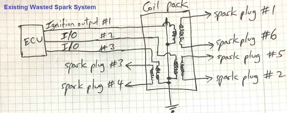
My car has a straight 6 cylinder EFI engine with firing order 1-5-3-6-2-4 (Ford Australia). The ignition setup is a wasted spark type with coils 1 and 6 paired, 2 with 5 and 3 with 4.
I am looking for a circuit that can receive the ignition pulse from the ECU and alternate it between 1 and 6, 5 and 2, 3 and 4.
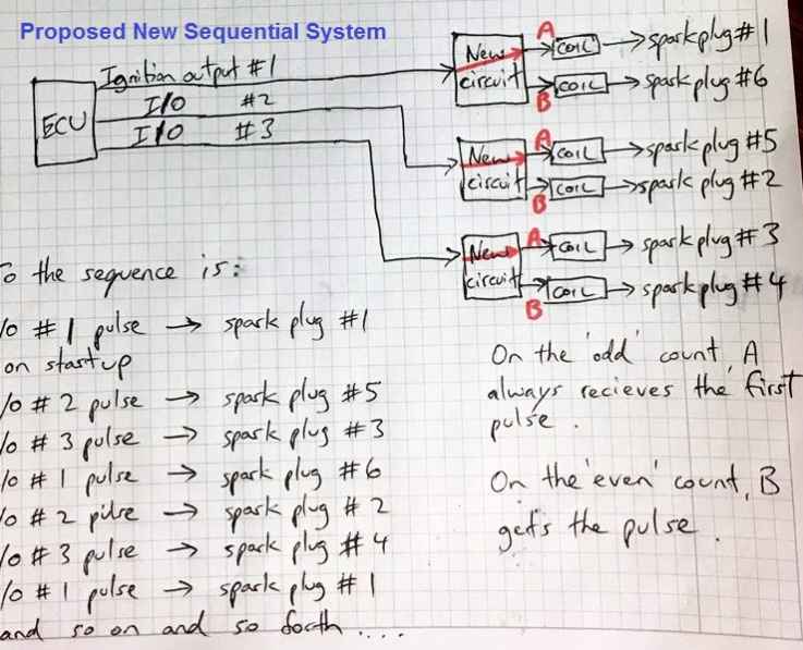
That way you can have separate coil drivers and full sequential ignition. On power up, the system resets, a counter monitors odd and even number pulses, maybe some software will be involved I imagine.
With 3 separate circuits, 1 for each output pulse from the ecu, 1, 5 and 3 always get the first pulse on the odd count and 6, 2 and 4 get the second pulse on the even count. Then the circuit just alternates until you cut the ignition.
I hope you find this project idea interesting and worthy of your time and effort to post a solution on your website.
My Reply: I'll try to design the specified circuit for you, however since I am not an auto expert, I am curious to know how your existing system is a wasted spark type, while the new odd/even idea will help to improve it?
Nevertheless, the new idea can be implemented using ordinary IC 4017 counter divider ICs, according to me, without a software.
Mr. Brenton: I intend to supercharge the engine once the ignition is upgraded with more powerful, individual coils. You are correct, there is no advantage introducing a sequential ignition system on a standard engine.
The three pulses fired from the ECU are in sequence, the timing of which is calculated by the ECU based on engine speed, intake air temp, throttle position etc.
How the Circuit needs to Work
This circuit doesn't need to worry about the working of the ECU. All it needs to do is route the pulse between a pair of terminals to the same terminal first time, then alternate between them.
I'll just put three identical circuits on the one board, one independent circuit per output from the ECU.
What happens is when you first crank over the engine, the ecu waits for a signal from the crankshaft trigger wheel sensor.
Then it waits for a signal from the camshaft position sensor. Once the ECU receives both those signals, it knows where top dead center of cylinder 1 is on the compression stroke.
It then sends out the first pulse as it is programmed to do to fire up the engine and the other pulses follow in sequence.
I’m pleased to hear you think there is a simple solution and I am very grateful that you consider this project worthy of your time.
Please consider the attached sketch for the detailed info.

The Design
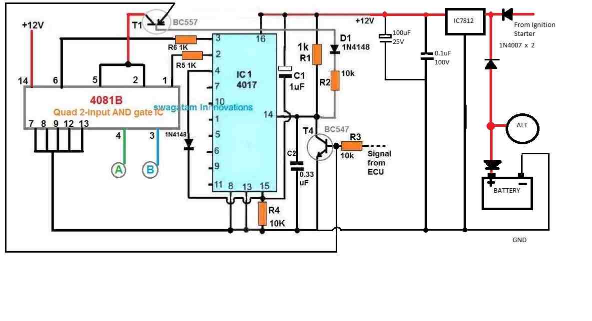
The processor circuit for converting the wasted spark ignition to the enhanced sequential type ignition is shown in the following diagram.
In the diagram points A and B are supposed to be connected to the trigger inputs of the appropriate CDI units, for firing the relevant combustion engines.
The working of the circuit may be understood with the help of the following points:
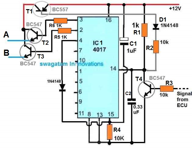
1) As soon as the circuit is powered from the 12V battery, the IC 4017 is reset through C1.
2) Pin3 of the IC now becomes high, and T2 gets into the standby condition with its base biased with the pin3 voltage. But T2 cannot conduct as yet due to the absence of a voltage on its collector pin.
3) When the first ECU pulse arrives at the base of T4, it is turned ON, and T4 grounds pin14 of the IC. But the IC does not respond to this since it is designed to respond only to positive pulses at pin14 and not to negative pulses.
4) However, during the time T4 conducts, T1 is also turned ON, due to its base getting the negative bias via D1, R2, T4. In the process T1 transfers the + 12V to the collector of T2, until the voltage is transferred to its emitter, and to point A
5) Next, the ECU pulse switches OFF, causing T4 to switch OFF, which instantly causes a positive pulse to generate at pin14 via R1.
6) At this point, the IC 4017 responds and causes the logic high from pin3 to jump to pin2.
7) Now, pin2 gets into the standby mode, waiting for the next pulse from the ECU.
8) When the next ECU pulse arrives, the above procedure repeats, until the ECU pulse turns OFF, which in turn causes the logic high from pin2 of the IC to jump to pin4. Simultaneously, the point B is also fired via the emitter of T3.
9) The moment the logic high reaches pin4, the IC gets instantly reset, causing the logic high to return to pin3.
10) The circuit now reaches its earlier position waiting for the next repetition.
We will Need 3 of these Circuits
In the above explained wasted spark to sequential spark ignition converter design, only one example is discussed. We will need 3 such circuit modules to be configured with the appropriate outputs from the ECU, for implementing the proposed enhanced, and highly efficient 6 cylinder engine sequential system.
CORRECTIONS:
The design of the wasted spark switching circuit displayed above seems to have a serous flaw. The emitter leads of the T2, T3 emitter-followers, would be always ON in response to the HIGH logic from the relevant IC 4017 pinouts, rendering the working of the unit completely useless.
The issue can be corrected by incorporating AND gates across the IC 4017 outputs as shown in the following diagram.
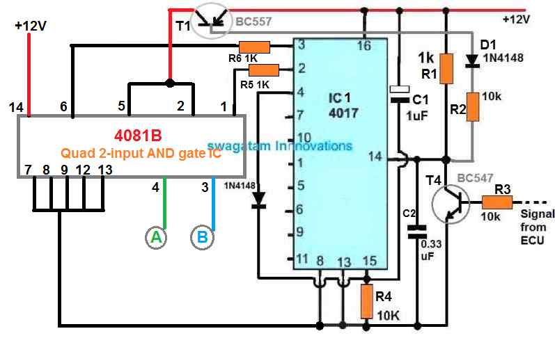
Here we have employed the IC 4081 quad AND gate IC for the switching. Only two AND gates are used out of the 4 gates, the remaining two are not used and appropriately terminated to the ground line.
As an example, if we observe the inputs 1 and 2, we find that 1 is connected to the 4017 output, while the pin2 is connected to T1 collector. The output of this gate is pin3, which is always at logic zero. It will not switch ON or turn HIGH, unless and until, both the input 1 and 2 become high, which can only happen when the T1 switches ON in response to the ECU trigger. The same working can be expected across the input pins 6 and 5, and its output 4.
Test Results
Feedback from Mr Brenton:
Hello Swagatam,
It's been a while since I last contacted you and I hope you and your family are well and safe.
I continued to experiment with the circuit depicted in 'wasted spark2' because it wasn't doing what I wanted. Output A would go high immediately upon powering the circuit. I didn't want this. I wanted output A to wait for the signal from the ECU before going high momentarily to fire the ignition coil. So I finally decided to connect BC557 to the ECU signal line instead of directly to 12V and SUCCESS!
My prototype circuit started working exactly as I wanted.
Due to COVID I have put my project on hold but I am so happy I have a working prototype and I owe it all to you Swagatam. I can't thank you enough.
Stay safe.
Kind regards,Brenton.
The final working prototype of the wasted spark ignition circuit, as suggested by Mr. Brenton can be seen below:
Additional Specifications Provided by Mr. Brenton
- The circuit must lose power if the engine stalls.
- Usually, there is only one big positive terminal on the back of an alternator for power cables to connect to.
- There needs to be a heavy gauge wire connecting this terminal to the battery so that the battery is being charged by the alternator whilst the engine is running.
- When the engine stops, the circuit must lose power and therefore some careful consideration must be given to placement of diodes to control the flow of current.
It won’t work because when you energize CD4917, pin 3 will immediately go to high even though it doesn’t receive a pulse.
We know pin#3 will go high at start, it has been specifically used with this operation in mind.
The last design is a tested one.
Hi, it means that for an inline 4 cyl. two of same circuits must be make? Thx
Sorry, I am not sure about it, hope a knowledgeable reader will be able to guide you on this….
Hello friends, greetings! am lover of electronics and was looking for a system like this, only that did not suit my case, I’m Brazilian and a gentleman developed a similar system, he uses two sensors hall in the distributor, one for the phase sensor, he identifies the PMS cylinder N°1, and the other sensor hall that generate the pulses of the four rotor windows, uses a demultiplexer IC that separates the pulses (split two) a CI Flip Flop with enable input controlled by the phase sensor and thus control the two hall ignition modules and activate two double coils, one for cylinders N°1 and 4 the other coil for cylinders N° 2 and 3. I’m sorry about my bad english, I used the translator. I’ll leave link to the video from which show the operation on the bench. youtu.be/9s0bJ97jcJ4
Hello friends, greetings! am lover of electronics and was looking for a system like this, only that did not suit my case, I’m Brazilian and a gentleman developed a similar system, he uses two sensors hall in the distributor, one for the phase sensor, he identifies the PMS cylinder N°1, and the other sensor hall that generate the pulses of the four rotor windows, uses a demultiplexer IC that separates the pulses (split two) a CI Flip Flop with enable input controlled by the phase sensor and thus control the two hall ignition modules and activate two double coils, one for cylinders N°1 and 4 the other coil for cylinders N° 2 and 3. I’m sorry about my bad english, I used the translator. I’ll leave link to the video from which show the operation on the bench.
Mr Swagatam,
I tried a simulation using the circuit provided. I found that the IC blown up due to 12V supply.
I did not try using the real component yet but my question is the 4017IC can support 12V?
Thank you
Hello Hakim, IC 4017 can tolerate upto 15V, so 12V is perfectly fine for operating these CMOS ICs
I used your circuit as reference and make my own circuit. I tested my circuit on real car. The result is promising.
Below is my experiment information.
The car only have 1 signal from ecu controlling 4 cylinders using old ignition system called distributor.
My goal is to divide the signal from ecu into 4 sequential signal.
The problem I identified are the voltage from the ecu is not 5v eventhough I expect it to be 5v and the output from the AND gate is not 5v so it does not fire the coil on plug.
I tried to use relay LU-5-R but the relay itself need 3v minimum for triggering. Currently I am working to use transistor as relay or switch. I plan to use the signal from AND gate as triggering signal to supply the 5V to the coil. I am still on try and error process.
Wish I can get in touch with you personally and directly to ask your opinion on improving the circuit.
Thank you.
I appreciate your efforts, however due to work load and lack of time it is difficult for me to have direct communication. Moreover, I had designed this circuit long back so I don’t remember its functioning well now.
The signal from the ECU to an old distributor ignition is not 5 or 12 or some positive voltage. The distributor circuit is as follows:
12v from bat, to the ignition coil, from ignition coil to the ECU. So the ECU have internal driver and triggers the ignition coil by switching to ground or open. I am in the same project: I want delete an distributor and go wasted spark or fully sequentiel for an 6 cylinder engine. But you can not copy the above circuit from mister Swagatam, because he invented it to change from wasted spark(ECU gives positive voltage out) to sequentiel. We have to change some parts of this circuit, that the circuit is working with switched ignition signal to the ground.
I am electrician and car enthusiast, but I am not an circuit builder. So if you want to get in touch with me, that we can have a project together, let me know. Greetings.
Mr Swagatam,
Can you please explain the use of C1 and C2 in the circuit?
Also what is the value of voltage rating at C1 and C2?
C1 resets the IC 4017 on power switch ON and ensures that the IC always begins from pin#3
C2 is to safeguard the pin14 of the IC from spikes and transients and avoid false triggering of the IC.
Mr Swagatam,
What is the function of R5 and R6?
Currently I did not put the R5 and R6. What happen is my output of the AND gate is turning on without having to receive 2 input.
Let say output 0 from ic 4017 connected to A1. Signal from ecu connected to B1. Output is C1.
When A1 is on. C1 is on without waiting for B1 signal. Is this because of no R5 and R6?
Hello Hakim, R5 and R6 are actually not required because the input impedance of any CMOS IC will be high, still it is better to use some resistor to avoid voltage spikes and false triggering.
I had designed this circuit long back and I actually don’t remember the working details of the circuit, so I can’t help much with the working of the circuit at this moment of time.
However the circuit was tested successfully by Mr. Brenton, so it should work properly if it is implemented exactly as stated.
Mr Swagatam,
Thanks for your response. Noted that you invented the circuit long ago. I am here because I stuck at the AND gate.
Please go through this slowly.
I already have the two inputs for the AND gate. One is the ecu signal and the other one the signal from sequential circuit 4017.
The problem here if you notice the AND gate consider input A and B always high if not connected to ground. Even when the signal from ic4017 is low. The input at the AND gate still high.
I am contacting you because of the AND gate behaviour. I believe If this problem solved, then the project is success.
Mr. Hakim, to understand your problem I will have to check the IC pinouts in detail and go through the entire design again, which is not possible for me at this moment of time due to lack of time.
The circuit is already a success as it has been thoroughly checked by Mr. Brenton.
Hi Mr Swagatam,
Okay sir. No problem.
Thank you so much.
I will keep update if the result is success.
Have a nice day
Thank you Mr. Hakim, for your understanding!
I do not know the limits of the operation of that integrated my question is if it can work at the RPM of the engine? 5 0 6 thousand rpm
Blame my bad english is from a translator
Swagatam thank you very much for your information.
I have been thinking about a system to eliminate the use of the distributor and only use the rotor as a sensor.
apart from the signal coming from the ecu. another should be taken to determine the TDC of piston one.
I thought about putting a motorcycle hall effect sensor on the distributor cap to determine the PSM. henceforth the circuit will sequence them to the other three pistons.
Thank you Alvaro, I appreciate your response, however I am not an automotive engineer, so I may not be able to provide any useful opinions or solutions in this regard.
I have been doing some tests in proteus with the 4017 circuit, I added some stages to send the signal to the coils, as I upload the image of the circuit, so that you can evaluate it.
I have not been able to put the TDC signal so that the cycle starts at that moment
Sorry, I too seem to have no ideas regarding the Proteus issues, so can’t suggest much.
With the 4017 the circuit will not work because it is barely energized, output 3 will go to high level, I suppose that a circuit is needed that uses the initial pulses of the ECU to turn on this prototype and does not turn on only after start.
It’s a good idea but you have to work on it more, I’m from Venezuela, I’m an electronics technician and how the ignition system of cars works. I will be working on this idea
Hi,
I can see how your circuit works, toggling the ECU signal from one coil to the other, BUT how do you sync it to the motor.
If A is fired first how do you know that A and not B is approaching TDC ready for its power stroke?
The circuit knows when those two cylinders are approaching TDC because of the ECU signal, but doesn’t know which cylinder needs spark.
Tom..
Hi, I think the whole action will get naturally and automatically synchronized once the process starts. I am not an auto expert so I a having difficulty simulating the process correctly in my mind….
The mail I sent before this one, please do ignore, as I’ve carefully re-examined the article and realized that the circuit was doing what it was made to do, and hence it was my flawed expectations that was the problem.
That being said, I would like to ask you to build a circuit that will take a single ignition input signal from the ecu and function just like a wasted spark ignition system with two outputs: a & b, “a” sparks at cylinders 1 & 4, while “b” sparks at cylinders 2 & 3. But in this case it will fire alternately, 1 & 4 first, then 2 & 3. I have sent an article so you can get the theory of wasted spark ignition system operation, to better assist you with this task.
Thanks in advance for your needed assistance.
I will try to figure out the idea suggested by you and possibly post it soon.
Seasons greetings to you n family
As I had indicated to you, I did make this circuit and indeed tried it, however I have an issue: I notice from tests done with my logic probe, that on power up, there’s a constant ground on the outputs a & b, when I turn the key to start, the ignition signal pulse does come, but there’s the issue of pre-ignition taking place. The vehicle does attempt to start, but from all indications, because there’s that constant ground when the key is turned on, but not started, i realize sparks from the coil comes continuously, hence even when on cranking to start there’s no sequence to firing interns of sparks to match the ignition timing, and therefore pre-ignition results.
I checked through my work to ensure there was no mistakes on my part, and all seems to be in order.
So I’m therefore seeking your help.
Also a question: by chance, did you get a feedback from the individual for whom this circuit was made, as in was it a success for him?
Your response and assistance will be greatly appreciated, thanks.
Hello, it seems you are right, the emitter pins of the T3, T4 will be always high, whenever the relevant 4017 output pin is high.
I have tried to correct the issue by replacing the transistorized stages with IC4081 AND gates.
You can check out the updated circuit at the end of the post.
No I did not get any feedback from Mr Brenton, so far.
Will do..thanks again
Hi Nicol,
Do you have any contact? I want to have a conversation with you regarding this project.
Sincerely,
Ok
Well I came to this conclusion based on your explanation of how this particular circuit works. I am an auto technician in jamaica, and I also used to be an electronic tech as well, however, this is an example of a very interesting circuit I’m intent on building and trying out in that regard…I see it’s potential in that area..I’ve been trying for quite a while to come up with a circuit like this: where i use the igniton signal “igt” to trigger a circuit that will give dual or quad ignition output signals to run coilpacks or coil on plug..allowing me to still use my distributor.
I will let you know if it works..thanks again
That sound interesting, I wish you all the best, and do let us know if you succeed with the project!
Good day
Looking at this diagram, and reading the above article, it would appear that this diagram could also be used as a means to operate a waste spark system with a coilpack setup: in that the outputs a could be used to trigger dual coils for cylinders 1 & 4, and b used to trigger 2 & 3. Am I correct in saying so? Your reply will be appreciated thanks.
Thank you for your feedback, I guess it may be possible, however since my expertise in the automobile field is limited, I cannot provide a confirmed opinion on these concepts.