In this post I have explained how to build and use a 18V battery charger circuit for a cordless drill machine. The idea was requested by Mr. Chibuzo.
Technical Specifications
- Here is the issue. I don't have any cordless drill battery charger at all. But I have variable voltage car battery charger.
- I did try to use it by sticking metal plates on the terminal of the battery pack but I found out that the battery pack became warm /hot after a while, so I quickly disconnected it.
- The battery is 18V nicd and I fear if it is not already dead/roasted I might destroy it by pushing in too much current at once using the car battery charger.
- I know you are a very good subject matter expert in this regard, am looking forward to you suggestion. Like I said earlier, am a hobbyist with interest in many areas and I use these tools but getting them charged is an issue for me so am looking for a permanent solution.
- Finally am going to try my hands on as many of your projects I can possibly find parts to handle. Can I personally get across to you if I have problem as I make effort to improve my knowledge of electronics using your platform. Am willing to be your student.
- Thanks for such a large heart as to be willing to share what you know with total strangers. Again, am very sorry to trouble you.
The Design
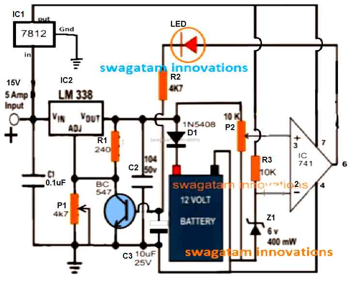
Whether it's a lead acid battery, a Ni-Cd or a Li-ion, this multipurpose battery charger shown below can be applied for any of these for charging them efficiently and without worries:

The salient features of this universal automatic battery charger are:
1) Constant voltage charging
2) Automatic cut-off when battery is fully charged.
3) Max current 5 amps, which means batteries up to 50AH can be charged with this charger normally.
4) Fully customizable as per the battery specs.
5) Low cost
6) No special parts required, all are standard and easily available.
7) LED indicators for cut-off and charging status monitoring.
8) Suitable for garages and home use.
How to set up this simple cordless drill battery charger circuit:
The entire procedure has been comprehensively discussed in this post which explains how to set or adjust an opamp 741 IC based battery charger circuit for implementing an automatic cut-off
The above universal charger circuit is a constant voltage charger and a constant charger when it's implemented as a 5 amp charger, however for lower current charging this circuit might require an additional charging LM338 constant current circuit between the input supply and the above circuit.
Step by Step Setting Up Procedure
- Initially keep the base/emitter of the BC547 shorted.
- Rotate the P2 preset wiper to ground level.
- Without any battery connected, switch ON the input power, and adjust the P1 preset until you get 14.2 V between the cathode of D1 and the ground line.
- Next, adjust the P2 preset, until the LED just illuminates.
- That's all, the setting up procedure is complete.
- Finally, remove the base/emitter short, your cordless battery charger circuit is now ready for the automatic charging and cut off..
How to Charge a 18V cordless drill battery with the shown universal charger circuit
Cordless drill battery can be mostly a Ni-Cd battery which is not as critical as the lead battery counterparts as far as the charging parameters are concerned.
Quite like the Li-ion batts these too will allow you to charge then through a current which may be 1/10th of their AH rating or as high as their specified AH rating.
For example if the drill battery is rated at 3AH, it could be charged at 3/10 = 0.3 amp or 300mA current rate, or any current within 3 amp but not exceeding this limit.
However at the full 1C charging rate the battery could get significantly warm, which must be taken care by an automatic temperature controller circuit or through fan cooling.
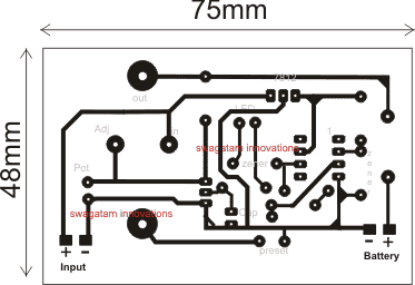
PCB Design for the above explained Cordless drill battery charger circuit

Track side view
Parts List
- Resistors
- All resistors are ¼ watt 5%
- 10K = 1no
- 1K = 1no
- 240 ohms = 1no
- 4k7 or 4.7K = 1no
- 10K preset = 1no at pin#3 of IC 741
- 10K pot = 1no connected with ADJ pin of IC LM338
- Capacitors
- 10uF/25V = 1no
- 0.1uF/50V = 2nos
- Semiconductors
- BC547 = 1no
- IC LM338= 1no
- IC7812 = 1no
- IC 741 or any similar opamp = 1no
- 1N4148 diode = 1no
- 1N5408 diode = 1no
- 6V and 3.3V Zener diodes = 1no each both can be ½ watt rated (can be replaced with 4.7V Zener for both)
How to Build
Power Supply Stage
Make use of a 15V DC source that can provide the LM338 regulator with at least 5A.
Connect the input of the 7812 regulator IC to the 15V supply after soldering it on the PCB. The op-amp and control stages will get a steady 12V from its output.
To make sure the 7812 and LM338 can manage heat dissipation efficiently add a heatsink to each.
Voltage Regulator LM338
In accordance with the circuit schematic, solder the LM338. To modify the charging voltage, use P1 (a 4.7k potentiometer) and R1 (a 240 ohm fixed resistor).
For stabilization of the regulator, solder a 10uF/25V capacitor (C2) at the output and a 0.1uF capacitor (C1) at the input.
For adjusting the output voltage to 19.5V to 20V which is a little higher than the battery voltage, customize P1.
Connection of the Battery
Connect the batterys positive terminal using D1 (1N5408). The reverse current flow from the battery to the charger is stopped by this diode.
Make sure the negative terminal of the battery is firmly attached to the circuit ground.
Circuit for Op-Amp
The 741 IC should be placed on the PCB. To establish the cutoff voltage solder the P2 (10k potentiometer) and R3 (10k resistor) to the voltage divider.
To set the battery's cutoff voltage at about 20V, customize P2.
The transistor (BC547) and LED for charging status indication should be controlled by the op-amp output.
LED indicator
Mount and solder the LED to the BC547's collector using a series resistor (R2, 4.7k). As soon as the battery is completely charged, this LED is going to turn off to show the cutoff state.
Reference to Zener
Mount and solder a 400mW, 6V zener diode (Z1) to give the op-amp a steady reference voltage.
Calibration and Testing
Once the circuit is put together, use a multimeter to check the LM338's output voltage.
P1 and P2 may be gradually adjusted to establish the charging voltage and optimize the cutoff point, respectively.
Before attaching the battery make sure the circuit is working properly by first connecting a fake load, such as a 12V lightbulb.
Calculations
LM338 Output Voltage:
Vout = 1.25 * (1 + R1 / R2) + Iadj * R2R1 = 240 ohms (a fixed resistor).
R2 is adjusted via P1 (4.7k potentiometer).
Iadj is typically very small and so can be neglected for simplicity.
Approximation:
Vout ≈ 1.25 * (1 + 240 / P1_adjusted)Zener Reference Voltage:
Vref = Z1Z1 is the zener voltage (here, 6V).
Cutoff Voltage:
Vcutoff = Vref * (1 + R3 / P2)Vref is set by the zener diode.
Adjust the P2 to set the desired cutoff voltage (e.g., 20V).
Charging Current:
Icharge = (Vout - Vbattery) / RlimitingRlimiting is the resistor in series with the battery (if its used) to limit the current.
