In this post I have explained a few DC motor protection circuit from harmful conditions like over voltage and under voltage situations, over current, overload etc..
DC motor failures are commonly experienced by many of the users, especially in places where the relevant motor is run for many hours a day. Replacing motor parts or the motor itself after a failure can be pretty costly affair, something which nobody appreciates.
A request from one of my followers was made to me regarding solving the above issue, let's hear it from Mr.Gbenga Oyebanji, alias Big Joe.
Technical Specifications
Seeing the harm our power supply has done to most of our electrical appliances, it is necessary to construct a protection module for our appliances that protects them against the fluctuations in power.
The objective of the project is to design and construct a protection module for DC motors. Therefore the aims of the project are
• Design and construct an over voltage protection module for DC motors with indicator (LED).
• Design and construct an under voltage protection module for DC motors with indicator (LED).
• Design and construct a temperature protection module for the motor (Thermistor) with indicator (LED).
The circuit protects the DC motor from over voltage and under voltage. A relay could be used for switching the load (12v dc motor) on and off. A comparator is used to detect if it’s either high or low. The over voltage should be 14V while the under voltage should be 10V.
The necessary rectification and filtering circuit should be constructed also.
When any of the fault is detected the necessary indications should come up.
In addition when the field winding of the motor is open the circuit should be able to detect this and shut the motor down because when the field winding is open there is no longer magnetic flux within the motor and all the power is fed directly to the armature.
This make the motor run until it breaks down. (I hope am right?). I would be grateful to get your response soon.
1) DC Motor Voltage Protection Module Circuit Diagram
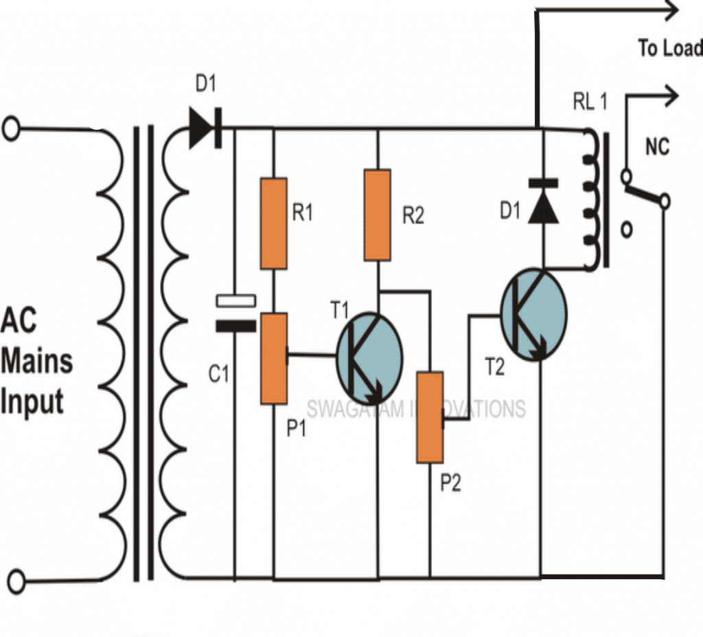
The following high and a low voltage cut off which was earlier discussed by me in one of my posts, perfectly suits the above application for protecting DC motors from high and low voltage conditions.
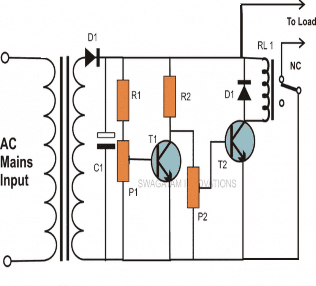
The entire circuit explanation is provided over/under cut-off voltage circuit
2) DC Motor Over Heat Protection Module Circuit
The third problem involving temperature rise of the motor can be solved by integrating the following simple temperature indicator circuit.
This circuit was also covered in one of my earlier posts.
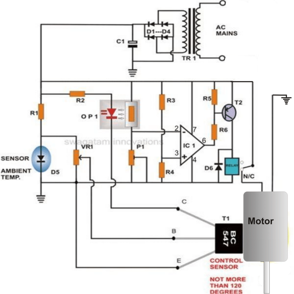
The above over heat protector circuit will presumably never allow the field winding to fail, because any winding will heat up first before fusing. The above circuit will switch OFF the motor if it senses any abnormal heating up of the unit and thus avoid any such mishap.
The entire parts list and circuit explanation is provided HERE
How to Protect Motor from Over Current
The third idea below analyzes an automatic motor current overload controller circuit design. The idea was requested by Mr. Ali.
Technical Specifications
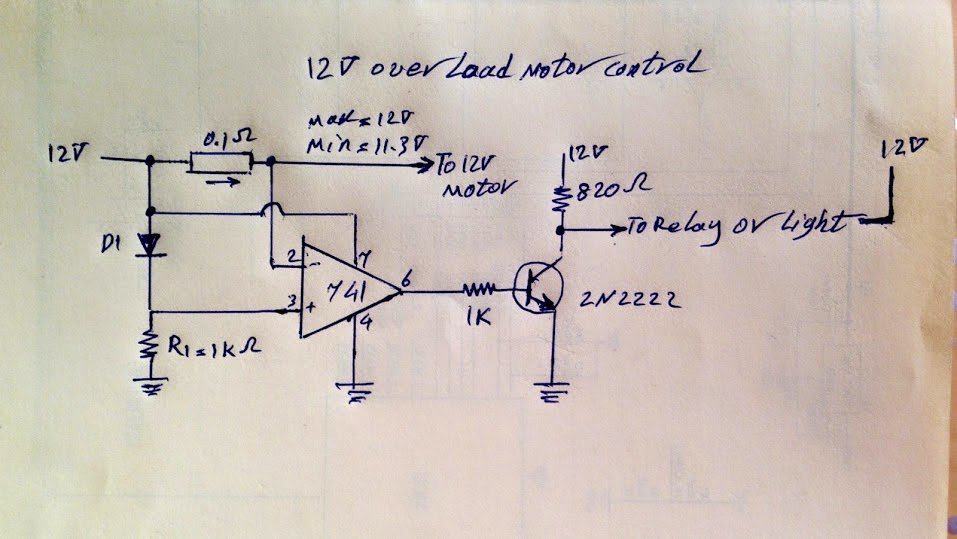
I need some help to complete my project . This is a simple 12 volt motor that needs to be protected when it goes to overload.
The data is shown and can help to design it.
The overload protection circuit should have minimum components because of not enough space to add it .
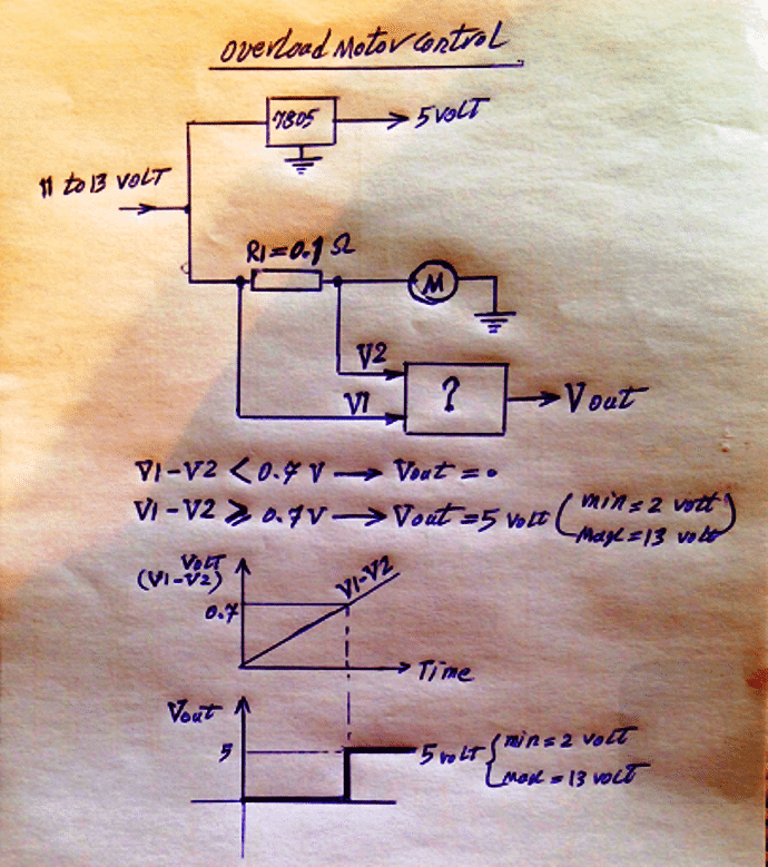
The input voltage is variable from 11 volt to 13 volt because of wiring length but the cut off overload should be happen when the V1 - V2 = > 0.7 volt .
Pls look at the attached overload diagram that should cut off if the amps increase more than 0.7 Amp. What is your idea about this diagram . Is it a complicated circuit or need to be added some components?
Circuit Analysis
Referring to the above drawn 12v motor current control schematics, the concept appears to be correct, however the circuit implementation especially in the second diagram looks incorrect.
Let's analyze the diagrams one by one:
The first diagram explains the basic current control stage calculations using an opamp and a few passive components, and it looks great.
As indicated in the diagram as long as V1 - V2 is less than 0.7V, the output of the opamp is supposed to be zero, and the moment it reaches above the 0.7V, the output is supposed to go high, although this would work with a PNP transistor at the output, not with an NPN, ....anyway let's move ahead.
Here the 0.7 V is with reference to the diode attached to one of the inputs of the opamp, and the idea is simply to ensure that the voltage on this pin exceeds the 0.7V limit so that this pinout potential crosses the other complementing input pin of the op amp resulting in a switch OFF trigger to be generated for the attached motor driver transistor (an NPN transistor as preferred in the design)
However in the second diagram, this condition will not get executed, in fact the circuit will not respond at all, let's see why.
Errors in Second Schematic
In the second diagram when power is switched ON, both the input pins connected across the 0.1 ohm resistor will be subjected to almost an equal amount of voltage.
However, since the non-inverting pin has a dropping diode it will receive a potential that may be 0.7 V lower than the inverting pin2 of the IC.
This will result in the (+) input getting a shade lower voltage than the (-) pin of the IC, which in turn will produce a zero potential at pin6 of the IC right at the onset.
With a zero volts at the output the connected NPN will not be able to initiate and the motor will remain switched OFF.
With the motor shut off there won't be any current drawn by the circuit and no potential difference generated across the sensing resistor. Therefore the circuit will stay dormant with nothing happening.
There's another error in the second diagram, the motor in question will need to be connected across the collector and the positive of the transistor for making the circuit effective, a relay may cause abrupt switching or chattering, and is therefore not required.
Over Current Motor Protection Design
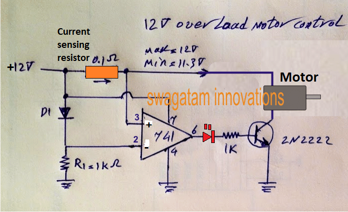
Referring to the above diagram as soon as power is switched ON, pin2 will be subjected to a 0.7V less potential than pin3 of the IC, forcing the output to go high at the onset.
With the output going high will cause the motor to start and gain momentum, and in case the motor tries to draw a current more the the specified value, an equivalent amount potential difference will be generated across the 0.1 ohm resistor.
Now, as this potential begins rising pin3 will start experiencing a falling potential, and when it falls below the pin2 potential, the output will quickly revert to zero, cutting off the base drive for the transistor and switching off the motor instantaneously.
With the motor switched OFF during that instant, the potential across the pins will tend to get normalized and will restore back to the original state, which in turn will switch ON the motor and the situation will keep self-adjusting through a rapid ON/OFF of the driver transistor, maintaining a correct current control over the motor.
Why LED is Added at the Op Amp Output
The LED introduced at the op amp output may basically look just like an ordinary indicator for indicating the over load protection cut off for the motor.
However, it alternately does another crucial function of prohibiting the offset or leakage op amp output from switching ON the transistor permanently.
Around 1 to 2 V can be expected as the offset voltage from any IC 741 which is enough to cause the output transistor to remain switched ON and make the input switching meaningless.
The LED effectively blocks the leakage or the offset from the op amp and enable the transistor and the load to switch correctly as per the input differential changes.
Calculating the Sensing Resistor
The sensing resistor may be calculated as follows:
R = 0.7/current
Here as specified for a 0.7amp current limit for the motor the value of the current sensor resistor R should be
R = 0.7/0.7 = 1 ohm
Motor Protection Circuit with Relay
If at all a relay is preferred, then the above diagram could be corrected and modified as indicated in the following diagram.
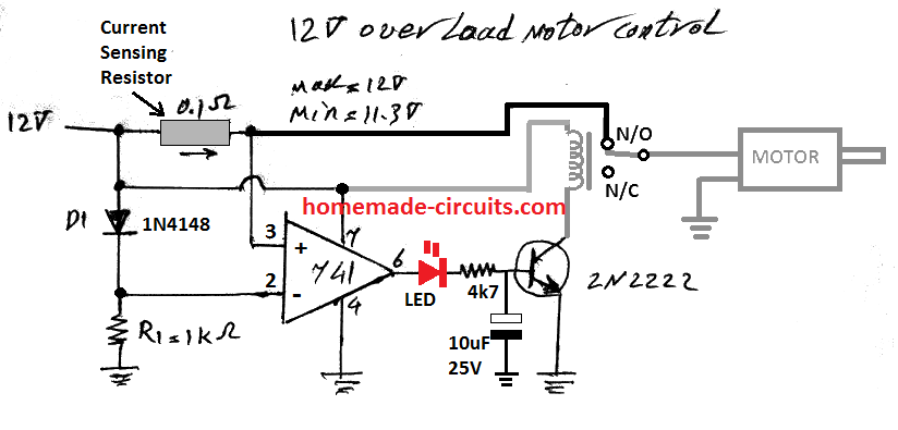
In the above motor protection circuit diagram, the input pins of the op amp can be seen swapped so that the op amp is able to produce a HIGH output at the start and allow the motor actuate.
In case the motor begins drawing high current due to overload, the current sensing resistor will cause a higher negative potential to develop at pin3, lowering pin3 potential than the reference 0.7 V at pin2.
This in turn will revert the op amp output to zero volt switching OFF the relay and the motor, thus protecting the motor from further over current and overload situations.
