A circuit which enables a user to linearly control the speed of a connected motor by rotating an attached potentiometer is called a motor speed controller circuit.
5 easy to build speed controller circuits for DC motors are presented here, first one using MOSFET IRF540, second one using IC 555, the third concept with IC 4093, fourth design involves the IC 741, while the fifth design utilizes IC 556, featuring torque processing
Design#1: Mosfet based DC Motor Speed Controller
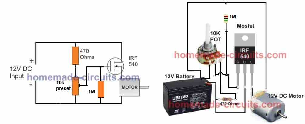
A very cool and easy DC motor speed controller circuit could be build using a just a single mosfet, a resistor, and a pot, as shown below:

Using a BJT Emitter Follower
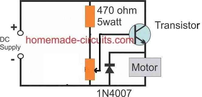
As can be seen the mosfet is rigged as a source follower or a common drain mode, to learn more about this configuration you may refer to this post, which discusses a BJT version, nevertheless the working principle remains the same.
In the above DC motor controller design, the pot adjustment creates a varying potential difference across the gate of the mosfet, and the source pin of the mosfet simply follows the value of this potential difference and adjusts the voltage across the motor accordingly.
It implies that the source will be always 4 or 5V lagging behind the gate voltage and vary up/down with this difference, presenting a varying voltage between 2V and 7V across the motor.
When the gate voltage is around 7V, the source pin will supply the minimum 2V to the motor causing a very slow spin on the motor, and 7V will be available across the source pin when the pot adjustment generates the full 12V across the gate of the mosfet.
Here we can clearly see that the mosfet source pin seems to be "following" the gate and hence the name source follower.
This happens because the difference between the gate and the source pin of the mosfet must be always around 5V, in order to enable the mosfet to conduct optimally.
Anyway, the above configuration helps to enforce a smooth speed control on the motor, and the design could be built quite cheaply.
A BJT could be also used in place of the mosfet, and in fact a BJT would produce a higher control range of about 1V to 12V across the motor.
Video Demo
When it comes to controlling motor speed uniformly and efficiently, a PWM based controller becomes the ideal option, here I have explained more, regarding a simple circuit to implement this operation.
Also Read: High Voltage DC Motor Controller Circuit
Using MOSFET as a High Power Potentiometer
The next figure below shows a very simple DC motor speed controller circuit that employs a MOSFET as a high-power potentiometer (rheostat). The circuit is designed to work with 12 volt DC motors having a peak current usage of below 5 amp.
The mains AC supply is provided through the on/off switch S1 to the primary winding of the isolation and step-down transformer T1.
The push-pull rectifier circuit of D1 and D2 full-wave rectifies T1's output, and the resulting unfiltered DC output is smoothed to a certain extent by C1 to produce a relatively constant DC potential.
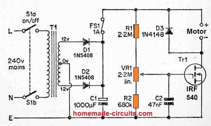
There can be a significant level of ripple on this DC output, however it is unimportant in this application. Tr1 provides power to the load and is biased through a resistive divider circuit consisting of R1, VR1, and R2.
The gate bias voltage provided to Tr1 might not be adequate to allow the MOSFET to conduct meaningfully with the wiper of VR1 at the R2 end of its rotation, and the motor will not operate.
Advancing the wiper of VR1 towards the opposite end of its rotation allows a constantly increasing bias to be supplied to Tr1, resulting in a steadily decreasing drain to source resistance.
Because of this, the power delivered to the motor rises in tandem with the motor's speed, until Tr1 reaches saturation (where the motor runs at its full speed).
VR1 may therefore be used to change the motor's speed from minimum to maximum speed.
C2 filters away any amount of mains hum or other electrical noise that could otherwise be picked up by Tr1's high impedance gate circuit, preventing the motor speed from being reduced to zero.
D3 is a safety diode that inhibits any excessive reverse voltage spikes that may occur as a result of the motor's excessively inductive load.
Design#2: PWM DC Motor Control with IC 555
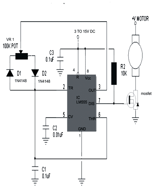
The design of a simple motor speed controller using PWM may be understood as follows:
Initially when the circuit is powered, the trigger pin is in a logic low position since the capacitor C1 is not charged.
The above conditions initiates the oscillation cycle, making the output change to a logic high.
A high output now forces the capacitor to charge via D2.
On reaching a voltage level that's 2/3 of the supply, pin #6 which is the threshold of the IC triggers.
The moment pin #6 triggers, pin #3 and pin #7 reverts to logic low.
With pin #3 at low, C1 yet again begins discharging via D1, and when the voltage across C1 falls below the level that's 1/3 of the supply voltage, pin #3 and pin #7 again become high, causing the cycle to follow and go on repeating.
It is interesting to note that, C1 has two discretely set paths for the process of charging and discharging via the diodes D1, D2 and through the resistance arms set by the pot respectively.
It means the sum of the resistances encountered by C1 while charging and discharging remains the same no matter how the pot is set, therefore the wavelength of the out put pulse always remains the same.
However, since the charging or the discharging time periods depends upon the resistance value encountered in their paths, the pot discretely sets the these time periods as per the its adjustments.
Since the charge and discharge time periods is directly connected with the output duty cycle, it varies according to the adjustment of the pot, giving form to the intended varying PWM pulses at the output.
The average result of the mark/space ratio gives rise to the PWM output which in turn controls the DC speed of the motor.
The PWM pulses are fed to the gate of a mosfet which reacts and controls the connected motor current in response to the setting of the pot.
The current level through the motor decides it speed and thus implements the controlling effect via the pot.
The frequency of the output from the IC may be calculated with the formula:
F = 1.44(VR1*C1)
The mosfet can be selected as per the requirement or the load current.
The circuit diagram of the proposed DC motor speed controller can be seen below:
Prototype Image:
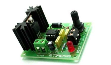
Video Testing Proof:
In the above video clip we can see how the IC 555 based design is used for controlling speed of a DC motor. As you may witness, although the bulb works perfectly in response to the PWMs and varies its intensity from minimum glow to maximum low, the motor does not.
The motor initially does not respond to the narrow PWMs, rather starts with a jerk after the PWMs are adjusted to significantly higher pulse widths.
This does not mean the circuit has problems, it is because the DC motor armature is held between a pair of magnets tightly.
To initiate a start the armature has to jump its rotation across the two poles of the magnet which cannot happen with a slow and gentle movement. It has to initiate with a thrust.
That's exactly why the motor initially requires a higher adjustments for the PWM and once the rotation is initiated the armature gains some kinetic energy and now achieving slower speed becomes feasible through narrower PWMs.
However still, getting the rotation to a barely moving slow status can be impossible because of the same reason as explained above.
I tried my best to improve the response and achieve a slowest possible PWM control by making a few modifications in the first diagram as shown below:
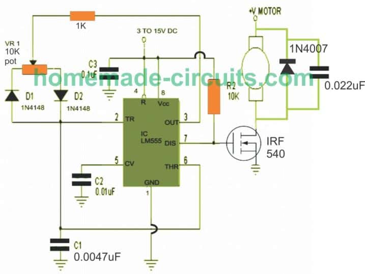
Having said this, the motor could show a better control at the slower levels if the motor is attached or strapped with a load through gears or pulley system.
This may happen because the load will act as a damper and help to provide a controlled movement during the slower speed adjustments.
Another Simple PWM DC Motor Controller Circuit
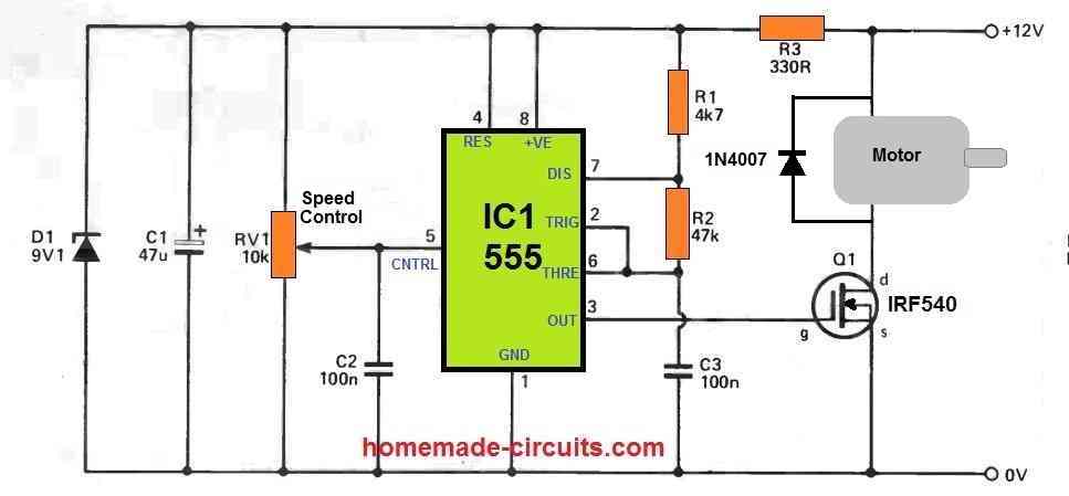
Design#3: DC Motor Controller with Multiple Features
The following DC motor controller circuit provides multiple control features such as:
- PWM Speed Control.
- Direct Speed Without PWM Speed Control (with slow Initialization).
- Forward/Reverse.
- Sudden Brake.
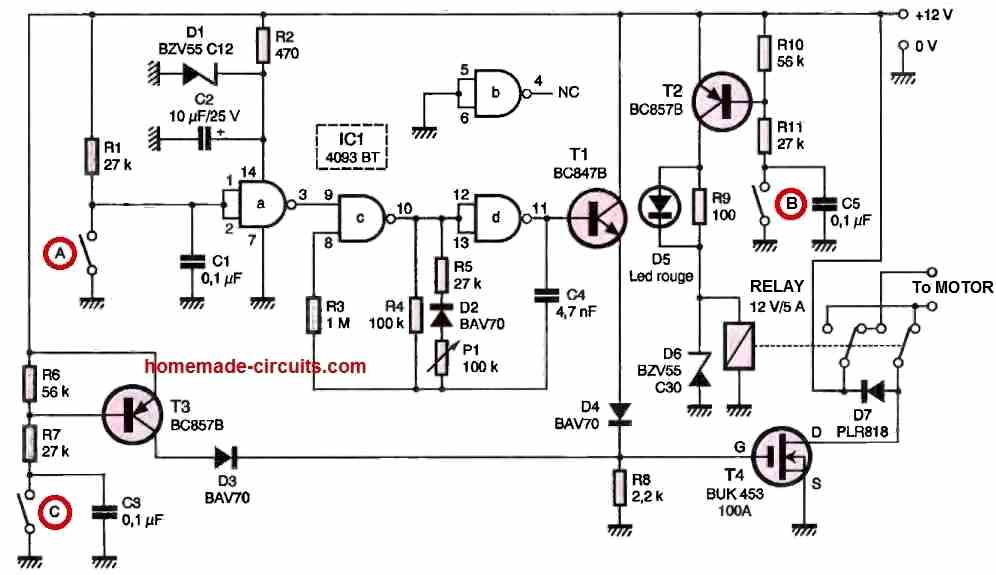
When Switch A is pressed, the PWM function kicks in and the motor speed can be regulated by moving the potentiometer P1.
Pressing Switch B ON or OFF causes the motor to change direction between anticlockwise and clockwise motions. Meaning this switch B can be used to enable reverse/forward motion on the motor.
Regardless of the Switch A position, if Switch C is pressed, causes the motor to attain a direct full speed. In this position the PWM function does not work.
If Switch A and Switch C are both open, then the motor will remain switched OFF.
Design#4: Using a Single Op amp
The op amp circuit described below can be used for regulating the speed and direction of a motor. It functions as a voltage follower, with its positive input (pin #3) linked to potentiometer R3, which functions as a dual-purpose controller for motor speed and direction.
At the mid-point of the potentiometer's range, the op amp output is close to zero, causing neither Q1 nor Q2 to conduct current.
Moving the potentiometer wiper towards the positive side will make the op amp output become positive, allowing Q1 to conduct current to the motor and increase its speed.
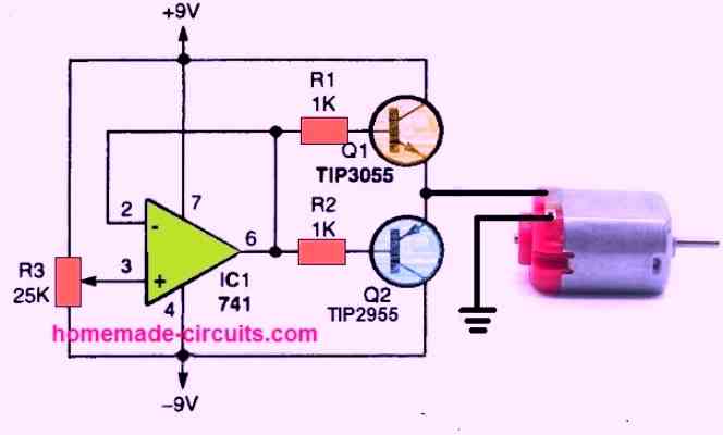
Adjusting the potentiometer towards the negative supply will cause the op amp output to swing to a negative voltage, resulting in Q2 turning on while Q1 is turned off. This action reverses the motor's rotation direction.
Depending on the rotation direction, the motor's speed increases as the potentiometer wiper is pulled towards either end of its range.
To determine the maximum acceptable DC voltage range for the selected motor, it may be necessary to monitor the voltage variation on the emitters of Q1 and Q2.
Design#5: Using IC 556 for Enhanced Speed Control
Varying a DC motor velocity may appear to be not so difficult and you may find plenty of circuits for it.
However these circuits do not guarantee consistent torque levels at lower motor speeds, making the functioning quite inefficient.
Moreover at very low speeds due to insufficient torque, the motor tends to stall.
Another serious drawback is that, there’s no motor reversal feature included with these circuits.
The proposed circuit is completely free from the above shortcomings and is able to generate and sustain high torque levels even at lowest possible speeds.
Circuit Operation
Before I have explained the proposed PWM motor controller circuit, we would also want to learn the simpler alternative which is not so efficient.
Nonetheless, it may be considered reasonably good as long as the load over the motor is not high, and as long as the speed is not reduced to minimum levels.
The figure shows how a single 556 IC can be employed for controlling speed of a connected motor, we won’t go into the details, the only notable drawback of this configuration is that the torque is directly proportional to the speed of the motor.
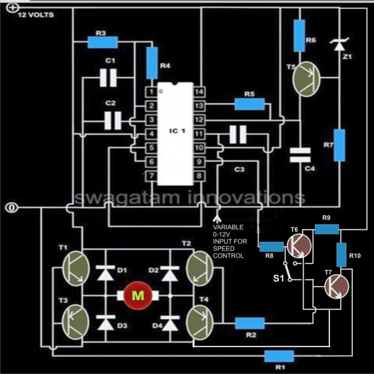
Coming back to the proposed high torque speed controller circuit design, here we have used two 555 ICs instead of one or rather a single IC 556 that contains two 555 ICs in one package.
Circuit Diagram
Main Features
Briefly the proposed DC motor controller includes the following interesting features:
Speed can be varied continuously right from zero to maximum, without stalling.
The torque is never affected by the speed levels and remains constant even at minimum speed levels.
The motor rotation can be flipped or reversed within a fraction of second.
The speed is variable in both the directions of the motor rotation.
The two 555 ICs are assigned with two separate functions. One sections is configures as an astable multivibrator generating 100 Hz square wave clocks which is fed to the preceding 555 section inside the package.
The above frequency is responsible for determining the frequency of the PWM.
The transistor BC 557 is used as a constant current source which keeps the adjoining capacitor at its collector arm charged.
This develops a saw-tooth voltage across the above capacitor, which is compared inside the 556 IC with the sample voltage applied externally over over the shown pin-out.
The sample voltage applies externally can be derived from a simple 0-12V variable voltage power supply circuit.
This varying voltage applied to the 556 IC is used to vary the PWM of the pulses at the output and which eventually is used for the speed regulation of the connected motor.
The switch S1 is used to instantly reverse the motor direction whenever required.
Parts List
- R1, R2, R6 = 1K,
- R3 = 150K,
- R4, R5 = 150 Ohms,
- R7, R8, R9, R10 = 470 Ohms,
- C1 = 0.1uF,
- C2, C3 = 0.01uF,
- C4 = 1uF/25VT1,
- T2 = TIP122,
- T3, T4 = TIP127
- T5 = BC557,
- T6, T7 = BC547,
- D1---D4 = 1N5408,
- Z1 = 4V7 400mW
- IC1 = 556,
- S1 = SPDT toggle switch
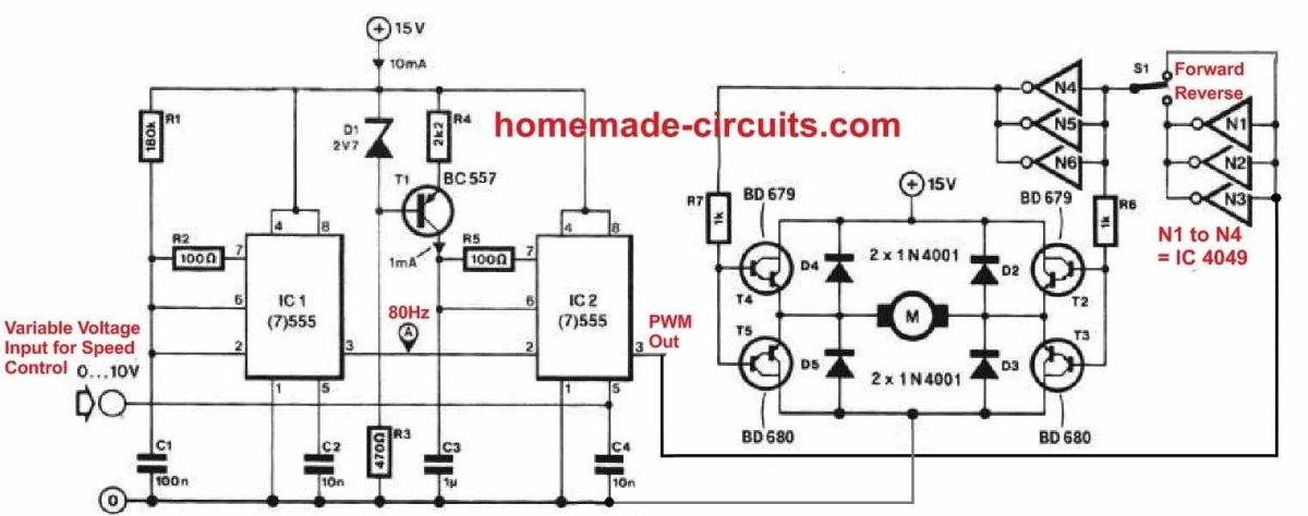
The above circuit was inspired from the following motor driver circuit which was published long back in elecktor electronic India magazine.
Controlling Motor Torque using IC 555
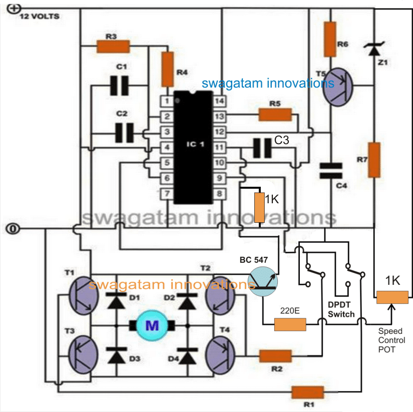
The first motor control diagram can be much simplified by using a DPDT switch for the motor reversal operation, and by using an emitter follower transistor for the speed control implementation, as shown below:
Improved Torque at Low Speed using CMOS PWM Control
Although the single MOSFET linear motor speed controller layouts explained at the beginning of the article includes the benefit of simplicity, but these may have a handful of down sides.
One of them is that there exists a significant level of dissipation in the MOSFET, specifically when the motor is tweaked for approximately 50 percent of the optimum speed.
This may be certainly not a serious issue however, and just requires the installing of a moderately large heatsink on the MOSFET.
A much more critical concern is that the motor is likely to stall as soon as this kind of linear controller is adjusted for any lower speeds.
This is because the MOSFET in this situation has a relatively high resistance, which offers the supply input with a significantly high output impedance.
When the load on the motor is increased, it attempts to draw excessive amounts of supply current, but this leads to a larger voltage drop across the transistor and a lower supply voltage across the motor.
As a result, the power delivered to the motor does not vary significantly, rather it decreases. Due to this, the motor has a propensity to stall.
Also, there is an opposite reaction in which lowering the load on the motor cuts its current drain, resulting in a greater supply voltage and a significant rise in motor speed.
Using a controller that provides a pulsed PWM signal to the motor, you may achieve much better motor speed management.
Improved Torque using CMOS PWM Speed Control
One method of implementing this, and the one employed here, is to have a circuit that provides a fixed output pulse duration while altering the frequency of the pulses to modify the motor speed. A low frequency produces long gaps between pulses and feeds a relatively low power to the motor.
When the frequency is increased, there are no noticeable gaps between the pulses, and the motor receives a nearly constant signal.
This results in a high average power in the motor, which runs at full speed.
The benefit of this system is that when the motor is being pulsed, it is essentially getting the full power during the ON periods of the pulses, and is free to consume a large supply current if the load on the motor actually demands it.
As a result, the motor is powered by a sequence of strong pulses that defy stalling and provide improved torque even at reduced speeds.
The following figure depicts the circuit diagram of a pulsed DC motor speed control. Here, T1, D1, D2, and C1 derive a sufficient DC supply from the mains AC supply.
Tr1 is hooked up in series with the motor, but its gate terminal receives the output signal from an astable multivibrator circuit.
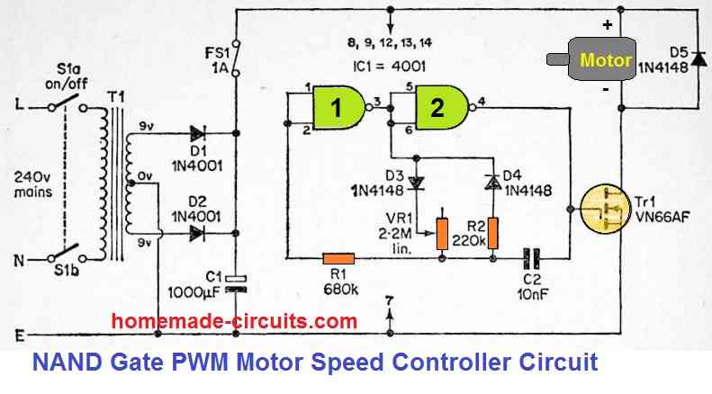
This pwm circuit is built using two of the four gates of a CMOS 4001 device, which are utilized in a CMOS astable setup that is quite a conventional design.
A couple of timing resistors can be seen connected between the output of gate 1 and the junction of R1 and C2, which differs from the conventional PWM design.
VR1 and R2 are the two resistors, along with guiding diodes D3 and D4 connected in series with the output of NAND gate 1.
The two diodes ensure that R2 works like the timing resistance whenever the astable's output is high, and VR1 functions as the timing resistance whenever the output is low.
The period of the output pulses is constant since R2 has a predetermined value. The interval between them could be changed by varying VR1.
This will be nearly zero when it is adjusted for lowest resistance. The output mark space ratio is greater than ten to one at maximum resistance.
VR1, therefore, could be adjusted to generate the desired motor speed with effective torque, with the lowest speed happening at full resistance and the highest speed occurring at zero resistance.
Precision Motor Control using a Single Op Amp
An extremely refined or intricate control of a d.c. motor could be achieved making use of an op-amp and a tacho-generator.
The op-amp is rigged as a voltage sensitive switch. In the circuit demonstrated below, as soon as the output of the tacho-generator is lower than the preset reference voltage the switching transistor be turned ON and 100 % power will be provided to the motor.
Switching action of the op amp would happen in just a couple of millivolts around the reference voltage. You will need a dual power supply, which may be just zener stabilized.
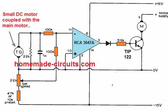
This motor controller enables infinitely adjustable range without involving any form of mechanical hassles.
The op amp output is only +/- 10% of the supply rails level, thus employing a double emitter follower huge motor speeds could be controlled.
The reference voltage could be fixed through thermistors, or an LDR etc.
The experimental set up indicated in the circuit diagram made use of an RCA 3047A op amp, and a 0.25W 6V motor as tacho-generator which generated around 4V at 13000 r.p.m for the intended feedback.
Additional DC Motor Controller Designs:
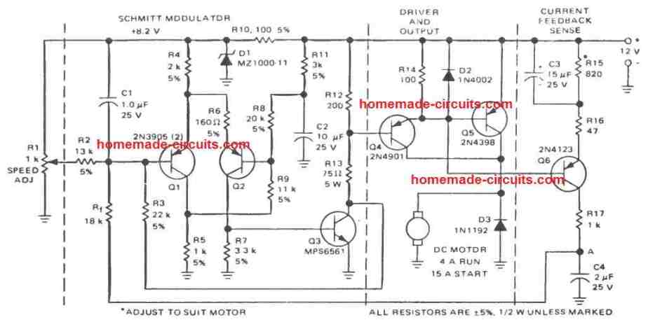
PWM Motor Control using Only BJTs
The following circuit also uses PWM principle for the desired motor speed control, however, it does not depend on any integrated circuits or ICs, rather uses only ordinary BJTs for the implementation. I got this from an old magazine page.
Motor Control Circuits using LM3524
The IC LM3524 is a specialized PWM controller circuit which allows us to configure very useful and precision motor speed control circuits as I have explained below:
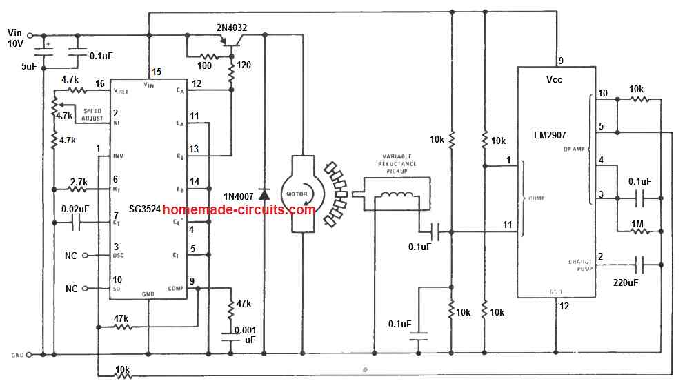
The above diagram shows a basic PWM motor control circuit using the IC LM3524. The design additionally incorporates a sensor based feedback control through the IC LM2907.
A small magnet is attached with the motor shaft, such that during the rotations, the magnet goes past closely to an iron core pickup coil transformer.
The mechanism, causes the rotating magnet to induce a sharp electrical pulse in the pickup coil, which is used by the LM2907 as a trigger input and appropriately processed as the feedback control pulse to the LM3524 IC.
The feedback system ensures that the speed of the once set can never deviate from the set point, providing a precise control of the speed. The pot at pin#2 of the LM3524 is used for controlling the speed of the motor.
Sensorless Control, Without Motor Back EMF
The next LM3525 PWM speed control design allows the feedback control without incorporating a complex tachometer mechanism, or cumbersome sensor arrangements as implemented in the previous design.
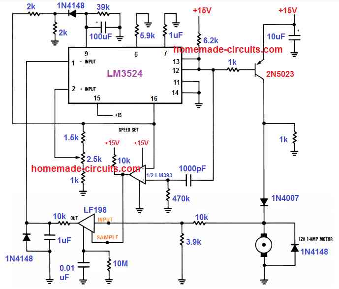
Here, the back EMF from the motor is utilized as the feedback signal and applied to the input of the IC LF198.
In case the speed tends to rise beyond the set level, the LF198 compares the rising EMF signal with the sample reference signal from the LM393 output.
The resulting output is sent to the error amplifier of the IC LM3524 for the necessary processing of the output PWM to the driver transistors.
The controlled PWM due to this sensor-less feedback through the back EMF ultimately enables the motor to remain precisely fixed at a correct speed, as adjusted by the pin#2 potentiometer.
Design a DC motor controller that controls the speed of the motor digitally, using minimum hardware, based on a 2-bit input (S1, S0), and generates appropriate signals to terminals A and B.
Hi Swagatham
Can these motor controllers be short circuit protected in case it’s shorted by a defective motor
Val, yes, we just have to include a current controller stage, here’s an example, in which if we replace the battery with a motor or any load, then it will short circuit protected: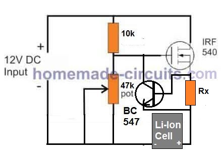
" rel="ugc">
Hi Swagatham
What is the max amps we can go with a simple speed controller using IRFZ44n
Hi Val, It can handle easily upto 25 amps without much heating, and upto 40 amps with a large heatsink.
Hello! Please tell me how to replace the LM3524 chip with SG3525 in a project with sensorless speed control. Can you draw a diagram for this PWM controller?
Vitaly, you will have to compare the pinouts of the two variants and then match the pinouts in the diagram so that both become pin to pin compatible. You can refer to the datasheets of the two ICs for comparing the pinout numbers.
Mr. Swatagam, thanks for the answer! I will try to do as you said, but there is one nuance. I am just a radio amateur and I am trying to understand how the LF198 chip works, what role it plays and how the whole circuit works. Can you write a short explanation of this circuit. I am probably not the only one who is mastering electronics and trying to understand the operation of this or that circuit. Unfortunately, there is very little information about the LF198 chip about its operation in any projects, only dry information from the datasheet. If you can add diagrams (oscillograms) to the explanations, then this will be an excellent lesson on the operation of the LF198 chip.
Thank you Vitaly, for your interesting question…
The LF198 here is simply configured as a sample and hold circuit. It compares the rising back EMF voltage of the motor with the fixed sample reference from the IC LM393 and if it back EMF exceeds this reference level, the LM198 turn ON and shuts off the IC output.
I think you can get a lot of information from the datasheet of this IC.
https://www.ti.com/lit/ds/symlink/lf198-n.pdf?ts=1733192716633&ref_url=https%253A%252F%252Fsearch.brave.com%252F
Mr.Swagatam,
Good morning sir, it had been a long time ,I heard from you. Please I’m having difficulty with circuits for the control of 230 v DC motor speed control ( treadmill motor). Using LM 2917 with interrupters. Please where you able to simulate the circuit diagram before sending to me. And what value of interrupters do you used please I’m want to get results this weekend .
Hello Emmanuel,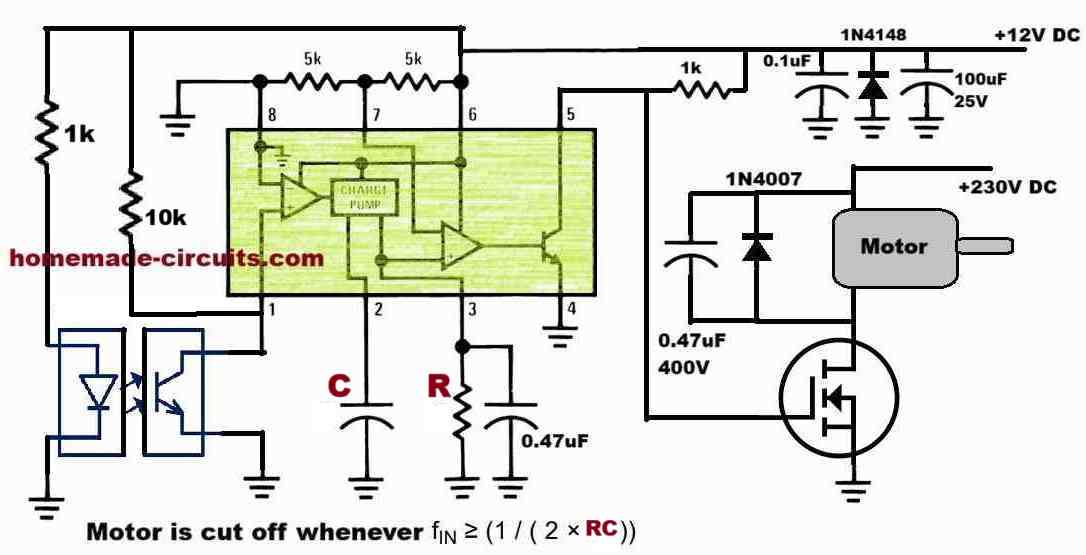
I do not use simulators, instead I use my own brain simulation and datasheet references.
You must check the circuit in a stage wise manner.
In the following diagram, please remove the opto-interrupter and the MOSFET, motor stage completely, and first confirm the working of the LM2917 using a 555 oscillator and an LED at the output.
" rel="ugc">
Feed the 555 frequency to pin#1 of the LM2917 and adjust the 555 frequency until the output LED just illuminates, at the set frequency.
Mr. Swatagam, I have tried the circuit using Led pin 9 of lm2917, it lits but voltage I got is 1.921v ,if to used mosfet , that is will input to the gate. Hope I’m on the right part.
Please check this circuit practically and guide me on the next step . I want this circuit to work by next week please assist me
Hello Emmanuel,
The circuit is taken from the datasheet of the IC, so it cannot be wrong.
I had suggested you to initially verify the design using the following configuration, did you do this?
" rel="ugc">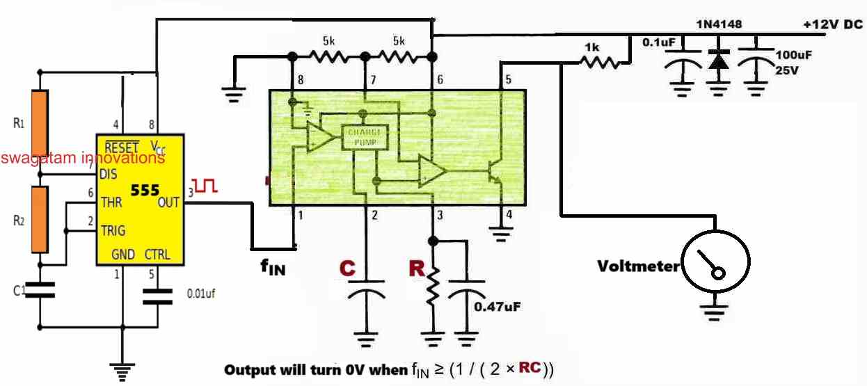
Good morning Mr.Swagatam, I’m here again. I was able to purchase the only available LM2917 with 14 pin assignment, but the configuration of the circuit diagram you gave me is LM2917 with 8 pins. How do I match up the connections with 14pins? Please help.
Emmanuel, In my earlier comment I provided you with the datasheet link of the IC, so you have to open that datasheet and compare the 8 pin version with the 14 pin version, and check the names written beside the pin numbers and match the pins accordingly.
Let me know if you understood the procedure or not?
Thank you ,Mr. Swagatam , I’m unable to see 8 pin of LM2917. I was able to see 14pins of LM2917. Please how do connect the external components to each pins. Please guide me accordingly.
Hi Emmanuel, for an 8 pin version please check the 8 pin diagram, it is shown on page 3 of the datasheet.
Or you can simply use my diagram and connect your IC as per the pinout configuration of the diagram:
" rel="ugc">
Mr. Swagatam,
Yes, I will appreciate which ever design circuit that suit my project: treadmill motor constant speed controller, using LM 2917 and amp 741.
The specifications of the treadmill motor :power/voltage/current.
Thank you so much for time, energy and knowledge put together helping others . Remain blessed.
2Hp, /230vdc, /max 8A
Thank you Emmanuel,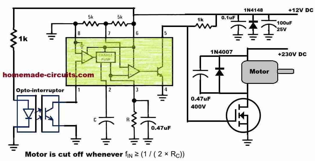
I think the IC 741 is also not needed, the LM2917 alone should be sufficient to keep a constant speed over the treadmill motor.
You can try the following design.
Please select the MOSFET as per the motor specifications, a 400V 20 amp MOSFET should be good enough.
" rel="ugc">
Mr. Swagatam, I’m grateful to you for keeping to your promise.i can see a design built around only LM2917. Please any written note that explain how the circuit works and how to set precision motor speed constant.
You provide a condition formula when the motor would cut – off. Please explain the circuit to me so that I can replicate the same. Thank you sir.
You are welcome Emmanuel,
According to my understanding of LM2917 IC, in the diagram the motor will be turned off whenever the frequency (Hz) of the motor rotation exceeds a certain threshold, which can be fixed by setting up the R, C components, using the following formula:
f = 1/2RC
So, as the mosfet and the motor are cut-off the frequency drops and this reverts the situation so that the motor again turns ON, and rotates until its frequency yet again tries to exceed the threshold, this ON/OFF process keeps repeating, maintaining a constant speed on the motor.
However make sure the value of C is not selected below 500pF.
Mr. Swagatam, thank you for clarification and your time. Well appreciated, I will tried it out and let you know the outcome. Thanks once again
No problem Emmanuel, let me know if you have any practical issues with the design…
Emmanuel, There’s a small error in the opto-interruptor configuration in the previous diagram. Please correct it according to the following updated diagram…
" rel="ugc">
Mr. Swagatam, thank you for updated me on time ,which opto – interrupter should I use? I can use PC817? Pls guide me .
Emmanuel, opto-interrupters are different from opto-couplers, here’s an example of an opto-interrupter: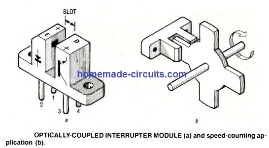
" rel="ugc">
Thank you Mr. Swagatam,
I want to let you know that the LM 2917 which I was able to get has 14 pin out legs ,how do I configured the wiring connections of the 8 pin-out of the same LM2917 on the 14 pin-out ?
I need your guidance pls
Hi Emmanuel,
you will have to check and compare the names designated to the 8 pin version and the 14 pin version, and accordingly do the connections in my suggested circuit application.
You can refer to the following datasheet and check the two versions and compare, to match the pinout designations:
https://www.ti.com/lit/ds/symlink/lm2907-n.pdf?ts=1725853186701&ref_url=https%253A%252F%252Fsearch.brave.com%252F
For example pin#1 in the following diagram is designated as the TACH+, and this is the same for the two ICs, in this way you can go on comparing the other pinouts accordingly.
" rel="ugc">
Wow! Nice post.
I’m interested in pwm DC motor speed control using lm3524 with a sensor based feedback using LM2907.
My question is , can this circuit be modify with opto coupler with the output 3524 to driver 230vdc treadmill motor while IR sensor is being used as feedback using the same ic Lm2907? Please I need your help for modification. Thank you in asvancw
Thanks Emmanuel,
Yes, that’s possible. You can replace the magnetic pickup with an opto-interrupter and get the same results for your 220V tread mill motor. I can definitely help you with this…
Pls thank you for your responses can you help the modification circuit ,here is my email address: [email protected]
Sure, but you will require the IC LM2907 for this project, do you have this IC with you?
Thanks Mr. Swaganta,
I have equivalent of LM2907/ LM2917. Hope I can use it with with IR sensor in place magnetic pickup.
On the pwm control end LM3524, at the output in your diagram ,I will interface opto coupler to enable be control 220Vdc treadmill motor at precision ( constant speed).
Hope , I’m correct any corrections?
Thank you Emmanuel,
Could you please tell me, which equivalent IC are you referring to, because the ICs LM2907/LM2917 are specifically suited and easier to configure with the suggested motor control circuit with the PWM IC LM3524…
Yes, your assumptions are correct.
Mr. Swagatam, Thank you for your commendation on my assumptions. The equivalent to LM 2907 is LM2917. Both are compatible , having the same characteristics.
Thanks Emmanuel, I will design the circuit and let you know, once it is done…
Mr. Swagatam, thank you once for assuring me of modification of this very design . I will looking forward to received it excitement , thank you in advance .
No problem Emmanuel,
Just wanted to share this information, I think your treadmill constant speed circuit can be designed by simply using LM2917 IC and an opamp 741, so the IC Lm3524 is not required.
Let me know if you still want the circuit to be configured usingLM3524?
Hi Mr. Svagatam.
With reference to the circuit with feedback control through the IC LM2907, is it possible to adapt an IR sensor (5v, with LM393) in the place of the magnetic pickup? Thanks in advance, Luca (IT)
Hi Luca,
yes, that is possible.
Hi Sir
I have a small dc motor 3.5volts, I also have 2 pushbuttons switches, one switch is for the selection of speed and the other button is for on/off state.
1selection high speed, 2nd selection mid speed, 3rd selection slow speed, 4th selection pulse, 5fth selection manual.
i want to design a circuit with an IC.
Any options to do this.
Thanks in Advance
Hi Reginal,
the mentioned operations are possible through a single push button, using the IC 4017.
Hello sir, please can I efficiently reduce 5hp 3500rpm to 750rpm speed using pwm circuit? Thanks
Hello Daniel,
PWM cannot be used effectively for an AC motor, instead you can try the phase chopping method using a fan dimmer circuit to reduce RPM.
https://www.homemade-circuits.com/simple-ceiling-fan-regulator-circuit/
No it is DC 5hp motor
In that case, you can try the following circuit, make sure to upgrade the mosfet according to the specifications of your motor…
" rel="ugc">
..also make sure to use separate +positive power lines for the motor and the circuit. use +12V for the circuit, and +240V for the motor. The ground of the two supplies must be connected in common.
Also remember to replace the diode with a 6A4 diode.
Good day Swagatam esteemed and most helpful kind sir,
What are the chances of me using your DC speed controller to control a standard washing machine motor?
The motor is 240V AC, 750rpm 250W and 13500rpm 750W.
It appears to be a normal series connected universal motor with a speed transducer which I don’t need.
I want to use the high speed option to make a router for wood work.
Regards
Andre
Thank you Andre, for your kind words.
Since your motor is a 240V AC motor, I would rather recommend you to use the concepts explained in the following article:
https://www.homemade-circuits.com/simple-ceiling-fan-regulator-circuit/
Let me know if you have any further doubts or questions.
Hi Swagatam, I and trying to design a motor reversing circuit that will be energized when daylight hits an LDR and will run for 2 seconds and then be off until it gets dark, which will cause the motor to be reversed and will run for 2 seconds. I was planning on using a lm358 dual op amp. The op amp would trigger BC548 NPN transistors which would ground the trigger of the C-005 delays to provide the 2 second run time. The C-005 would trigger PNP transistors to feed 5v to the relay coils to energize the relays one at a time (one at dark and the other at daylight).The relays would be wired to reverse the + and – to the motor. I am using a lm7805 to reduce the voltage from 12v to 5v. The NO contacts are connected together and connected to ground. The NC contacts are connected together and will receive power from the PNP transistors (one at dark and the other at daylight).The common contacts are each connected to the motor leads. The circuit is not working as planed. There is not enough power to energize the relays through the PNP transistors. I’ve thought about letting the PNP transistors turn on some added NPN transistors and use those to ground the relay coils. In other words, switch it around where the relays are powered and waiting for a ground. Do you have a similar circuit that might work, or would you be able to design such? Thanks!
Hi Norman,
Which PNP transistor are you using, what is the coil resistance of the relay and how much current the PNP base is receiving? All these factors will be responsible for ensuring the relay switches optimally.
Alternatively you can connect the PNP BJT in Darlington mode to enhance its gain.
Please let me know how it goes.
Thanks for your answer; could you please indicate several equivalent of the PNP 2N5023? In Italy it seems unobtainable.
No problem! You can use 2N2907 or 8550 or BD140 in place of 2N5023.
Last question: no ground for pin #8 of LM3524?
Yes, pin#8 must be connected to ground, it is mistakenly not shown in the diagram…sorry about that.
Hello! Thanks for sharing your projects. I’m starting to learn a lot by reading your site. Regarding the 5.th speed control design (the one using the feedback fem signal), I have doubts with both the LF198 and LM393 connections. Could you please specify the connections using the eight pin numbers wich are reported in the datasheet? Thank you so much, waiting for your answer.
Hello,
For LF198,
INPUT = Pin#3
SAMPLE = Pin#8
The pin that goes to a capacitor is pin#6
OUT = Pin#5
Pin#7 = ground
Pin#1 = +V
Pin#4 = -V
For LM393,
Input(-) = Pin#2
Input(+) = Pin#3
OUTPUT = Pin#1
Pin#8 = VCC
Pin#4 = GND
DESIGN #5
assuming the PWM duty cycle is at 50% then during the high period TR2 and Tr3 will be on and during the low period T1&T4 will be on reversing the current through the motor, Therefore the ave current through the motor will be 0.
Therefore if the PWM duty is less than 50% the motor will reverse since T1& T4 will conduct for a longer period than T2&T4 and if the Duty is greater than 50% the motor direction will be forward as T2&T3 will conduct for a longer period than T1&T4.
Potential problem since for single direction operation the Full PWM duty canot be used
You are right, that seems to be a serious flaw in design#5…
In that case design#3 appears to be a much better option.
Thanks for your reply.
I like your PWM generation circuit using the dual 555 timers so for unipolar operation I will change the full bridge power circuit to a single mosfet as per your design #3.
The motor I have is 24v rated at 15A.
Can you suggest a suitable mosfet that can carry this current
That sounds perfect!
For 24V 15A load, a !RF540N MOSFET should work fine!
" rel="ugc">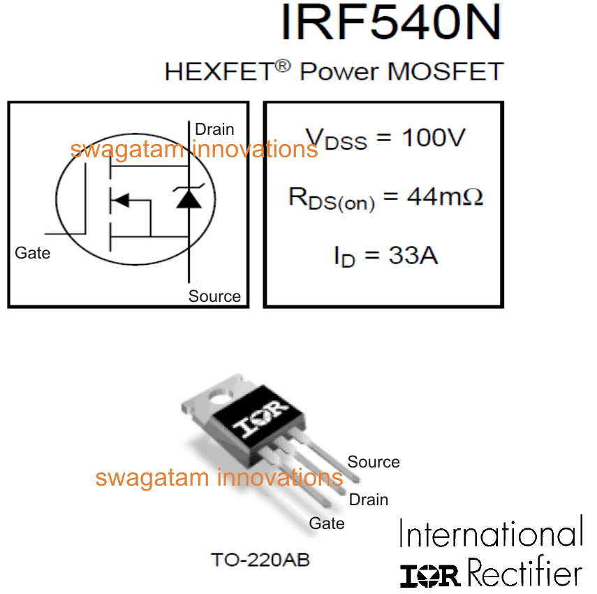
HI could these circuits be implemented on a electrical hanheld screw driver ?
Hi, It is simple, replace the motor with the DC screw driver motor, and replace the power supply with an appropriately rated battery.
Design#3: DC Motor Controller with Multiple Features
Hi,
thanks for this project, how much max current we can give to the motor.
Hi, It depends on the mosfet used for T4. As shown, the BUK453 mosfet can handle upto 100 amps which means the maximum motor current can be anywhere around 50 amps. You can replace this mosfet with any other suitable N channel mosfet.
How to reduce the speed of an electric radio controlled toy car. The car is too fast for the child. I could eventually build an electronic device, and of course not drain the batteries too quickly. Please suggest me a scheme. Thank you.
You can try implementing the following concept, I hope it will do the job for you:
" rel="ugc">
Thank you. I really appreciate your work for the benefit of people.
Thank you Papeca, It’s my pleasure…
Mr. Swagata, I would like to know if the toy car will also go backwards or only forwards with the assembly you proposed.
Hello Papeca, the previous diagram will produce only forward motion for your toy car. For a reverse action you may have to try the following design:
" rel="ugc">
I forgot to specify that the toy car has two engines. One in front and one behind. It also works at 7.2 Volts (rechargeable battery). The problem is starting to become too complicated for me, but I still have hope that you can help me. Thank you.
hello! a project is given to me that says “Design and implement the power electronics kit that provides the variable speed of the motors. The old motor had the power rating, voltage, and current ratings of the motor as follows; 10hp, 220V ac, 38A. The Power supply provided by the KElectric near the plant has 220V, 60Hz ac supply.” now i have to make a new one considering that The plant is located at distant end of the power grid and the power factor goes low during the peak load period, requires a continuity of the power supply at the constant voltage, current and power specs. what do you suggest?
Hello, A triac based speed controller is usually preferred for controlling AC motor speed, which can keep the motor speed at a constant level. However if the input voltage varies then the speed might also vary. I do not have a circuit to ensure a constant current and constant voltage to the motor if the input AC varies.
so do you have a triac based speed controller’s circuit? if yes please send me or refer me to a reference link.
Yes, you can try one of the circuits explained in the following article:
https://www.homemade-circuits.com/how-to-make-simplest-triac-flasher/
Hello,
I need circuit diagram of Closed loop control system for bldc motor with hall effect sensor for the prototype purpose only for my college submission.please provide me circuit diagram with specific components rating marks
Hi, please search “BLDC” using the search box at the top, you may find some good options.
I have started a new way to slot car racings. I am running 540 motors on slot car tracks that power by DC 12-14V. The problem is that the 540 motor burns up the hand controller. Can you help by advising me what to change on the hand controller like by replacing the resistors or thickening the wires etc. Or better yet is there a better design to build a new controller.
540 motor I was told can go up to 200-300W and draws 20-40 amps.
Thank you for your help.
Sincerely,
Ronnie
If 300 W 40 amp is burning the controller then no doubt you will have to upgrade the wires appropriately and also upgrade everything through which this current flows.
Can you kindly point out what size of resistor to start then what size of capacitor? 14 AGW wiring should work if not 12 definitely will do.
Thanks a Million,
Ronnie
If a single resistor is being used for controlling all the 540 motors (300 watt) then its power will need to be around 400 watts, that can be a massive size. The capacitor will not heat up if its voltage rating is sufficiently higher than the supply input voltage. yes 14 or 12 AWG should be quite enough for the wires.
We need a simple closed loop control of dc motor circuit for demonstration for students. please guide me to get a circuit.
Closed loop will require a feedback control loop through the motor’s back EMF which looks a difficult concept, I do not have it at this moment.
Trying to find a circuit similar to that shown for the LM3524 (Back EMF (Whearstone bridge?) speed monitoring, PWM) that also has variable slew-rate limiter. So the truning the speed control fully-up all at once does not result in motor jerking into like, simliarly trune speed control from max to stop does not result in motor jarring to a halt
Sorry, presently I do not have this circuit with me, if I happen to find one, will surely let you know.
Thank you, I can find circuits that contain 2 of the 3 elements (PWM, ‘Feedback’, variable slew-rate limiter) but never all 3
Yes I understand, I hope someone on this forum might be able to help!
I’m trying to make a suitable speed control circuit for a 24v 15a motor which I’m using for a diy drill also as electric screwdriver.
Kindly suggest a good and efficient circuit for it with forward and reverse function.
Using 775 bearing motor
I will recommend you the following circuit. For 15 amp operation you can replace the shown mosfet with a IRF3205.
" rel="ugc">
The forward reverse feature can be implemented with a DPDT switch or with a 4017 flip flop relay circuit
I am enjoying the artices and slowly learning the principles. I am building an electric spinning wheel using a RS550 DC motor . It will be powered by an AC 110 to 12v power supply and/or 12v battery pack. Maintaining smooth speed changes and constistent torque is required. Ability to reverse rotation from a stop is also required. Do you a simple circuit that might fit this.
Thank you, and glad you are learning from this website! I think you should try the following design which is discussed in the above article:
" rel="ugc">
I need to buy a DC Motor Speed Controller for my golf trolley. The problem with most of them, or all of them is that they have pots to control the speed. The pots keep wearing out. Therefore, I would like to have one that goes up and down in speed by the use of a rocker switch. What would that be called? Are they available?
I understand that pots can wear out over time, however we don’t sell ready made kits from this site. Nevertheless I can design a circuit which can be used to regulate the motor speed using a push button. If possible I will try to update the design soon as a new article.
Hello Steve, do you have to have continuously variable speed or would a series of fixed speeds work?
If so the potentiometer could be replaced with a rotary selector switch (much more robust) wired-up with resistances for the fixed speeds. (The only way I can think that the rocker switch could work is to have something like an electronic version of the selector switch where the rocker ‘clicks’ the selector switch up or down a ‘notch’, like the gear change on a Formula1 car!)
Hi, so I have a question about why all DC electric motor controllers on the market are as described above. They all either have variable speed control from very low speed to maximum speed or have 3 fixed speed settings.
My question is, is it possible to build a circuit and program controller that allows for variable speed control in 3 speeds: low, medium, and high. Low being 1-3MPH, Medium being 3-6MPH, and High being 6-12MPH?
Look forward to hearing your response. That was an excellent article you put together, I look forward to making the circuits to get some more hands on experience with control systems and electric motors!
Hi, thanks, and glad you liked the article.
The specifications that you have mentioned can be probably implemented using the following modified design:
Do let me know if you any further questions.
Can this circuit be used on 18v motor
Yes it can be used, but the 18V must be converted to 12V for supplying the ICs
Hi Swagatam, I’m finding your info regarding PWM very helpful for beginners like me. I have been reading and came to this design where you have 3 variabl3 speeds and this is pretty much what I was looking for, but I’m still looking for one more add, not sure if will be possible or f this circuits already does it.
My idea is a ride-on car for a kid that, as he grows up, I can easily change or swap a resistor and therefore increase the top speed. With the diagram you have here I understand I can get that, but can you still use a throttle (potentiometer) in any of the speeds?
So, if the low speed is between 1-3mph, the kid still can ride at 1, 1.5 ,2 or 3 mph, and when he becomes a bit older, in the medium speed he can continue using the throttle to get all the speeds between 3-6mph for example.
Many thanks!
Thank you Jose,
All the circuits above have a potentiometer for adjusting the motor speed. Can you please tell me which schematic are you referring to?
I guess you are trying to have an option where the speed range can be adjusted through a fixed resistor selector and then have a facility to adjust the speed from 0 to max within those fixed ranges. Yes this feature can be included in all of the above designs.
I would recommend the following circuit which looks pretty easy to configure and use:
" rel="ugc">
Thanks.
Sorry I forgot to paste an image of the circuit, but yes, I was talking about this one (" rel="ugc">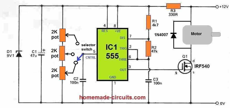 ).
).
As you said, my idea was to have a (or a serie) or fixed resistor and remove them from the circuit as the kid becomes older, so the top speed increases, thus the previous circuit could give me the 3 speed (low/medium/high) and the potentiometer to adjust the speed within any range.
I have been trying this week to do something that I found on the internet but it didn’t work, couldn’t control the speed with the potentiometer. I tested the potentiometer and was working, so the problem was somewhere else.
I’ll give it a go to your circuits after Christmas.
Many thanks!
Great! yes that design should work.
I have improved it further so that only one pot is used, you can see it in the following image. All the best to you.
MAny thanks,
I´ll try this one when I source the components. I’ll try to remember to let you know how it goes
No problem. All the best to you!
Is it possible to vary the the speeds with a single botton. If so can you please give me the circuit diagram. It will be highly appreciated.
It may be possible using an additional 4017 IC with the IC 555. However, the speed adjustment will be UP, UP, UP, then after 10 steps back to zero and then again UP. An up/down sequence at any desired point may not be possible.
First of all thanks for the approval and reply. I am still interested in the use of a single botton to vary the speed of the motor. Can the use of a variable digital resistor in place of the switch be the answer? If so can you please give a circuit diagram. Thanks for all.
Sure, that’s a good idea. I will try to solve it for you, but first please find out which digital potentiometer can you procure for the implementation.
Hi Swagatam,
Thank you for your website! I have quite enjoyed it for a couple of years and I’m sure many people find it equally educational, informative and overall good read.
I’m in need of a suitable speed control circuit. I will be making a mini drill press (for PCB’s) with a 775 motor https://mantech.co.za/ProductInfo.aspx?Item=82M0668
Because it’s a drill I am considering torque for times I might be drilling something else at lower speeds. So was considering your designs: Improved Torque using CMOS PWM Speed Control and Design#3: Using IC 556 for Enhanced Speed Control (Version 3).
I’m limited by my transformer choices as there aren’t a lot available that supports high amps where I stay. They tend to only want to sell ready made PSU’s at insane prices. So I have a 17V 6.2A transformer available.
I think the CMOS PWM circuit will probably be best however in your design you used a half wave bridge rectifier and I don’t know if that’s on purpose (to use both AC cycles). Since I will be powering some other items on the drill and I don’t have a data sheet for the transformer I’d like to stick to a full wave bridge rectifier.
Another concern is that the mosfet in the diagram seems too low for my motor.
Is FS1 a fuse? I would need a larger one, perhaps 7-10A?
Plan is to use the above 17V 6.2A Trf, 8A bridge rectifier, then push it through a LM338 voltage regulator for 12V output. Then in parallel I’ll have a smd led spot 12V (they claim 0.06A), a lm317 to 5V for a laser and at 12V of course the speed control and drill. So there will be 5V & 12V available.
I’m assuming the IC would need to be connected at 5V and the rest at 12V. I’m unsure if the grounds can be connected together. Always hesitant since this is not always the case. Also as mentioned using a full bridge rectifier with voltage regulator. Current mosfet & fuse seems too low.
Could you kindly have a look at my configuration and provide me with a suitable circuit diagram?
Thank you John! Glad you liked the website!
Yes you can try the CMOS speed controller circuit, with a full bridge rectifier input. However please note that this circuit was taken from an old magazine which claims that circuit would provide high torque at lower speeds, I am myself unable to confirm this theory.
Yes FS1 is a fuse.
Another think is that a 6 amp transformer will not be able to provide high torque to a 10 amp motor, so you may have to opt for a 10 to 15 amp transformer.
The IRF540 can handle upto 20 amps so it might be OK, however if you are still concerned you ca use an IRF3205 mosfet.
Please let me know if you have further doubts?
Hi Swagatam.
do you have a circuit diagram speed control for 145 Volt BDC motor ?
the power suply input is 145 Volt from transformer and bridge diode
if you don’t mind please send to my email [email protected]
thanks in advance
Hi Sevoleona, Sorry I do not have a 145V BLDC motor controller circuit with me at this time.
Hi Swagatam
I mean a BDC not a BLDC motor Swa..
I did with 7 paralel MJE13007 and 1 driver transistor MJE 13007, with 50K pot, and 10000uf /250V elco.
when I switch on the circuit, all MJE’s was burn,
if you have time build me a circuit please.
thanks a lot
Hi sevoleona, OK I will try to design it for you soon….
I mean a Brushed DC motor Swagatam.
not a brushless.
thanks
OK, You can try the following design for your 145V BDC motor. You can replace the mosfet with a BJT which must be rated at minimum 200V or higher:
Hi Swag.
it’s me again .
are you use proteus to simulate your design ?
Hi Sevoleona,
I do not use proteus simulation, I simulate it in my mind.
i’m inquiring about using an igbt not a mosfet
Hi Swagatam;
In my circuit I will use also a 4.8 V cordless / rechargeable screwdriver motor. What if I would place 2 or 3 diodes in serial to control the rpm in order to gain slower rpm. Is that same when comparing the above circuits and placing diodes or diodes means not slower rpm but less torque? Kind Regards
Hi Suat,
you can use diodes in series to reduce the voltage to the motor causing its speed to reduce, but the problem is that if the diodes heat up then the motor speed will not be controlled and we cannot add a heatsink to a diode, but we can add a heatsink to a transistor.
With a PWM version the transistor will not heat up as much as it would do in a non pwm version.
thanks too much Swagatam;
However; the motor will be in use for a minute or less duration and the period of the motor usage will be about 3 or 4 times in a day. Then please advise if it is still there is a heating problem may occur?
You are welcome Suat,
It will depend on the diode current rating and the motor current rating. If you are using 1N5402 diodes and the motor current rating is less than 1 amp then the diodes may not heat up too much within a minute.
I tested also 4 pieces of 1N4007 diodes in parallel connected and were remedy on reducing rpm. Start current in a second was about 2 or 1.5 amperes and linear cruise fix current is below 1 ampere. I need your evaluations since I have 1N4007 in my stocks. Best Regards
Diodes actually don’t work correctly in parallel, unless of course they are tightly joined with each other and their leads soldered tightly. If the 4 diodes are not heating up then probably they would drop 0.6V correctly across them, and the drop in voltage will cause a drop in current consumption of the motor
Hi Swagatam;
Referring the first mosfet based diagram;
1- I tested the circuit that only has the parts of IRFZ44N and 22 or 10 K Pot too. I am not sure but as if it was less heating on the mosfet on this circuit than above circuit was (P.S. I also used irfz44 instead of 540 for the above circuit). I will use 12 V and 0.32 A Fan please share your opinion about the matter.
2- Also please advise if it is better for the performance of the fan to use capacitor between the legs of the fan and if so then what should be the value of the capacitor to be used.
Best Regards.
Hi Suat,
For the first mosfet circuit, the mosfet will slightly heat up as the speed is reduced. It will work for both mosfets for IRFZ44N and also for IRF540. If you are finding less heating on IRFZ44N then it is great you can use that mosfet.
Yes adding a capacitor across the motor terminals is good for the motor as reduces spikes and noise. You can typically use any capacitor between 100uF and 470uF, higher the better.
Hello:
I need to control the speed of a 24 volt dc brush motor, only 100 watts, manually but precisely. The input voltage is 24 volt dc through a rectifier, and is not totally smooth. Problem is I know nothing about this stuff.
Do you know anyone who would advise on a project basis, paid of course?
Thank You,
Hi, you can try the following circuit:
" rel="ugc">
You will have to replace the R3 with a 1K resistor for 24V supply.
Although I can provide you the basic instructions, If you are a completely newbie in the field it can be difficult for you to complete the project successfully..
Thank you!!
HI, I need to control the speed of 20 small dc 12v motors together, I mean the ideal is that only one potentiometer control the 20. They only should change speed, Which circuit would be the best for this situation?
Thank you very much for your post!
Hi, you can use the 555 PWM circuit, and connect all the 20 motors in parallel with the MOSFET
Blessings i recently got a 240 outrotor dc motor want to use it on a project, I’m no tech guy so could you simplify your answer (in layman’s terms please)
Thanking you in advance
Hi, sorry I have not yet studied how an outer rotor DC motor works, so won’t be able to provide any helpful suggestions.
Hi,
I am trying to design a motor controller for a brushless dc motor. This will be for an e-bike. I have not decided on a motor yet, but the specs will be something near the following:
Max Power: 3500Watts
Max Current: 85 Amps
Max Volts: 45-50 V
I am planning on using a battery source with about 44 V, and run about 50-60 amps of current.
Which circuit would you recommend, and how would I determine appropriate values for the components? I am a mechanical engineer with limited background in electronics/circuits. I am trying to keep it simple but also learn by experience. I have no experience with PCB design, and am thinking of using a solderable breadboard, do you think this would be sufficient?
Thanks
Hi, the above circuits are intended for permanent magnet Dc motors, not for BLDC motor, so none of these can be used for your application. You will need a specialized BLDC driver circuit such as the following one:
https://www.homemade-circuits.com/50v-3-phase-bldc-motor-driver-circuit/
In case you decide to use a permanent magnet DC motor instead of a BLDC then you can perhaps implement the following concept:
Simple E-Bike Circuit [Electric Bike]
Hello Swagatam,
I am trying to run a 12 V dc 8 amp motor and vary its speed but retain full torque ( no reversing ).
The simplicity of the 555 is attractive but these circuits all need a manual input through the pot and
I want to use a sensor with a zero to 5 V output to vary the speed. All the 555 based PWM ‘s seem to use
both sides of the pot in conjunction with the capacitor to do the timing.
Your schematic using the 556 may do the job as it seems to separate the PMW function ( the
R/Cap relationship) from the method of control (the pot). Is this true? Can this circuit be modified to eliminate the reversing portion? There is a zero to 10 V input shown. Is there a simple way to up my
sensor voltage to peak at 10 rather than 5 ? Can the 5 V be applied to the IC pin and be compensated elsewhere? I know I need a mosfet on the output…any recommendations?
This is asking a lot but the 556 is as close as I’ve come to working unless you have another suggestion
perhaps a different IC entirely.
Any input will be greatly appreciated. Thank you. David
Hi David, you can try the concept shown in the following image. To regulate the PWM using a 0- 5V signal you may have to also change the supply to 5V for the 555 circuits. The R/C network here determines the frequency of the PWM, while the 0 to 5V input determines the PWM output from IC2 at its pin#3
Thank you for your reply. I will need to order some parts
and try to build this circuit.
Sure, no problem!
Swagatam,
How accurate can using the back emf in a closed loop with a pic chip for the PWM and the analogue input for feedback be ?
what sort of percentage deviation from the programmed speed would you expect ?
I presume you take the anolgue input when the output is at the open circuit part of the PWM cycle ?
Hello Chris, Your question is interesting, however My microcontroller knowledge is not good, so it will be difficult for me answer your question.
A bit of research seems to suggest reading the back emf with the analog to digital convertor in between pulses and averaging over a few does the job. Microchip Application Note 893 http://ww1.microchip.com/downloads/en/Appnotes/00000893B.pdf
Hello sir,Regarding the dual 555 / 556 circuit. Is there a way to replace the speed control pot and direction toggle switch with a single device? I am thinking a center detent hall effect thumbwheel. The one problem I see is the output of the HA device is 0 to +5V / 0 to -5V. Could amplify the 5v to 12v required, but how to accomplish the direction change? What if the motor was a small 1.5-6v rated dc motor. Might that be more straightforward in this circuit example.
Hello Joe, I don’t think the circuit can be modified through an analogue circuit. The S1 position cannot be replaced with a circuit, only an SPDT switch or a relay would work in that position.
Hello,
I have a surplus DC treadmill motor that I’d like to build a high speed 4″x48″ belt grinder with. I cannot find any commercially available DC motor speed controllers that can output 240V DC. Will this circuit work for the motor I have? Specs below:
Motor:
Chi Hua Fitness Co MBO-302442BA Out-Rotor DC Motor
240V DC
12 A
3.0 HP
4200 RPM
I have both 120V AC and 240V AC input power available.
Thank you!
It may be possible to control your 240V DC 12 amp treadmill motor using the third concept from the following link, Make sure the mosfet is replaced suitably with a high power power mosfet such as FDA24N40F, and the 555 circuit is powered through a regulated 12V DC.
Treadmill Motor Speed Controller Circuit
Thank you!
Hello,
Looking for advice on the best controller for a battery electric vehicle. Will be using a 1000 watt bldc motor.
Need to design a controller for the motor. This is for a competition and the rules state:
48 Volts nominal or 60 Volts max.
d) If Lithium-based batteries are used, i. Battery Management Systems (BMS) must be tailored to the lithium chemistry to control and protect the battery against risk of fire. 1. The BMS must provide cell balancing and overvoltage protection during off-track charging. 2. For battery electric vehicles, the additional requirement of cell level over-discharge, cell level overcurrent and battery over-temperature must be provided as part of the on-vehicle system. The BMS must AUTOMATICALLY isolate the battery, without operator intervention, if a limit or out of range condition is reached on any of the above parameters. 3. For battery electric vehicles, the on-vehicle BMS must be located in the physical battery package (See Article 57:b)ii above.) ii. For all self-built batteries, the following applies (note: a battery with a separately purchased BMS is also considered a self-built battery). 1. If there are one or more cells or modules, the overcurrent protection value for cells in parallel must be selected such that under normal operating or expected failure conditions, no single cell will be exposed to current beyond its rating. 2. All cells or modules must be identical in configuration. (i.e. a battery constructed from cells of different capacities is not allowed). If the BMS is purchased separate from the battery, ensure it is compatible with battery chemistry. Example: Li-Polymer (LiPo) batteries require a BMS designed for LiPo batteries. iii. Charging of batteries must be done with the battery charger purchased together with the battery or a purpose-built charger specifically suited to the given battery chemistry. For self-built batteries, Teams must demonstrate that the charger is suitable and is integrated with the BMS system. iv. The maximum capacity of any Lithium-based battery used is 1,000 Wh. For batteries not rated in Wh, the Wh rating is calculated by multiplying the amp-hour rating of the battery by its nominal voltage.
e) All batteries and Supercapacitors must be short circuit protected. Protection may be in the form of a fuse, fusible link, or a current interrupting device (circuit breaker). Automatic reclosing current interrupting devices are not allowed. Short circuit protection devices must be located on the positive conductor and as close as possible, or a maximum 300 mm from the positive terminal of the battery or Supercapacitor. The rating of the short circuit protection device must enable the battery or Supercapacitor to always supply enough short circuit current to open the device. For vehicles with a starter motor, the starter motor cable is NOT required to be protected. f) For safety reasons, both the positive and negative circuits of the propulsion battery (for Battery Electric vehicles) and Supercapacitors must be electrically isolated from the vehicle body, frame, and metal components. g) All vehicle electrical circuits must be protected against electrical overload.
The drive train in the Battery Electric category is restricted to a maximum of one electric storage device, and up to two electric motors, with associated control units. The electric motors may be purchased, purchased-and-modified, or purpose-built. Modifications to purchased motor controllers or the use of purchased motor controller evaluation kits are not acceptable. Motor controllers built from sub-components such as single-board computers, power stages, etc. are encouraged.
There are many high quality BLDC diver circuits that you can online…and I would recommend using only those circuits, which are specifically designed for controlling automotive BLDC motors. A few examples can be studied here:
https://www.homemade-circuits.com/?s=BLDC
Thanks for info.
So, which method will all me to use less power on the low setting?
I am looking to run a fan off a battery and run it at a low speed to save battery. The fan I have seems to use a heating element to waste off power to reduce the fan speed, which I assume uses the same power as if on full fan speed.
The PWM circuit in green color is the one that I would recommend for your application.
Hi,
I built this circuit using IC556 and the DPDT switch. It works with a small motor but with the wiper motor, the supply voltage from a car battery drops from 12V to 9V across the motor, drawing 1.5 A and subsequently it barely moves, under no load except for it’s gearbox. This motor draws a no load current of 1.5A if I run it directly from the battery at full voltage. The small motor speeds up and down and changes direction but doesn’t appear to have much torque at low speed. It also needs a bit of ‘winding up’ to start up due to magnetic pull and it appears to already reach full speed halfway through the of travel of the potentiometer.
Please help.
Hi, glad you could build the circuit successfully.
Which transistors did you use for your application?
You can try upgrading the transistors with the following ones, or any other similar equivalent, and see if that helps to increase the output power:
https://www.homemade-circuits.com/50-amp-transistor-mj11032-mj11033-datasheet-pinout/
I used TIP122/127 transistors and beefed up the veroboard tracks expected to carry high current but it turned out as described. I will investigate the availability of the substitutes you suggested. Where I come from everything is not so readily available and the minimum delivery cost makes small packages not viable.
Thanks for your prompt response.
TIP122/127 can get too hot even at 2 amp current making it inefficient for high current application. If you don’t get specialized high current Darlington transistors, you can configure them using pairs of TIP35/2N2222 for NPN, and TIP36/2N2907 for the PNP
Hi Norman, yes PWM circuit will keep things under control and as desired. Please post this question under the following article, I will try to suggest a simple circuit for it:
How to Make a 25 Amp, 1500 watts Heater Controller Circuit
Hi
Thank you for this article. It did help me quite a bit to better understand motor controllers. I am in need of some help reviewing a design of a controller I built for series wound dc motors. I have the schematic and fab files that a friend assisted me with. However my friend abandoned the project and been struggling to find help (since I am visually disabled). I just need a person to help me review the current design and point out errors or suggest improvements. i am in a country with limited PCB and soldering capablity. So have to work with what Iis available.
Thank you in advance for your help, hope this is not off topic.
Hi, I can understand your problem…I really wish I could solve your problem, however it can be difficult for me to troubleshoot a circuit designed by another person, I am sorry about it!
Hi Swagatam.
Thank you for the diagrams, it’s very helpfull.
I have a 12V 2200 watt DC motor that need a controller for 6-14V, can I use one of these controllers? Or should I make some modifications?
Thank you.
Hi Sarjan, definitely you can use the PWM 555 version of the PWM control circuit for your motor, just make sure the MOSFET is correctly rated to handle your motor load.
You can use the 4rth PWM circuit from top, no need of any modifications except the MOSFET, and the motor diode which must be rated higher as per your motor specs.
Hi Swagatam ,
Thank you for your page and work you do!
I implemented design #1 on car blower motor with car battery. It works but mosfet gets very hot very quickly even with radiator.
Why is it heating up so badly?
Thank you Rob, yes the MOSFET will get hot since it is configured as a liner regulator. Putting a large heatsink on the MOSFET is the only remedy to this issue. If you want the transistor to be cooler then you may have to go with the 2nd PWM version of the motor control circuit.
Dear Sir,
Please suggest driving 775 motor for diy electric bycycle. From throttle.
Throttle voltage is 0-5 volt only and supply variable output. Can we feed the output of the throttle by bc 547/8 and then feed to mosfet. Please guide. Email [email protected]
Hello Avisek, you can try the following concept:
https://www.homemade-circuits.com/solar-e-rickshaw-circuit/
The TIP142 can be replaced with an IRf540 MOSFET for increased power handling
SIR
can you provide me a circuit with explanation about motor controls used in industry. my subject is industrial electronics.
thanks
garry luis
Hello Gary, you can refer to the following articles, it may help you to get the required info you are looking for:
https://www.homemade-circuits.com/understanding-scalar-v-f-control-algorithm-for-induction-motor-control/
https://www.homemade-circuits.com/3-phase-induction-motor-speed/
It’s actually a great and helpful piece of info. I am glad that you
shared this helpful information with us. Please keep us
up to date like this. Thank you for sharing.
Glad you liked the post! Thanks for stopping by!
Great, thank you
Hello,
I have a question about design 3.
On Z1 is this a zener diode 4v7 400mW?
It is 2.7V or 3V zener
Hi Swagatam,
Previously l built your Arduino inverter and it works like a charm. I build this Speed controller, it works for small motors like 775, but when l connect to a car radiator fan motor, it blows off probably the if(worked for a few seconds before blowing), any suggestion will be appreciated.
Thanks Rahul, You should first find out the wattage of the motor and then upgrade the MOSFET accordingly. By the way which circuit are you referring to from the above article??
Sir,I want to control an ac motor, any changes to this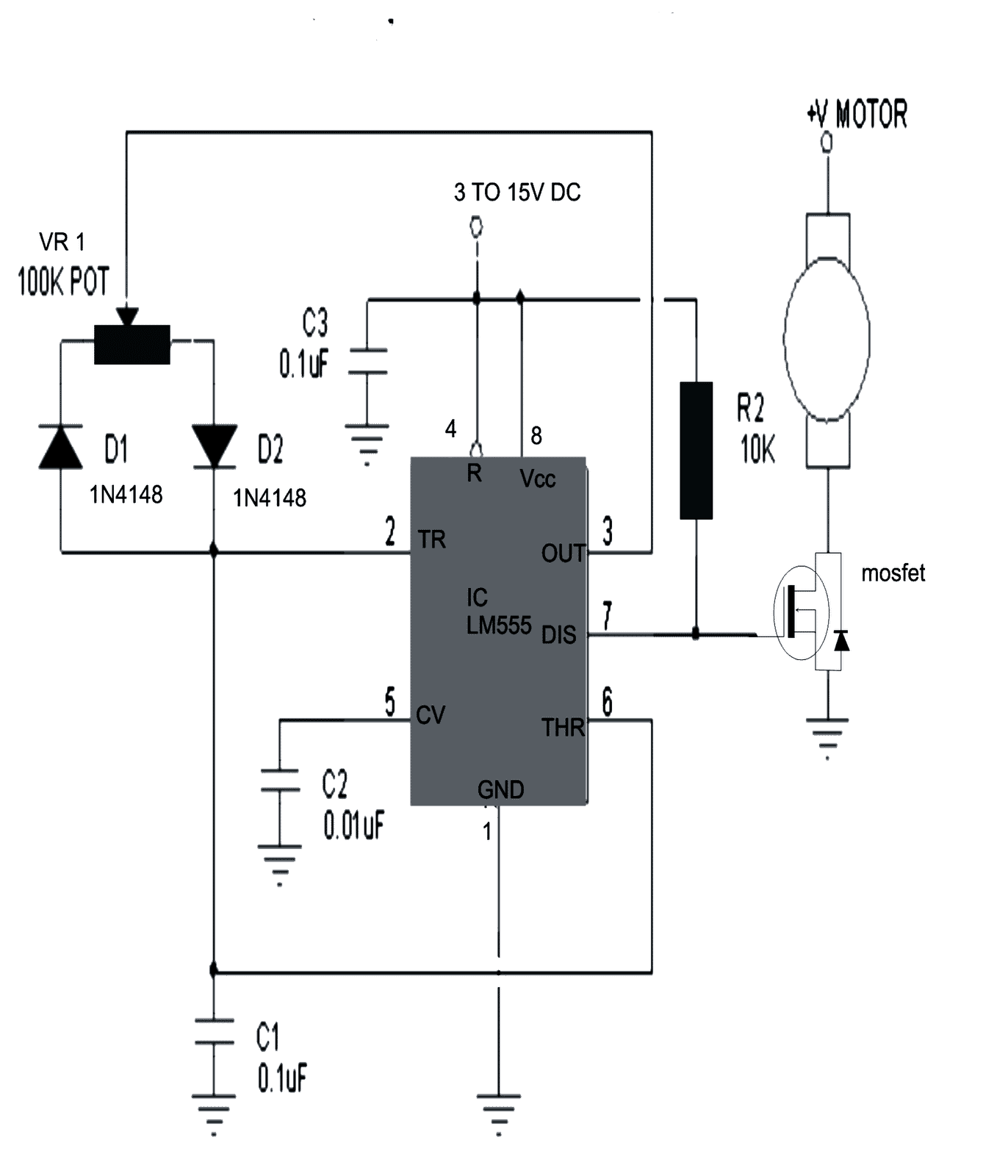
" rel="ugc">
Hello. Thank you for sharing your knowledge.
I made the #2 circuit to drive a 12v 775 DC motor.
The driver works but with two problems:
1. I’m not getting the full speed of the motor. When I connect the motor directly to 12v battery it’s slightly faster.
2. There is a noise in the motor, a loud noise. It’s like Whistling.
Hi,
1. 100% speed cannot be obtained because the max PWM will be always lower than 100%
2. You can try adding a 100uF capacitor right across the motor terminals and check if that reduces the noise.
hello Swagatam, I found your site today, very interesting. May I ask you a small question on the motor control cct using the 555 timer. I wish to control my lawn mower with a slower start up current, because my new LiFeSo4 battery will “trip” with its internal BMS. My mower is a B&D 12v M3300 model. Can you help? Thanks!
Thank you Richard, you can try increasing the C2 value from the shown 0.01uF to 100uF/25V. This should enable the circuit to produce a required slow start or a slow PWM start for your 12V motor.
thanks, you are a great help!
No problem!!
Swagatam, can you help with my problem, i have a treadmill that keeps stop starting – have put it down to the controller board – so i bought myself a 220v to dc speed controller, the machine now works, but the motor sounds very “rumbly” now, quite loud – any ideas, dont realy want to run it as i feel i may do damage – maybe i need to smooth something out – did read that a transformer based controller was needed – but the original circuit doesn’t have this
Hi John, if your motor is also rated at 220V DC then there’s nothing to worry about. To reduce the noise you can try adding a 10uF/400V capacitor right across the motor wires and check the difference.
The capacitor must be a non-polar type or made using 10 nos of 1uF/400V in parallel.
HI Swagatam, Can you help us developing BLDC motor controller for 350/500 W motors rated for 36V
Hi Ganesh, there are plenty of BLDC driver circuits that you can find online or from this site. You can easily follow the steps and build one as per your specifications.
Hi again, Just wondering if you can advise what the components in the bottom circuit are?
1. The blue M sitting inside the diodes
2. Part identified as 220E to the right of the blue M
Thanks
Hi, the blue M in the bottom circuit signifies the MOTOR which is to be controlled. 220E stands for 220 Ohms. All resistors are 1/4 watt 5%
Hi, Design #1 is not a good configuration for the pot.
when the the pot is at or near minimum resistance, the design places the 470Ω across the 12V supply, drawing a current of ~ 25mA for no reason – not great for battery powered projects.
Surely it would be better to use the pot as a potentiometer ?
This could be achieved by removing the connection between -ve and the wiper.
the FET gate would then be connected to the wiper.
Hi, Thanks, that sounds logical, I’ll change the diagram soon.
I assessed your idea but it seems to be one and the same, or may be I didn’t understand your suggestion correctly?
Disconnecting the wiper from the ground and connecting it to the FET gate would also result in wasting 25 mA when the wiper is drawn towards the ground?
Hello Swagatam,
Hope you are well. I made the controller and ran my 220Vdc motor with it successfully. I want to use an IGBT like FGH40N60 insread of MOSFET in my circuit. Can you please guide me how to use it? It will be good if show it in a circuit.
Thanks,
Mah
Hi Mah,
You can do it in this way.
Take BC547 and BC557 transistors.
Connect their emitters together.
Connect collector of BC547 to the positive line, connect the collector of BC557 to negative line.
Join the bases of both the transistor together, and join it with the pin7 of iC 555 and 10k junction.
Now connect the IGBT gate to the emitter junction of the above transistor through a 3.3 or 4.7 ohm resistor.
Connect the IGBT emitter to ground or the negative line, and connect the drain with the motor and supply as done for the MOSFET drain.
Hope this helps.
Hello Swag,
Finally i made the pwm circuit for motor control. I found the IC damaged. I want to know what are differences between pwm circuit with one 555 ic and two 555 ic? Which one is more suitable for a 220vdc 2.2A motor?
I have more questions which i prefer to writethem in thier related topics.
Thanks for all.
Hello Mah,
Actually there’s no difference as far speed control is concerned. But the two 555 design allows you to control the motor through an external voltage source.
Hello Swag,
I used the design#2 to test what i am working on (treadmill motor run using pwm) and find that the voltage of pin 7 is vary between 7.4 ~9 while the pin 3 voltage was from 0.8 to 7.6 by turning pot.
I find mostly in your design that you use pin#3 as pwm output but here in design #2 pin#7 has chosen as pwm output.
Could you clarify me.
Thanks
Mah
Hello Mah, the above design is also another way of implementing an IC 555 astable circuit. The only difference being that the above circuit require a pull up resistor 10K from pin#7, whereas in the other regular design pin#3 doesn’t require any pull up resistor
I want to design a Speed Controller for 1.5HP Permanant Magnet DC Motor…Did you have such Circuit
You can use the above shown designs, just change the MOSfET to match your motor specs.
I am tying to make a 180 volt DC motor Speed Controller by using a SCR Model ACMC 60-1 ACMC100-1 Voltage 220v 600W – 10000W. My input is 120 volts AC. I would like to know how to calculate the size of a Potentiometer to work well.
My other choice is to buy a AC 220 v Motor Speed Controller for DC 0-180 v.
Pease help me out.
Sorry I do not have an SCR circuit, I only have a MOSFET based design. Buying a readymade unit can be a lot easier than making one.
How can I build a DC Motor Controller to operate a 180v dc motor with a 120v ac main input supply?
How can I calculate the size of the potentiometer and SCR?
you can do it by implementing the following concepts:
https://www.homemade-circuits.com/treadmill-motor-speed-controller-circuit/
Hello Swagatam. Thank you for the circuit. I am trying to build this. I got a question about transistors T6 and T7 (BC547). Both the emitters are connected but not driving anything further down. Please explain.
Hi George, yes the the emitters are mistakenly not connected to the ground line. However, I would recommend the last design using DPDT switch, which looks more convincing.
Thank you sir! Appreciate you taking so much effort to answer every question. Such a blessing for learners like me.
I want to connect a 24v /60w motor. So I understand the lower left of the circuit to supply the 24v with common ground. But the bottom right side has a BC547 with 24v into the collector. Question is how to connect the emitter 24v as it cannot be sent back to the 556 IC. Thanks
Hi George, the negative of 24V for the motor and the negative of the 12V for the circuit must be connected in common otherwise the circuit will not work. The BC547 collector can remain connected to the 12V source, only the positive of the transistor bridge network needs to be associated the +24V supply line
Ap kase ho Swagatam Ji,
Thank you so much for your help to us all.
I had built the last two circuits with IC 556, first time it worked but I didn’t noticed much in speed variation. But my major problem now is that it will not even run at all.
The voltage at the 48vdc motor connection reads in millivolts. I don’t know why. The 556 circuit is powered by 12volts dc
I have changed the 1k variable resistor to 10k, 50k, I have also cross checked the circuit many times but still can’t find out why the power reaching th motor is in milli volts.
Bhai ji, if you have a PCB design for it, I will be most grateful to have it.
Sukriya,
Paul
Hi Paul,
Troubleshooting the 556 circuit can be difficult for me, because I am not well versed with the pinouts of 556.
Can you build the circuit again carefully using 2nos IC 555? The IC 555 is easier to understand and can be rectified easily in case of a fault.
And for the present circuit are you using the bridge transistor network or only a single transistor for the motor?
Let me know, so that I can help!
Am using the bridge transistor network. Thanks
Please check whether you are getting the required PWMs at the bases of the transistors, by varying the pot. You can an oscilloscope for this. Or you can a multimeter an check whether the DC level is changing or nt in response to the pot variations.
Hello Swagatam,
I am trying to control a 12V high torque geared dc motor. It spins a disc with couple of kilogram load and required to run at constant torque in 10%-100% duty cycle. I would be using a mobile app to set the motor speed which would be translated by an Arduino into a PWM value to the controller. Therefore your design #3 looks very interesting from constant torque perspective, however since we need to be able to set the speed remotely, is it possible in anyway to replace the mechanical POT with something digital (digital pot?).
I have used commercially available controller with pot and it has worked perfectly with my requirement while the ones that were interfaced digitally with the arduino through PWM would loose troque at lower PWM duty cycle.
Hello Sunil,
Glad you found it useful! You can probability try the circuit presented in the following article, which has a couple of digital pot ideas:
https://www.homemade-circuits.com/digital-potentiometer-circuit-using-ic-2/
Thanks for your very swift reply Swagatam. Could you please let me know if the POT in design#3 can be simply replaced with a digital pot? Are there any voltage/current issues that we need to be aware off? Would there be any impact on the torque behavior? I have already ordered for X9C104 digipots (to experiment replacing the analogue pot in the commercial controller). Could I use it to replace the pot in your circuit?
PS: I am not much of a hardware guy. 🙁
Regards
Sunil
yes you can directly replace the Vh, Vl for the pot end terminals, and Vw for pot wiper, without any issues.
Thanks a lot Swagatam. I will give it a shot and update.
Appreciate your initiative and knowledge sharing! May your tribe increase! 🙂
Regards
Sunil
It’s my pleasure Sunil!
Thank u so much swagatham ji for your immediate reply, I’ll conform and reply u…….
sakthivel
You are welcome!
Just a another follow up question. Is it possible to redesign that circuit in such a way that we can do away with the pot?
Thanks
Sunil
Without pot you can’t adjust the speed, sorry can you please elaborate?
There are dc motor drivers that do not seem to have pots, which makes it simple to use with an arduino. Here is an example that i have used https://robokits.co.in/motor-drives-drivers/dual-dc-motor-driver-20a. However this one looses torque at low speeds.
Thanks
Sunil
If the Arduino allows PWM adjustment through a push button, then the output can be directly integrated with a MOSFET for the required motor control. Do you have this kind of programming for the Arduino?
Good Morning Swagatam,
I am not using push buttons. Currently i am getting the motor speed setting from the mobile app and mapping that to an appropriate pwm value (which ranges from 0-255) and writing it to the pwm pin on the arduino. This pin in turn is connected to the pwm pin off the dc driver from robokits that i mentioned in my earlier post. The only issue i have with that dc driver is that it looses torque at low speeds otherwise it’s all good for my requirements.
Good Morning Sunil,
I meant to say if you are able to control the Arduino by some external means, push button was just an example. So in that case no need of any driver, the varying PWMs can be directly integrated with any MOSFET for getting the required motor control. As far as torque is concerned it will go down proportionately as the PWM become narrower, due to the reduction in the average current.
Hi Swagatam,
Got your point on the push button! Regarding loss of torque at low speeds, isn’t your design #3 meant to overcome this exact issue…i.e lose of torque?
On another note I have used the controller in the below given link and there isn’t any perceptible loss of torque even when the motor is run very slow for eg, 12V 10 rpm motor run at 2rpm still has very good torque. Any idea how is this achieved?
https://www.amazon.in/Phenovo-Controller-6V-90V-Variable-Switch/dp/B07KWPKNGP/ref=sr_1_6?keywords=15A+dc+motor+controller&qid=1561529178&s=gateway&sr=8-6
In summary my requirement is for a controller that retains torque at low speeds, but does not use a pot and can be interfaced and controlled with arduino.
PS: The portal isn’t giving an option to reply to your last message (may be it has reached its maximum nesting?). So sorry the messages may look out of sequence in the conversation thread.
Hi Sunil,
I have practically tried the single IC 555 version and the two IC 555 version, and I found the latter having substantially more torque than the single IC version. It was a long time ago and I did not check the waveform then, so can’t explain the exact reason. However technically it is clear that the output power to the motor will be directly proportional to the fed PWM level. Unless there’s some kind of automatic compensation involved the torque cannot increase.
Yes the comments have a limitation on the maximum number of threads, it’s fine to open a new thread in that case.
Thank you Sunil, I have replied to your email.
Good morning Swagatam Ji.
I am Sakthivel from tuticorin. I want help some handy happed friends to run their try cycles using 500watts universal motor with 24 volt 12Ah battery, for which I need dc motor speed controller circuit ( with IC 555 as a Pulse Width Modulator with reference to your _https://www.brighthubengineering.com/diy-electronics-devices/123681-how-to-make-a-dc-motor-speed-controller-circuit-using-two-555-ics/ )
The above said motor may take normal load current about 21amps and at beak may be 44amps for 10 seconds.
Can you please put a suitable circuit diagram with Parts List and with its values? Post in your http://www.homemade-circuits.com. Also please mention where I have to use Pot meter in the circuit, either in R2 or R4 or somewhere else, because I am diploma mechanical engineer hence I not well versed in electrical and electronic circuit.
My whatsapp no: +91 9092733451
I hope you may post it.
Thank you very much.
Sakthivel.
Good Morning Sakthivel, I think I already have a similar design posted in this website. You can refer to this post:
https://www.homemade-circuits.com/solar-e-rickshaw-circuit/
Please replace the TIP142 transistor with a IRF540 MOSFET for better response
Swagatam Ji,
I am really very much thankful to you for your technical support in building circuits .
Yesterday , I tried with another motor . When I rotated pot from 0 to full , it was amazing experience! I was so happy and thankful to you for your contribution.
Motor was running smoothly , and responding very well to pot rotation.
Earlier when I was doing experiment with smaller motor , it was taking 0.70 amp , when I stopped motor shaft by hand multimeter was showing 0.03 amp . As soon as I release the motor shaft amp reading was 0.70 amp. I was surprised. I thought there must be a inbuilt sensing mechanism in MOSFET . So I asked to you.
Actually multimeter connection was loose and all that happened.
Once again when I conducted same experiment I found it was taking 1.5 amp when stopped and 0.70 when running.
Now, I am running a 650 watt universal motor at 220 volt ac , using a full bridge rectifiers.
At motor terminals volt is 100 volt dc and current value is 1.00 amp when motor is in running condition. When not running volt is 330 and zero amps.
In this condition is it true that motor is using only 100×1.0 = 100 watts only!
Thanks you Swagatam Ji
You are welcome Devendra ji, I am glad you could understand and solve the issue successfully.
yes, if the voltage is 100V across the load, and current is 1 amp, then the effective consumption will be approximately 100 watts.
bro i need a circuit of h bridge that can handle 24v and upto 20amp current . that can control the direction as well as pwm by pins. i realy needs. i have made a circuit but its goes off when about 10amp current flows. 🙁
Abubakar, you can try increasing the transistor rating and check the response. You can try the concept explained in the above article and replace the BJTs with appropriately rated mosfets to handle 20 amp
ACTUALY i am serching a circuit about microcontroler type driver which can be driven by microcontroller . in above we have to control speed by variable pot but i need microcotroler pwm pin to control and very the speed .and i have 24v wheel chair dc moter ..
You can try the following design, however it will require a pot for the controlling
https://www.homemade-circuits.com/high-current-motor-control-using-arduino/
thanks .its recoving my needs so far
Hi Swagatam Ji,
I have to run a 650 watt universal motor, at lower speed .
I am using MOSFET FQPF 4N60 , 555 IC as driver , at 12 v Dc.
10 watt LED is showing very good dimming effect at output.
When I connected 12 volt wiper motor (50 rpm)at output , MOSFET become too much hot within 15 sec time , and motor was running at 4rpm. Pot was at 80% setting.
Mosfet was running very well in 12 v 2amp SMPS power supply.
Motor is running very well at 12 volt and taking only 1 amp.
Would you suggest me how to solve problem-
1.Mosfet heating
2.To get full rpm of motor.
Why not getting trouble in bulb but in motor.
Thanks
Devendar Jakhar
Hello Devendar ji,
did you make the circuit exactly as per the 3rd design in the above article? And did you connect the diode and the capacitor across the motor as suggested in the design? By the way your mosfet rating is not appropriate for the application, because it is rated at 600V, 2.5 amps, please try IRF540 instead and see the response!
For getting full RPM you may have to try the last diagram, using two IC 555, or you can simply try the first design also….
Thanks for reply.
Actually I have to run a universal motor from mains 220 volt. I can’t use traic based controller because of insufficient torque at lower rpm. I think PWM based controller can provide sufficient torque at lower rpm.
Would you please help to modify ready made controller as shown in ‘Prototype’ just above video.
Motor watt 650, 220 volt , Rpm 12000 (1400 at output shaft after gearbox)
Can I use in 4007 for ac to dc conversion, for MOSFET and capacitor based power supply to operate circuit .
Full load current may be up to 5 amp.
Thanks
If it is a DC motor then your existing circuit is correct, but the mosfet is still not correct, because 2.5 amp is not sufficient for your motor, so make sure to use a mosfet which is rated at minimum 10 amps, which should hopefully solve your problem. You can try IRF840 for the mosfet.
for making the bridge you must use a 6A4 diodes, 1N4007 will quickly burn.
Ok.
I will try with IRF 840 .
Thank you Swagatam Ji.
you are welcome!
Good morning Swagatam Ji.
I used K1794 MOSFET for small motor.
Working well .
Motor is 12 volt 1 amp.
At 65 volt dc input motor rpm is 0 to 60.
While at 12 volt dc rpm is only 0 to 5.
How to get full rpm (60) at 12 volt.
When we rotate potentiometer –
What we change frequency or width of pulse of Gate
Volt or amperes at Drain -Source .
When motor is running at full (60) rpm
pot is at 100% , if I stop motor shaft by hand ,
Drain -Source amps will increase or decrease or will be constant ?
Thanks a lot !
Good morning Devendra ji, If you are using the last circuit, then the motor should operate from 0 to full range without issues. Here, we only change the PWM, which decides the ON time and OFF time of the motor very rapidly. If the ON time is high motor rotates fast, and vice versa. At full supply voltage at pin#5 of IC2 the PWMs are maximum wide which allows the motor ON time to be almost permanent, as the voltage at pin#5 is lowered the ON time decreases and OFF time increases and motor average speed also proportionately decreases.
If you try to stop the motor by hand, the drain current will increase and may damage the mosfet, unless the input current is lower than the mosfet current specification.
*motor has low torque and a lever is connected with shaft ,and can be stalled easily by hand at full (60) rpm*
Just add this…
Will there b any problem to my motor if the voltage is 180vdc and i rotate the pot to max 220v. I want to know ur opinion about the 3 circuit u have including the above and the 1 with 2 ic and the 1 wid a 200 turn coil. Which 1 of those will suit my need to control my motor if i use them for a lathe machine. 2motor 1.5hp and 1 thats 2hp. All of them 180vdc. Which circuit will suit if reduce to low speed and the torque will not b sacrifice
You can restrict the pot highest position to 180V. You can do this adding a fixed resistor in series with either D1, or D2 with some trial and error and determine a value which precisely gives 180 V at the output. The output could be checked by connecting a 40 watt bulb instead of the motor.
To set the resistor with one of the diodes the pot should be first moved to one of its extreme ends which produces the max voltage across the bulb, after this the fixed resistor could be added as mentioned above, until the max output is dropped to 180V
Regarding the circuit above can i use a 110v lamp dimmer to replace vr1. Also the other circuit that uses a coil l1 200 turn of 0.6 magnet wire what is the diameter of the iron core to b used. Or can i replace it also with the lamp dimmer and omit the 220k pot
In the above design VR1 is a potentiometer and is a part of the IC 555 circuit, it has no relation to a 110V mains supply, only the motor can be associated with a specified DC high voltage.
I guess you may be referring to some other post.
I’ve made this circuit successfully and it controls the speed of motors and brightness of LEDs.
But I am disappointed with its performance. The difference between the highest and lowest speed limited by this controller is very less. It’s very hard to notice the difference of speed when the POT is lowest and highest. I only noticed difference when plugged a high power 12V LED.
How can I increase the motor speed range with this circuit. I believe one or two components can be altered to increase the difference between highest and lowest speed. I am guessing either C1 or VR1 should be of a different value to do this. Could you please advise? I believe, I am looking for a change in the circuit which will increase the difference between duty cycles of the astable multivibrator output.
If an LED is working with the circuit, that means the circuit is generating the PWMs correctly. The motor could be having troubles due to low current from the source or due to high frequency.
If the problem is due to higher frequency, you can try changing the value of C1 to 1uF and see whether that helps or not.
VR1 is for altering the PWMs and is correctly configured, so it need not be changed
hey guys i am trying to put together something a little different i need to control 12v dc but i need to have and adjustable soft start(start at 30% or 50% ect.) possibly adjustable freq and adjustable max speed with amp draw of about 20 amps is this something feasible
Hi Jose, you can try the concept presented in the first diagram of this article
https://www.homemade-circuits.com/pwm-motor-soft-start-circuit/
use a 1k pot for R9 to get an adjustable soft start facility, and make sure to use a Darlington transistor for T2 for an effective soft start control.
R1 can be used for frequency control
What would adjust the time it takes from start to max duty cycle
it can be adjusted by replacing the base resistor of BC547 with a variable 10k pot, in the linked circuit
I will let u know how it goes
ok!
Hi sir, I have tried make a transistor pwm controlled speed controller own my own, so please check the link and tell me whether the circuit will work or not. (Already done ic version and it was working good) Please suggest corrections or suggestions. https://plus.google.com/+AbhishekSharmatechperson/posts/UNawNfrQpW4
yes it will work…no need to use R5, for better results connect the mosfet gate directly with astable input
Hi, it Works with a motor 24 V 3 A??
Hi, it can be used for 24V 3 amp or any other power rating, since the motor supply is isolated from the circuit supply.
Where do I connect the negative supply from the motor? The motor is 48Volt dc. I assume I connect it to the negative rial off the circuit.
connect all the negatives in common.
Thank you. You dont perhaps have a circuit for a 4 wire 48v dc fan, or can i just connect pin 7 directly to the yellow PWM controle wire?
sorry this circuit will work only with two wire motors, for a BLDC motor you may have to use a BLDC driver circuit, I have many such circuits in this website…
Thank You..
Hey People. I want to use the circuit to dim 6x100w 36v dc LED chips. what mosfet must i use and what diode do i need. the power supply 12v dc to dc 36v convertor
you can use IRF540 on a large heatsink, diode won’t be required since LED is not an inductive load.
feed the 12V to the IC circuit and 36V to the LED. The motor should be replaced with the LeDs….
Hey swag
Can I drive 4 IRF540 mosfet on pin 7 of the 555 pwm. I have 4 side on the LED bar that I want to dim
the Front will have 6 x 100w LEDs
Back, left and right will only have 3 x 300w LEDs
hey Gysie, that means the total wattage of the LED is 1500watts, can you specify the voltage rating of the respective LeDs, this will allow us to calculate whether IRF540 could be suitable or not….
hey swag.
one led is 100w at 32-36 volt I will be running a max of 9 Led on one dimmer. And a max of 6 on the other dimmer. what about connecting the leds in series?
Kind Regards
Hi Gysie, yes you can connect them in series and limit the current requirement to 3 amps, however from where do you intend to get the voltage source for driving these LEDs, is it from mains 220V directly? and how do you plan to control current for these LEDs? please specify these parameters, it will help me to suggest the most appropriate configuration.
[20:57, 9/9/2017] +27 63 773 1688: Hi Swag,
These led are going to be use on a harvester operating at 12vdc.
I am planning to use the dc-to-dc with the following spec
Input voltage:12V-60V
Input Current:Maximum input current of 15A
Output voltage:12V -80V continuously adjustable
Output current:maximum output current of 10A ( adjustable )
Output power:the effective power P = input voltage V * 10A
Conversion efficiency:up to 95% ( input voltage, current; output voltage and current impact of conversion efficiency )
Short circuit protection:Fuse
Size:85*60mm
Quantity:1pc
The harvester needs 6 LED in front I was thinking of connecting them in parallel.
then 3 LEDS on the left side, 3 on the right side and 3 on the back.
I have no problem building multiple dimmer, if you can only help me out with the right amount of led bulbs per mosfet and what mosfet. I can really afford burning out bulbs, it takes about 3 months to get them where…
Specification(20W/30W/50W/100W)
Model Type: High Power Integrated Chip lamp Beads
Chip size: 24MIL*44MIL
Forward Voltage: 30-36V
Forward current: 100w(3000mA)
Luminous Flux: 90-120LM/W
Color-rendering index: 60-85
Beam Angle: 120 degrees
Working Temperature: -20 centigrade to 60 centigrade
Color Temperature: Warm White: 3000-3200K
White: 6000-6500K
Lamp Body Material : Pure Copper Bracket
Life Span: 100,000 Hours
[20:57, 9/9/2017] +27 63 773 1688: dan brand hulle
[21:14, 9/9/2017] +27 63 773 1688: Hi Swag,
What mosfet do I need to be able to dim 3 of these LeDs connected in parallel at 36vdc?
These led are going to be use on a harvester operating at 12vdc.
I am planning on using dc-to-dc converters with the following specs:
Input voltage:12V-60V
Input Current:Maximum input current of 15A
Output voltage:12V -80V continuously adjustable
Output current:maximum output current of 10A ( adjustable )
Output power:the effective power P = input voltage V * 10A
Conversion efficiency:up to 95% ( input voltage, current; output voltage and current impact of conversion efficiency )
Short circuit protection:Fuse
Size:85*60mm
Quantity:1pc
The harvester needs 6 LED in front I was thinking of connecting them in parallel.
then 3 LEDS on the left side, 3 on the right side and 3 on the back.
Specification(20W/30W/50W/100W)
Model Type: High Power Integrated Chip lamp Beads
Chip size: 24MIL*44MIL
Forward Voltage: 30-36V
Forward current: 100w(3000mA)
Luminous Flux: 90-120LM/W
Color-rendering index: 60-85
Beam Angle: 120 degrees
Working Temperature: -20 centigrade to 60 centigrade
Color Temperature: Warm White: 3000-3200K
White: 6000-6500K
Lamp Body Material : Pure Copper Bracket
Life Span: 100,000 Hours
Kind Regards
Gysie
And thanks a lot for all you help.
Hi Gysie, I’ll explain briefly how to quickly calculate the mosfet ratings for your specific LEDs. If we take the example of IRF540, its max current handling capacity (with optimal heatsinking) is around 25 amps, and voltage is 100V.
The voltage looks definitely well above the specifications of your LeDs and the input supply level, so we can ignore this parameter. and concentrate on the current specs. You just have yo ensure that if the LeDs are connected in parallel with this mosfet the total current (sum) of the LEDs must not exceed the 25 amp limit. If it does then you can simply add another IRF540 in parallel with the existing one, which will instantly raise the capacity of the system to 50 amps, and so on.
In this way you can yourself adjust and optimize the mosfets with the LeDs in order get the prefect match across the selected dimmers.
I hope this will help you to understand and optimize your design
Hi Swag.
I only have this last question. Connecting IRF540 in parallel like?
drain-to-drain
Gate-to-gate to pin7(DIS) on the 555 pwm ciruit
source-to-source
Kind Regards
Gysie.
thanks for your time in helping me
Thanks Gysie, yes you can connect drain with drain, source with source and for the gates connect their resistor ends in parallel.
Hey Swag,
Can what resistor do I need? and will it go from
pin 7 – gate1
pin 7 – gate 2
and so on
Kind Regards
Gysie
Hi Gysie, yes that’s right, join the ends of all the gate resistors together, and join this common point with pin#7
Hi sir, is putting a freewheel diode across mosfet necessary as flyback from motor can damage mosfet, and what can I do if I don't have a freewheel diode, can I use make freewheel using 1N4007 and 1n4148 in combination if yes then how?
Hi Abhishek, the value of the diode will depend on the motor current, if it is a low current type motor not above 3 amps, then a 1N4007 can be used…..combination of parallel diodes may not work correctly.
however today all mosfets have built in freewheeling diodes.
Hi sir,
https://plus.google.com/+AbhishekSharmatechperson/posts/a4fZ5tRkS7Y I have made circuit in link it's working good but speed is not controllable I have tried to adjust the 100k preset many times. Speed is always constant. This is circuit in link https://plus.google.com/+AbhishekSharmatechperson/posts/a4fZ5tRkS7Y I have use tip 122.
Hi Abhishek, it will be difficult for me to troubleshoot a fault in your circuit without practically checking it…the above design is a fully tested and confirmed design, and it is a standard PWM circuit so it cannot be wrong.
you can do one thing, connect an LED across pin#7 and ground, and check its brightness in response to the pot adjustment, if it varies then your IC 555 section is good
Hi sir, I have not used above circuit I used circuit in link I'm giving under and one more thing in my diagram I have wrongly positioned diode 1N4007 but in reality it's correct. Please refer to link https://plus.google.com/+AbhishekSharmatechperson/posts/a4fZ5tRkS7Y I have use tip 122.
I'm taking output from pin 3
OK, then connect an LED from pin#3 to ground with a 1K resistor in series…and check the illumination by adjusting the pot….
Hi sir swagatam, bravo, I modified circuit as same shown above and it's perfectly working, now speed is also controllable, thanks for your guidance. New question, I had not added 1N4007 to irf540, so now should I add it and it's not operating 12vdc 775 motor general purpose pcb drill motor, it's 15w. I'm using two 9v battery.
That's great Aabhishek, however your previous circuit is also correct and should have worked…investigate why it did not work.
it is better to add the 1N4007 diode for ensuring 100% safety to the mosfet.
9V PP3 can be used only for very low current applications, motors will never work with these batts, you should use a bigger battery or many AAA 1.5V cells together
Hi sir, through 9v small motors are perfectly working but the 12v 775 motor (15w)not even move. All other motors are perfectly working. Should I use 12v 7.6ah lead acid battery, are you sure 7.6ah lead acid battery will not burn the circuit or ic
Hi Abhishek, even a small motor will quickly drain your 9V battery, so it is not recommended for motors.
you can use 7.5AH batt, it will not harm the motor as long the voltage is correctly matched.
Well done sir, but how can I use MOSFETs IRFP064 to drive a 100V, 10A DC motor on the above circuit, thanks
Thanks kakooza, you can use it in the same way as shown in the diagram.
Hey swagatam , can I use this circuit to power a 3V or 6V DC motor that I will use to drive a small remote controlled(wired) toy?
Hey Arpan, yes definitely you can do it without any issues…
sir——–i have 35 v load needs 3.3 A current—-around 120 w—–i am providing 12 v dc separately to 555——-
——my doubts are
1——- should i connect 35-0 v dc directly to motor +ve terminal and neutral wire to other side as shown——figure
2—–approx weight size of heatsink for 200 watts for mosfet
3—–i have 10 k pot will that be ok
4———-1 kohm of ??? watts resistor should be connected wiper of pot and 3 pin —prevent pot from burning———–i have a doubt
5—-1 peice mosfet like irf 540——sufficient for how max watts
————-thank you——————
Rahul
1) yes you can do that, but first test with a lamp of the same specs for confirming the actions.
2) heatsink will need to be optimized with practical experimentation.
3) yes will do!
4) pin#2 has high resistance so that may not be required but you can add it, there's no harm
5) more than 200 watts if heatsink is adequate
sir————-thank you a lot————-irf 540—datasheet shows 150 w at 25 celcius temperature———–but in real life almost it is impossible—-to maintain 25c so—-i have to keep 2 irf 540 in parallel——–now there i have some problem—–i tried earlier also with other voltage regulators could not make them parallel—-hogging issue 1 regulator taking more load than other—–
———I HAVE BARE PCB–CU CLADED—-I WILL BE ETCHING THE CIRCUIT—AND SOLDER COMPONENTS—-
——-CAN YOU PLEASE POST A PICTURE OR DRAWING FOR 2 IRF 540 PARALLEL IN THE SAME CIRCUIT ABOVE IF POSSIBLE PCB BOARD PRINTED DIAGRAM FOR ETCHING ————THANK YOU
Rahul, Just attach the mosfets over a single common heatsink without mica isolator…..this will ensure there's no hogging issue, and by the way mosfets behave oppositely to BJTs as far current hogging is concerned so anyway this cannot be a problem.
Connect a diode across the source/drain of FET exactly as indicated in the diagram, you can use a 1N5408 diode…
hi sir,
i want to make a wireless system to control 2dc motors.
2 dc motors180v,1.9amp. this ,motor is connected to a AC source.1 bluetooth is connected to a computer as signal sender & 1 as receiver at motor side,i need a motor driver circuit and ac to dc converter circuit also
Hi Lidya, you will require a PWM transmission for this, I have not investigated how to send PWM through bluetooth, so I will have to do some research first before commenting….I'll try to upadte it soon
Hi Sir ,
Thank you for the information & the immediate response.
I think,this was the mistake i made in explanation.
The transmitter bluetooth just send the data from the computer (how much the user want to controll) to the receiving side.
At the receiving side we receives the data from receiver bluetooth & send to ANy microcontroller(i would like to use PIC). This Microcontroller makes the PWM signal for the motor.
My doubt is,
1.how can i connect this specified motor (180V,1.9A,1/3 Hp DC Motor)with the controlling signal?(in microcontroller side we using 5V,)
2.how to convert AC for 180v,19A DC Motor.
Thanks Lidiya, got it now.
you can use the mosfet/motor driver configuration that's shown in the article above and integrate it with your available 5V PWM.
But mofet might not trigger correctly with a 5V source so you can try replacing the mosfet with a BJT MJE13005.
converting the 220V AC to 180V DC could be difficult. A possible solution could be through an appropriately wound coil over a laminated iron core which would drop the 220V AC to 180V AC, which could be further rectified with a bridge diode for the final DC
Thank you Sir.. for the information
you can use the last circuit from the following link:
https://www.homemade-circuits.com/2013/09/simple-electronic-load-controller-elc.html
ignore the bridge rectifier, it's not applicable for your need.
connect the motor across the mosfet drain and 77V input.
the adjustment pot should 1K rated not 10K as indicated in the diagram.
I have a DC motor (77 V and 1.5 A). I want to control speed of 3 such motors simultaneously by PWM. Can you please suggest which IC driver to be used for the same?
I have a microcontroller board (robokits.co.in/control-boards/rhino-robot-control-board/rhino-robot-control-board-avr-based-with-quick-c-compiler) too which has 5 A motor driver on it but output voltage is 12 Volts. An IC which is compatible with this board would be most welcome.
Using same the circuit with triac it can run AC motor….but how???
How many triac are required?
What changes are required in the circuit?
Which triac I can use any specific for high voltages?
connect the gate (left lead) of the triac with the 555 output pin through a 1K resistor
connect the right side lead with the negative of the circuit.
connect the the center lead with one of the wires of the load….connect mains with the other wire of the load and the negative of the circuit.
triac spec will depend on the load spec
Can the motor is replaced with AC motor will it run??
It is possible by replacing the mosfet with a triac
Hai, I bought one motor and one 12v 2amp dc adapter. when I connected the new motor directly to the adapter, the motor is 2 seconds spinning, 2 seconds stopped, spinning, stopped,contiues.. Then I tried with another similar motor (Removed the motor from pcb drill machine,Rating:12-18V, 30watts) with the same adapter, the motor is spinning good. Then I connected both the motors in parallel with the same adapter. Then both motors are spinning good. so can u able to find the reason why the new motor is not spinning continuesly when I connected it separately with the adapter?
And is there any way to find the rating of a motor? Bcoz nothing is mentioned or labled on the new motor. Its plain.
Hai, may be it's due to some improper connection inside the motor or the adapter…because if both the motors are running together then they would do the same individually too.
Connect an ammeter in series with the motor wire and you can get the amp consumption on the meter while its running.
Thanks
Your circuit diagram is ok. I added 7812 for 12v for circuit section. 24v for motor. The mosfet I used is 50n06.
At present I don't have a 470mfd or more value with voltage rating greater than 25vdc to try parallel with motor.I will try once I get it.
My problems started after I connecting the 470mfd to drain and source. But I need it to avoid buzzing sound at low speed.
Anyway once again I connected 470mfd to drain and source. I removed led parallel with motor and connected to mosfet gate and ground. Now the led brightnes varies with motor speed. So visual indication issue solved…..! ( Without the 470mfd, led brightness–parallel with motor –varies with motor speed…….! ).
But motor still rotates at speed more than I want even if 100k pot at its minimum setting. I hope I can solve this by adding a fixed resistor at the middile pin of 100k pot. Not yet tried, will try later..
I am sharing this post here for helping other readers.
OK, thanks very much for updating the info!
you can also monitor the PWM rate at the mosfet gate with a meter for assessing the proceedings correctly.
Hi Swagatham
At last I found an answer for my 470md related problem from your one another circuit.
https://www.homemade-circuits.com/2012/01/how-to-build-simple-pwm-controlled-dc.html
Please read the 2nd paragraph above the circuit diagram starting " However only the average DC voltage is finally fed to the cell phone due to the presence of the 10uF……."
I suspect, my 470mfd did the same roll of the 10mfd in this circuit. So I cannot attain very slow speed after I connected the 470mfd accross the drain and source.
Without the 470mfd, I can control speed of motor + and brightness of an LED with 2.2K series resistor across the motor from 0% to 100%……!
Thanks Anil, yes that could be the issue, the 470uF might not be allowing the motor to switch OFF completely during the OFF periods of the mosfet. You can try decreasing the 470uF to 22uF which might help to control the noise level of the motor as well as allow complete control of the motor speed.
Hi Swagatham
I assembled this circuit to control the speed of a 24vdc, 1ampere, 15000rpm motor(mixer motor from an automatic coffee vending machine). It is working perfectly. But at very low speed, the motor does not rotate. It makes only a humming sound.
When I control the 100k pot, the LED parallel to motor also works from 0 to full brightnes.
Then I connected 470md capacitor to drain and source. Now I noticed the LED always stay at full intensity. Stil I can control the speed. But now POT at lower side the motor rotates at slow speed, say 10% or 20% duty cycle.
I need to modify the circuit with that 470mfd and 0 to 100% duty cycle. What changes should I make..?
Hi Anil,
the circuit is actually providing 0 to 100% PWM output but your motor is not responding at lower PWMs due to lack of torque, you can try connecting the capacitor right across the motor leads and see if that helps, because I cannot see any other possible modification for rectifying this issue in the circuit.
Dear sir thanks for your good response , because I use other mosfet for 220 v 5,ampere dc motor but the out put voltage controled from 145 v to 220 v . But my requirement is 0v to 220 v variable… So plz guide me I m waiting plz sir
Dear Muhammad, the above circuit will enable you to control the motor from 0 to 220V…or at least from 10V to 220V
Thanks swagatam for your good response , I changed mosfet but found not working . Accrording to me that I apply only 220 v dc to only mosfet not connect ground and positive through resistor same as traic to 555 power supply . Sir is I am correct or not ? Dc motor is 1.5 hp. 5ampere . Sir plz send me circuit or guide me with special thanks
which mosfet did you use? the ground connections (symbols) shown in the diagram all needs to be connected together (made common)….in other words the 220V (-) needs to be connected with your 555 IC's 12V (-)…..I hope you have use a 12V DC supply separately for powering the 555 circuit,
Plz reply
Dear sir I use this circuit and found wonderful working …nut now today I have a treadmill 220v dc motor so please guide me that this circuit will work properly or not if yes then changing will be required ? Wating your good response with thanks
Dear Mohammad,
you will only have to change the mosfet and use everything as given in the diagram, you can try FQP6N70 if your motor current is within 5 amp
hi
please give me FYP Project? i am in electronics department.
hi, swagatam bro my teacher gave me your circuit as my semester project, but he add some more thing like mathematical modeling and transfer function of this pwm circuit. will you help me to find out these…please
I am sorry, due to lack of time it wouldn't be possible for me to help you with all the involved calculations.
Sir, can i use this circuit for making a heat regulator for DC 48V 15A heater?
yes you can do it.
R/Sir,
In my design I used 220v dc by using 35 A bridge to power Field supply of the motor.@ I used 6A4 bridge to power Armature supply.But when I am connecting the said cct. one 6A4 get shorted.Then I changed the supply bridge to armature and vice versa.till one diode is shorted.The motor is 1.5 hp @ rating 8amp. named dc shunt. So sir please give suggestion to work this motor. Anothr thing is I was used another cct. having 2n5269 in its output.I used bridge for field. and 40 volt dc for armature. the ccct. works nomally.but actually operation is on 220v.this is the total information about this project.since last month I am following your site. which is very nice @ halpful to all. Mostelywhen I am reading the reply from your site it looks like we are siting in front of you @ you are giving explanation of the project.
lot of thanks.@ wating for the reply.
mukund.
Mukund, I do not have much experience with motors that are designed with two winding, I'll have to study more and only then I would able to suggest you correctly whether your implementation is correct or not.
I'll try to do it soon, once I finish other pending assignments.
keep in touch until then….
R/Sir,
After long time I am making contact.Sir If there is any Idea about controlling the pwm motor with field and Armature with 220volt supply? hopping to be excused. Waitin for your plesant reply.
mukund
R/Sir,
I am willing to control 2hp dc motor.having field 220volt @ armature is 200volt.which cct. is suitable to control the motor by armature supply variation.These motors are used in printing industry. I hope that you will give me a proper guidance.
mukund
Mukund, if it's a DC motor then you can try the circuit that's presented in the above article, it's a PWM circuit and well suited for controlling DC motor speeds
Hi swagatam.
I'm trying to use this circuit to control speed on my radiator fans in my truck
(dual fans, 15 amps each, wired in parallel) based on temperature.
the temp sensor is fastened to ground with one wire out
what I came up with was to put the sensor between the 555 GND so as to vary the gnd supply to the 555 based on temp. I know this is not the ideal way but is all I could come up with.
Also wondering about mosfets, I have a couple that are rated at 30vdc and 70 amps
so by all means one of these should do the job right?
…just find it hard to believe that one of these could power such large fans..
any help will b greatly appreciated, thank you.
Hi Henry,
your idea regarding using the sensor with pin1 of the IC is technically incorrect and inapplicable, so that won't be feasible.
However pin#5 can be targeted for delivering the purpose by using BJTs, mosfets won't be effective, if possible I'll try to figure out the design….
I would be interested to know about the output from the sensor at the peak temperature (at the desired cut of threshold)
Thank u so much swagatham, working perfectly, thanks a lot….
you are welcome Swarajit!
Hi swagatham,
Thank u so much, now the circuit is working perfect, I have two more doubt.
1.) Can I use a common (parallely connected )potentiometer for two circuit ( as I'm using this for a robot car, there will be two motor left and right both working by different but speed should be maintained same)
2.)I want to switch frequently so If I use the switch on after the MOSFET while the circuit is on continuously I'll control the motor through the output, is that cause any damage to circuit?
Thanks Swarajit, I am glad to know it's serving the purpose.
1) you can use a dual pot for implementing a simultaneous operation of the two circuit's PWMs, in sync
2) you can use a DPDT switch in series with the motors, it won't do any harm to the circuit functioning.
Hi swagatham,
I tryed this circuit in bread board,I'm using 12v, 7 amp motor 2nos connected parallel so the load is 14 amps. It is not working when I tune the pot in one place motor start running in full speed and after that not working. I do no where I made mistake please guide me.
IRF540N is the MOSFET
Waiting for your reply…
Regards
Swarajit Alakananda
Hi Swarajit, first confirm whether your 555 is working correctly or not.
remove the mosfet and the motor from the circuit and connect an LED with a 1K resistor across pin#7 and ground of the IC….now adjust the pot around and see if the LED alters its intensity from zero to max and back….if this is not happening then you could assume something to be not correct in your circuit.
Thank u ,I'll conform and reply u…….
Hi swagatham,
Yes as u said something to be wrong in the circuit. Do u have any breef images or vedio to guide, because it will be help me better…
Now my circuit is OK swagatham, the problem is I can't feel much difference in the motor speed
If i use a high amps MOSFET for low amps motor will that be an issue …..
I'm using IRF 540N, For a 7 amps motor..
Hi Swarajit,
using a higher rated mosfet will not harm anything in the circuit
you can try the following design and see if it performs better.
https://www.homemade-circuits.com/2012/05/making-adjustable-electromagnet-circuit.html
Thanks so much Daan,
I think the above 555 circuit can be used without any issues for your application and it's a good and a reliable option to begin with.
The mosfet parameter is not relevant to the circuit, that means any mosfet with any voltage/current specs can be used with the shown circuit.
I have not yet researched on the concept of a resonant HHO generator but I think it's an interesting topic to investigate on, and I will surely look into it and try to post an pertinent article. Thanks and do keep in touch!
Hey Swagatam, I am an engineering student trying to build a pwm to control a 24v 750w motor. This will be used to power a 250lb vehicle with a driver weight of 150lb. I am a mechanical person and am new to circuitry. I can't seem to view your schematic that is supposed to be with this article. But do you think it will work with my application? I plan on using a potentiometer in order to control the speed of the vehicle. Thanks in advance
Hi James, yes definitely the above shown design can be used for your application.
Just make sure the FET is rated to handle 50V 1000 watt, and the 555 IC is supplied with a stepped down 12V through a 7812 IC regulator.
What would happen if this was used on an AC motor? Power all the control ckt with the proper DC voltage, but put the FET in series with an AC motor.
fet will not rectify both the halves of the AC, you can try using a triac instead and it will work.
Dear sir,
I am a mechanical guy,currently working on an electric vehicle and i want to control the speed of my motor using pedal . i am not getting a controller for my motor please help me to build my own i''ll be highly thankful
Motor Specifications are 36volt,43ampsand 1.5hp brushed dc motor
Dear Lokesh,
If possible I'll try to design the required circuit and post it soon in this blog.
Dear Sir,
I am a beginner.
Can I use the above circuit for my treadmill with 180V 6A 4200 RPM DC Motor. I would like to use the mill only for normal walking of about 30 to 45 minutes in normal speed.
Can I reduce the RPM to my desired speed (only for walking with speed of 4 to 6 KM/hour) using the above circuit. If I use the POT, what would be the changes in the RPM when the POT gets in to its maximum and minimum positions. If I can use the above circuit, pl suggest me the appropriate MOFSET for the above load.
I went through all your reply and it is interesting and valuable. I really appreciate your patience and commitment.
Sir, my thanks to you in advance
Shine K P
Thank you dear Shine!
yes, according to me you can use the above circuit for your said application.
The maximum achievable speed is near 95% and the minimum is near 5% so it's pretty efficient with its control spces.
You can use IRF840 as the mosfet.
Dear Sir,
Sorry for bothering you…..
I tried this circuit but in between got stuck because, I am not finding any way to bring 12V dc to IC 555 as my rectified DC is 180V, which I am using for motor, in the board. I believe, I cannot connect LM7812 directly to this volt. Can you please help me on this?
Thanks & regards,
Shine K P
Dear Shine you can use any standard 220V to 12V AC/DC SMPS power supply for this….you can get it in the local market,
even your phone charger will work for the time being.
Dear Sir,
Thank you for your mail…
Sir, then I have to connect Ground of 180V DC supply to Drain pin of MOFSET. Am I right sir?
Regards,
Shine K P
Dear shine,
the drain will connect with the (-) of the motor, please see the diagram above.
The (-) of the 180V will become common with the (-) of the 12V supply…..the motor (+) will connect with the (+) of the 180V supply
Dear sir,
Sorry…..
Now I understood….
Thank you very much…
Regards,
Shine K P
Sorry sir…it was my mistake……
Dear Sir,
I tried this
1)Motor didn't run when the power on
2)When I turned the POT, it started running but immediately 555 got burned and MOFSET as well LM7812 also got hot.
3)Even though the smoke was comming from 555 motor was running.
4)I checked the circuit and found no short circuit.
Sir, what could be cause for this? Can you pl advise me…..
Thanks & Regards,
Shine K P
Dear Shine,
I recommended using a separate 12V AC/DC adapter for powering the IC stage…not a 7812 IC so please build it again and power it as suggested.
also connect a 6amp rectifier diode right across the motor coil in order to safeguard the fet from motor back emfs.,
Dear Sir,
I didn't get 12V AC/DC Adapter but got 15V AC/DC from my nearest shop. That is the reason, I used 7812 to get the regulated 12V DC to IC.
1)Should I use 12 AC/Dc adapter and remove 7812?
2)Sir, I joined both -ves (180 and 12) and grounded wherever it is mentioned in the circuit, even to source of MOFSET. Hope it is correct.
3)Offcourse, I can connect protector diode and will try again.
Thanks & Regards,
Shine K P
Dear shine,
yes, 7812 with 15V input is perfectly fine, and making the negatives common along with the fet source is also perfect….I think attaching the diodes across the motor should solve the problem.
Dear Sir,
I connected the 6A4 diode across the motor, now IC and 7812 are okay but MOFSET is getting hot. I think, the MOFSET got damaged while it got heated last time.Now motor is running in its full speed. No control on POT and MOFSET is getting hot also.I put heat sink for MOFSET and 7812. I noticed, even without inserting 555, motor is running in its full speed.I checked the POT and it is working fine. Let me change the MOFSET. I would require your hep sir….sorry for bothering you.
Regards,
Shine K P
Dear Shine, if without IC the motor is running that surely indicates a faulty mosfet…try using two mosfets in parallel for ensuring better safety to the mosfet and reducing heat dissipation
Dear Sir,
Thank you….noted your suggestion. Let me try this also. Can you please advise me on below
1)PIN 7 of 555 will be connected to GATES of two MOSFETs seperatly. Do I need to need to add 10k again? ie Do i need to add 10k before each GATE?
2)DRAIN of two MOSFETs will be joined together and connected to -ve of motor
3)SOURCE of two MOSFETs will be grounded.
Am I right sir?
Regards,
Shine K P
Dear Shine, the 10k need not be repeated, pin7 needs to be connected with each mosfet gates via separate 22 ohm resistors.
next, drains will join together and connect with the motor negative, sources will join together and connect with the ground
Dear Sir,
Thanks….Let me try…
Regards,
Shine K P
Dear Sir,
I tried with two MOSFET and connected 22 ohms resistor also. It was working fine.When I applied the load (I started walking), the motor was about to stop but when I increased the POT , motor started running for my desirable speed for walking but suddenly MOSFET got burned. There was some noise from motor while in low RPM. 6A4 diode is already connected across motor coil.
Can you please advise?
Regards,
Shine K P
Dear Shine, which mosfet have you used? Please confirm if those are adequately rated as per the load.
Dear Sir,
As you suggested, I used IRF 840. My DC motor is 180V 6Amps.
Regards,
Shine K P
Dear Shine, that's perfect, the IRf840 are rated to handle 500V at 8amps so it shouldn't be a problem…there could be two possibilities either your motor is drawing over 16 amps when loaded or the mosfets are not original.
you can try connecting two more (4 total) mosfets in parallel in an identical fashion as explained previously and check the response
Sir can i use two Motor in parallel
yes you can do it if the total amp is within the max rating of the mosfet
hi,
what power supply and mosfet should i use for a 180 to 220vdc motor, as well as adisplay in the circuit to show the motor rpm
An IRF840 mosfet could be tried, power supply should be DC and as per the maximum rating of the motor….for RPM you'll have to procure a ready made RPM meter and integrate it with the motor.
Hi, that's completely rubbish…if the motor is specified to run at 12V it can be safely connected with any 12V supply (regardless of the amp rating of the supply).
shunt resistor may be required for protecting the power supply (SMPS) from the back emf that may be generated by the motor…. so its the power supply that may need protection with a shunt, not the motor.
The above may be true only with big heavy duty motors only….not in your case.
Thanks for the clarification… so the shop man cheated me by giving a damaged motor itseems :-(… Now am having a 12v, 0.28A DC motor. I like to use this motor in ur above circuit. so Could u tell me that wat mosfet i can use for this??
mosfet may not be necessary, you can use a TIP122 in its place and connect the motor as indicated (across collector and positive)
Hai, I bought one 12v dc motor. I connected it directly to the 12v adapter. Then the motor is running in a pulse mode. Means like clocks seconds needle moving. running, stopped, running, stoped. like that. When i asked abt this to the shop man, he told that the motor got damaged due to directly connected to the 12v power supply, a 12v motor should not directly connected to a 12v power supply, It should connected through shunt (resistor). But he dont know what resistor have to put.
Could u tell me, is that correct which he told?? and wat resistor i have to connect between the motor and the power supply if I want to connect the motor directly to the 12v power supply?
Now I bought another motor which is rated 12v ,0.28A. I like to connect this motor to ur above circuit. so still do I need a Shunt (resistor)?? and wat value, rated mosfet I can use for ur above circuit?
Is this circuit 0 to 100% duty cycle? I want the frequency to be constant 60 Hz. How would I do that?
Using this formula? F = 1.44(VR1*C1)
Based on your circuit you put 100k for vr1 and 0.1u for c1. Frequency will be 0.0144 hz?
No it's only from 50% to 100%, and frequency will not be constant if duty cycle is changed for this circuit.
the pot control is for speed control, it has no relation with current….use a 2amp fixed current power-supply for getting the required current restriction.
In the diagram no resistor is indicated, but you can use 100ohms with the gates, will be OK.
4amp will not give you 15amp….you will need a 15amp supply for that.
Connect the mosfet leads in parallel, use separate resistors for the gates.
And do not short circuit the positive with drain, this will instantly blow off the mosfets.
use IRF540 mosfet and 15amp power supply, this will drive the motor with the specified power.
Thank you for you speedy response. I would have commented earlier but i was waiting for an email telling me you responded. (never came) could you please verify for me the value of R4. i believe that should be 2k ohms.
also one other thing, From what i gather, adjusting pot at pin 5 will control the duty cycle, but could you please explain how i would go about adjusting the frequency should i need to. I have built your other PWM circuit and it worked great. (using one 555ic)
I remember a time back when i was in air force tech school when i could of done all this with my eyes closed. they were very thourough. its amazing to me how only in a few years i could forget so much!
My replies here are supposed to reach the commentor in their email IDs, you should find these discussions in your email inbox, according to me.
Although the frequency has no relevance to the motor speeds, it can be controlled by varying R1 or the 180k resistor value.
I am sure the discussions here will help you to restore all you had learned back:)
So much SWAG! 🙂
Im trying to build a PWM controller for a dc motor that runs a fluid pump. I know it would need 0-100% control, but I also think that your constant torque circuit would be better. (since i need to deliver exact amounts of fluid) However the constant torque circuit you provided shows a bi-directional motor and I could not follow your text instructions for making it single direction. I would like to be able to adjust frequency, and pulse width. Circuit will a regulated 8v from the batterypack/power supply. Can you maybe point me to a good instructions page to build for this? (motor "on time" will be determined by a lookup table using a micro processor, but thats a whole nother issue)
Thanks JC,
Please refer to the following diagram, you can try this design:
1.bp.blogspot.com/-jONLYQ8Ehro/UkD_gzAjA-I/AAAAAAAAFSk/nt6vxMDF9RU/s1600/ELC%20circuit.png
Connect your motor across the drain and positive of the circuit…please ignore the bridge rectifier it's not meant for us.
The shown PNP transistor is BC557 and not BC547 as wrongly given in the diagram.
The pot at pin5 of IC2 can be used for controlling the speed,
The mosfet can be replaced by a power transistor, if desired. In this case use ordinary 555 IC, and not 7555.
Thanks Buddy:) appreciate your enthusiasm!
The 100% constant torque would be a better option as it presents more efficient PWM control over the motor, here's the article which are to referring:
https://www.homemade-circuits.com/2011/12/constant-torque-dc-motor-speed.html
Regards!
for zero to 100% speed control you will have to make the following circuit, the above circuit will not provide 100% control:
4.bp.blogspot.com/-G-E1CvLaU4U/UOfhAH6C0ZI/AAAAAAAACas/nsaEsevlY6k/s1600/reverse%20forward%20dc%20motor%20speed%20controller%20circuit.jpg
I couldn't understand the relation between heatsink mounting and motor positive connection.
You are most welcome!
It's my pleasure!
?? Sorry can you explain
For confirmed results the cap C1 may be replaced with a 0.01uF if a 50k pot is used. rest will remain as is.
correction: 50k pot will not need any mods in the circuit….
Could you use a 50k pot instead with out changing any other components? Thanks
yes, will do.
The power supply rating should have a voltage rating exactly matching to the load……current is immaterial, but should be higher than the load, if it's lower, the voltage will drop.
The mosfet can be anything…just needs to be rated at least twice to the load rating, if it's higher no issues, but preferably shouldn't be lower.
n-channel, rated higher than your motor Voltage and Current specs
HI,
You may misunderstand me… You know my motor have 18k rpm in no load and about 5k rpm when connected to 4v 3 amp battery and about 10k rpm on 6v 4.5ah battery.
For got about my stupid TDA7274 circuit. its giving me about 700-900 rpm to me which is not any value and its not giving me any airflow that can I feel from 12" far.
So I want to through the Circuit to the dustbin as its useless and the IC is getting about too many hotter, you can feel that it can cook your rise in 10 minutes. So I am pretty sure the circuit will not last long and it can be make any damage as its hotting up.
Now I want your help, I hope you seen my motor and which fan I connected (s10.postimg.org/7da0t1c6h/2013_07_16_02_25_04.jpg)
Please give me any circuit that can drive my motor with this fan (load) at 2-4 k rpm. I found that my motor is stable on this RPM but it getting hot if I it go to more that 5k rpm.
Please don't leave me alone here. want your help,
Awaiting to hear from you.
Regards,
MD
The motor maximum RPM will be as per it's rated specification, it cannot be increased beyond that.
A speed controller will only reduce the RPM from the specified high value to the lower levels.
Anyway, you may try the circuit given at the bottom of this page:
https://www.homemade-circuits.com/2011/12/constant-torque-dc-motor-speed.html
The same circuit can be used for your application too. Just make sure the IC circuit gets around 12V supply derived from the 90V supply.
The motor can be connected with the 90V supply directly in the manner shown in the diagram.