In this post I have explained a DC power controller circuit which can be used for controlling the power of motors and lamps with maximum efficiency. By Sangeeta Naik
How MOSFETs conduct to Handle Power Efficiently
A minimum amount of power is lost whenever a power transistor (BJT or MOSFET) is in the turned off position.
Once they are switched on fully (100% saturated), there is another minimum loss for the device.
If they are only partially turned on, they perform the worst. Thus, the power transistor must be driven with the controller set to either completely on or completely off. This is generally implemented using PWM. This results in an average power output that corresponds to a ratio of the PWM duty cycle.

How the Circuit Works
The circuit includes a duty-cycle generator that can produce pulses with any duty cycle in between the opposites, ranging from entirely off to completely on.
Let's say, for illustration, that the load circuit that is associated to the controller uses 50% of the energy capacity.
The circuit produces electrical pulses with a 50% duty cycle, or pulses that are turned ON 50% of the time and is switched off 50% of the time. This operating mode is known as PWM (pulse width modulation).
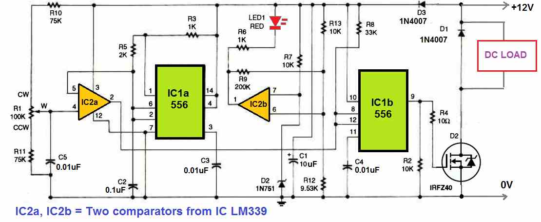
Any DC supply source between 10 and 15 volts can power this DC power controller circuit. A voltage-to-pulse-width converter is created by combining U1a, which is 50 percent of an LM556 dual oscillator/timer and with U2a, which is one-fourth of an LM339 quad comparator, as illustrated in the above circuit diagram.
The dual oscillator/(U1a) timer's first half is set up as an astable oscillator, which produces a ramp voltage that is continually oscillating. Op-amp U2a, which makes up a quarter of the quad comparator, evaluates the voltage at its inverting input and at its non-inverting input, associated with pins 2 and 6 of U1a (pin 4).
Whenever the wiper voltage on R1 is greater than the instantaneous voltage on pins 2 and 6 of U1a, the opamp will provide a low output. The voltage at the wiper of R1 will be approximately equal to the on/off ratio of U2a's output at pin 2.
Because U2a's output cannot handle sufficient power to operate the MOSFET, it is supplied to U1b, which is utilized as a buffer for the signal. The gate of MOSFET Q1 is driven strongly on or off by the low-impedance, pulsed output of U1b at pin 9, resulting in a quick switch on / switch off time.
Additionally, the circuit incorporates a power-input detector constructed around U2b and LED1. LED1 will typically be lighted if the input power is good, but it will turn off if the input voltage falls too low.
If D1 is not included, the MOSFET could be damaged by the reverse voltage spikes produced by inductive loads during switch off periods. D1 can be removed if inductive loads (motors) are not driven by the circuit.
The recommended operating frequency for the number of motors and bulbs that may be used with this circuit would be close to 3500 Hz.
This is the frequency at which the circuit is configured.
There are a few restrictions on this type of switching. This DC power controller circuit should only be used with incandescent light bulbs and permanent-magnet DC motors.
How to Test
The output of the device should be connected to a DC lamp (any 12 volt, 0.5 to 20 watt unit will suffice), and the circuit's input should be connected to an appropriate power source (a vehicle battery would work great).
Once connected the LED should switch on. When the potentiometer is turned all the way to one extreme, the lamp should turn off; when it is turned the opposite extreme, the bulb should gradually get brighter.
That's all, the circuit now complete and in a proper working mode.
Hello.
I have two car batteries 12v which should stay seperated/devided from each other. I want to power my 12v to 5v PSU for arduino from those batteries. I can switch the batteries, so sometimes one or the other or both are switched on. I want my PSU always on, no matter of the switching state of the batteries. Both off – PSU also off. One or the other or both on – PSU on. Can I connect my psu to both batteries connected with two diodes?
Is there a problem if only one would be charged with 30A and the other is on but not charged.
There should be never any current flow between the two batteries? Does a 6A diode also blocks the 30A difference current?
VESPUCCI
Hi, Yes, you can use individual diodes with the battery positives to keep them isolated from each other and allow only the load to be powered through them.
The 30 amp current you are referring to is probably the maximum current delivering capacity of the power supply, and not the consumption of the battery. Meaning the 30 amp current will never be drawn by any of the battery? So the actual current should be much less maybe 3 amp or 6 amp, so a 6 amp diode can be used, especially if its reverse peak voltage is not exceeded.
Yes, you can connect a single power supply to charge both the batteries simultaneously through separate diodes, as shown here:
https://www.homemade-circuits.com/parallel-battery-chargerchangeover/
Thanks a lot!
Is this right?
Load max 3A
______|______
| |
| |
IN5408 IN5408
| |
| |
SLA SLA
Battery Battery
75AH 75AH
| |
| |
Starter Starter
Motor Motor
100A 100A
No problem!…however I cannot interpret your diagram, please show it in a schematic format…
Sry, I did not see, I can insert an image…
May be I should add a fuse? Before or after the diodes?
" rel="ugc">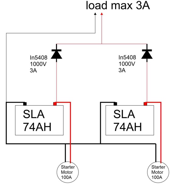
I cannot see the PSU in the diagram. and What are those Starter motor 100A?
the load is my psu. My setup is the following:
it is a catamaran boat with 2 motors.
2x 74Ah lead acid starter batteries to which the starter motors are connected.
sometimes i use only one of the motors.
my dashboard electronics (psu of arduino) needs to be connected to these batteries.
Currently it is connected to the left battery, but if this motor is off, I get no power.
Therefore I am looking for a circuit which allows me to get power weather one or two of the motors are “ignition on”.
VESPUCCI
Thank you for the clarification, however I did not understand the following statement:
“…but if this motor is off, I get no power…”
Can you please elaborate how? Do you mean when the motor is “ON”
Both motors have “ignition switches” which disconnect the battery from the motors and the instruments.
one for the left and one for the right motor/ battery.
that is appreciated. but in case one motor is turned off, the instruments and my “psu for the arduino”
should still be powered. only of both motors are switches off, all instruments should be turned off.
Therefore my idea is to connect my instruments to both battery(switches)to have them always on,
in case one or both motors are on and have them switched off in case both motors are off.
But I don’t want to put the 2 batteries in parallel connection as I don’t want to have current going
from one battery to the other, if they would show different potential.
Thanks for the explanation. In that case, the wiring schematic that you provided in your initial comment looks OK to me. It will make sure, your electronic devices are always ON regardless of any motors being turned OFF.
However if the batteries are connected in parallel that will not harm the batteries, the charge will always equalize between each other.
Thanks a lot for your time! Appreciate!
However if I connect two batteries in parallel with a thin wire and one is empty and the other gets charged with say 30A, don’t I risk to melt the little connection cable as too much Amps want to pass?
Therefore I also asked if the diodes are safe, but in this case the diodes would block the 30A and not let it through, right? So no current flow which could harm, I assume.
Using separate diodes for each battery would be a better idea in that case, as suggested in the following article:
https://www.homemade-circuits.com/parallel-battery-chargerchangeover/