In this article I have explained a step by step tutorial regarding designing your own homemade basic induction heater circuit, which can be also used as an induction cooktop.
Basic Induction Heater Concept
You might have come across many DIY induction heater circuits online but nobody seem to have addressed the crucial secret behind implementing a perfect and a successful induction heater design. Before knowing this secret it would be important to know the basic working concept of an induction heater.
An induction heater is actually an extremely "inefficient" form of electrical transformer, and this inefficiency becomes its main advantageous feature.
We know that in an electrical transformer the core needs to be compatible with the induced frequency, and when there's an incompatibility between frequency and the core material in a transformer, it results in the generation of heat.
Fundamentally an iron cored transformer will require a lower range of frequency around 50 to 100Hz, and as this frequency is increased the core may shown a tendency of getting hotter proportionately. That implies, if the frequency is increased to a much higher level may be over 100kHz would result in the generation of extreme heat within the core.
Yes, this is exactly what happens with an induction heater system where the cooktop acts like the core and therefore is made up of iron material. And the induction coil is subjected to a high frequency, together this results in the generation of a proportionately intense amount of heat on the vessel. Since the frequency is optimized at significantly high level ensures a maximum possible heat on the metal.
Now let's proceed and learn the important aspects that may be required for designing a successful and technically correct Induction heater circuit. The following details have explained this:
What you will Need
The two bare basic things required for building any induction cookware are:
1) A bifilar coil.
2) An adjustable frequency generator circuit
I have already discussed a few induction heater circuits in this website, you can read them below:
Solar Induction Heater Circuit
Induction Heater Circuit Using IGBT
Simple Induction Heater Circuit - Hot Plate Cooker Circuit
Small Induction Heater Circuit for School Project
All the above links have the above two things in common, that is they have a work coil and a driver oscillator stage.
Designing the Work Coil
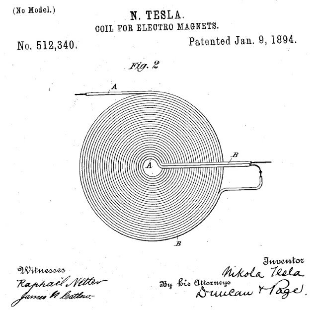
For designing an induction cookware, the work coil is supposed to be flat in nature, therefore it must be bifilar type with its configuration, as shown below:
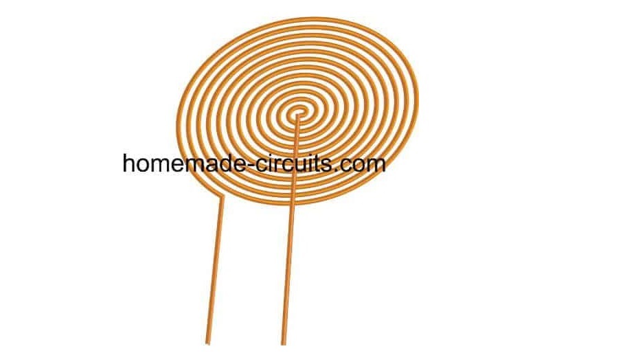
The bifilar coil type design shown above can be effectively implemented for making your homemade induction cookware.
For optimum response and low heat generation within the coil make sure the wire of the bifilar coil is made using many thin strands of copper instead of a single solid wire.
Thus, this becomes the work coil of the cookware, now the ends of this coil simply needs to be integrated with a matching capacitor and a compatible frequency driver network, as shown in the following figure:
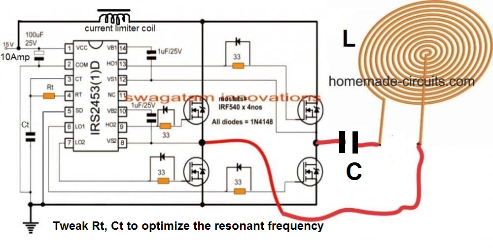
Parts List
- 33 Ohms 1/4 watt 5% = 4 nos
- Rt = To be determined by experimentation.
- 1uF/25V Electrolytic = 2 nos
- 100uF/25V Electrolytic = 1 no
- Ct and C = To be determined by experimentation.
- 1N4148 diodes = 4 nos
- MOSFETs IRF540 = 4 nos
- IC IRS2453 = 1 no
- Work Coil = As shown in the diagram. Diameter will need to be experimented.
- Current limiting Inductor = Can be between 1 mH to 5 mH. Again this one will need to be experimented.
- While experimenting the unknown components make sure to use a 12 V, 50 watt watt bulb in series with the DC supply line, to avoid accidental damage to the MOSFETs.
Designing the H-Bridge Series Resonant Driver Circuit
So far the information should have enlightened you regarding how to configure a simple induction cookware or an induction cooktop design, however the most critical part of the design is how to resonate the coil capacitor network (the tank circuit) into the most optimal range so that the circuit works at the most efficient level.
Enabling the coil/capacitor tank circuit (LC circuit) to operate at their resonance level requires the inductance of the coil and the capacitance of the capacitor to be matched perfectly.
This can happen only when the reactance of both the counterparts are identical, that is the reactance of the coil (inductor) as well as the capacitor are approximately the same.
Once this is fixed you can expect the tank circuit to operate at its natural frequency and the LC network reaching the resonance point. This is called a perfectly tuned LC circuit.
This concludes the basic induction heater circuit designing procedures
You may be wondering regarding what is resonance of an LC circuit.?? And how this may be calculated quickly for completing a specific induction heater design? We will comprehensively discuss this in the following sections.
The above paragraphs explained the fundamental secrets behind developing a low cost yet effective induction cooktop at home, in the following descriptions we will see how this can be implemented by specifically calculating its crucial parameters such the resonance of its tuned LC circuit and the correct dimension of the coil wire for ensuring an optimal current handling capacity.
What is Resonance in Induction Heater LC Circuit
When the capacitor within a tuned LC circuit is momentarily charged, the capacitor tries to discharge and dump the accumulated charge over the coil, the coil accepts the charge and stores the charge in the form of magnetic field. But as soon as the capacitor has discharged in the process, the coil develops an almost equivalent amount of charge in the form of magnetic field and it now tries to force this back inside the capacitor, although with an opposite polarity.
Image courtesy:
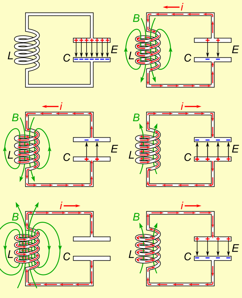
The capacitor is again forced to charge but this time in the opposite direction, and as soon as it's fully charged, it yet again tries to empty itself across the coil, and this results in a back and forth sharing of charge in the form of an oscillating current across the LC network.
The frequency of this oscillating current becomes the resonance frequency of the tuned LC circuit.
However due to inherent losses the above oscillations eventually die out in the course of time, and the frequency, the charge all come to an end after sometime.
But if the frequency is allowed to sustain through an external frequency input, tuned at the same resonance level, then that could ensure a permanent resonance effect being induced across the LC circuit.
At resonance frequency we can expect the amplitude of the voltage oscillating across the LC circuit to be at the maximum level, resulting in the most efficient induction.
Therefore we can imply that, to implement a perfect resonance within an LC network for an induction heater design we need to ensure the following crucial parameters:
1) A tuned LC circuit
2) And a matching frequency to sustain the LC circuit resonance.
This can be calculated using the following simple formula:
F = 1 ÷ 2π x √LC
where L is in Henry and C is in Farad
If you don't want to go through the hassles of calculating the resonance of the coil LC tank through formula, a much simpler option could be to use the following software:
LC Resonant Frequency Calculator
Or you may also build this Grid dip meter for identifying and setting the resonance frequency.
Once the resonance frequency is identified, it's time to set the full-bridge IC with this resonance frequency by suitably selecting the Rt, and Ct timing components. This may be done by some trial and error through practical measurements, or through the following formula:
The following formula can be used for calculating the values of Rt/Ct:
f = 1/1.453 x Rt x Ct where Rt is in Ohms and Ct in Farads.
Using Series Resonance
The induction heater concept discussed in this post uses a series resonant circuit.
When a series resonant LC circuit is employed, we have inductor an (L) and a capacitor (C) connected in series, as shown in the following diagram.
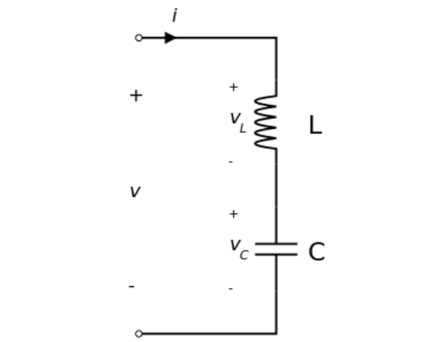
The total voltage V applied across the series LC will be the sum of the voltage across the inductor L and the voltage across the capacitor C. The current flowing through the system will be equal to the current that's flowing through the L and the C components.
V = VL + VC
I = IL = IC
The frequency of the applied voltage affects the reactances of the inductor and the capacitor. As frequency is increased from a minimum value to a higher value, the inductive reactance XL of the inductor will proportionately increase, but XC which is the capacitive reactance will decrease.
However, while the frequency is being increased there will be a particular instance or threshold when the magnitudes of the inductive reactance and the capacitive reactance will be just equal. This instance will be the resonant point of the series LC, and the frequency can be set as the resonant frequency.
Therefore, in a series resonant circuit, the resonance will occur when
XL = XC
or, ωL = 1 / ωC
where ω = angular frequency.
Evaluating the value of ω gives us:
ω = ωo = 1 / √ LC, which is defined as the resonant angular frequency.
Substituting this in the previous equation and also converting the angular frequency (in radians per second) into frequency (Hz), we finally get:
fo = ωo / 2π = 1 / 2π√ LC
fo = 1 / 2π√ LC
Calculating Wire Size for Induction Heater Work Coil
Once you have calculated the optimized values of L and C for the tank circuit of the induction heater and evaluated the exact compatible frequency for the driver circuit, it's time to calculate and fix the current handling capacity of the work coil and the capacitor.
Since the current involved within an induction heater design could be substantially large, this parameter cannot be ignored and must be correctly assigned to the LC circuit.
Using formulas for calculating wire sizes for an Induction wire size may be a little difficult especially for the newcomers, and that's exactly why a special software for the same has been enabled in this site, which any interested hobbyist can use to dimension the right size wire for your induction cooktop circuit.
