In this article I will provide a detailed explanation regarding how to design notch filters with precise center frequency and for maximum impact.
Where Notch Filter are Used
Notch filter circuits are normally used for suppressing, nullifying, or cancelling a particular range of frequencies in order to avoid an annoying or unwanted interference within a circuit configuration.
It specifically becomes useful in sensitive audio equipment such as amplifiers, radio receivers where a single or a selected number of unwanted interfering frequencies are required to be eliminated through a simple means.
Active notch filters were actively used during the earlier decades for amplifier and audio applications for eliminating of 50- and 60-Hz hum interferences. These networks have been although somewhat awkward from the standpoints of center notch frequency (f0) tuning, balance, and consistency.
With the introduction of the modern high speed amplifiers, it became imperative to create compatible high speed notch filters which could be applied for handling high speed notch frequency filtration at an efficient rate.
Here we'll try to investigate the possibilities and the associated complexities involved with the making of high notch filters.
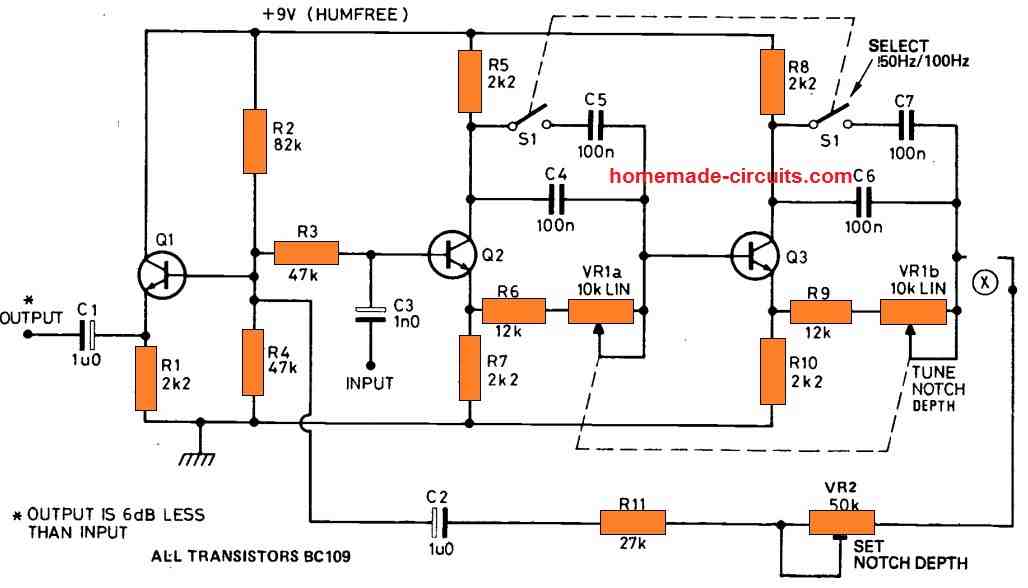
Adjustable 50 Hz Notch Filter Application Circuit
Magnetically generated hum interference has a frequency of 50Hz, whereas ripple induced hum has a frequency of 100Hz. This circuit can handle both kind with the help of a switch that allows either 50Hz or 100Hz functioning. The filter is made up of a couple of transistor stages, each of which delays the signal by 90°. At point X, the maximum delay across Q2 and Q3 thus is 180°.

Important Characteristics
Before delving into the subject let's first summarize the important characteristics that may be strictly required while designing the proposed high speed notch filters.
1) The steepness of the null depth that's indicated in the figure1 simulation may not be feasible practically, the most efficient achievable results could be not above 40 or 50dB.
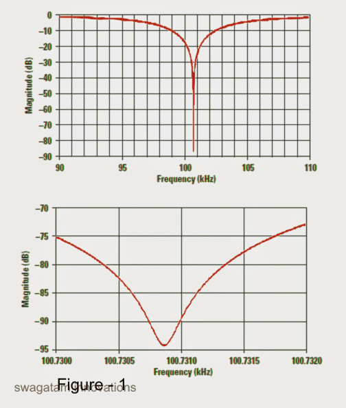
2) Therefore, it must be understood that the more significant factor to be improved is the center frequency and the Q, and the designer should focus on this instead of the depth of the notch. The main objective while making a notch filter design should be the level of rejection of the unwanted interfering frequency, this must be optimal.
3) The above issue can be resolved optimally be preferring the best values for the R and the C components, which can be implemented by correctly using the RC calculator shown in Reference 1, which can be used for appropriately identifying the R0, and C0 for a particular notch filter designing application.
The following data will explore and help to understand the designing of some interetsing notch filter topologies:
Twin-T Notch Filter
The Twin-T filter configuration shown in the figure3 looks quite interesting due to its good performance and the involvement of just a single opamp in the design.
Schematic
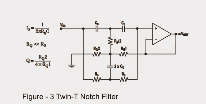
Although the above indicated notch filter circuit is reasonably efficient, it might have certain disadvantageous owing to the extreme simplicity that it bears, as given below:
The design makes use of 6 precision components for its tuning, wherein a couple of these for attaining ratios of the others. If this complication requires to be avoided, the circuit might require the inclusion of 8 additional precision components, such as R0/2 = 2nos of R0 in parallel and 2 into C0 = 2 nos of C0 in parallel.
A Twin-T topology doesn't readily work with single power supplies, and does not comply with full-fledged differential amplifiers.
The range of resistor values keeps increasing due to the RQ < < R0 necessity which in turn may influence on the level of depth of the desired center frequency.
However, even with the above hassles, if the user succeeds in optimizing the design with high quality precise components, a reasonably effective filtration can be expected and implemented for the given application.
The Fliege Notch Filter
Figure4 indicates the Fliege Notch filter design, which identifies a few distinct advantages when compared with the Twin-T counterpart, as narrated below:
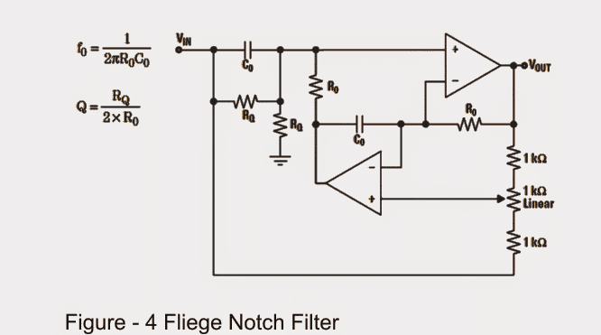
1) It incorporates just a couple of precision components in the form of Rs and Cs in order to fulfill an accurate center frequency tuning.
2) One appreciable aspect about this design is that it allows slight inaccuracies within the components and the settings without affecting the depth of the notch point, although the center frequency could change a bit accordingly.
3) You'll find a couple of resistors responsible for determining the center frequency discretely whose values may not be extremely critical
4) The configuration enables the setting up of the center frequency with a reasonably narrow range without influencing the notch depth to a significant level.
However, the negative thing about this toplogy is its use of two opamps, and yet still it does not become usable with differential amplifiers.
Simulations Results
Simulations were initially accomplished with most suitable opamp versions. True-to-life opamp versions were soon after employed, which generated outcomes comparable to those detected in the lab.
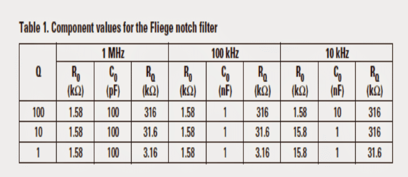
Table 1 demonstrates the component values which were put to use for the schematic in Figure 4. There seemed to be no sense in carrying out simulations at or above 10 MHz mainly because laboratory tests were essentially conducted as a start-up, and 1 MHz was the leading frequency where a notch filter was needed to be applied.
A word regarding capacitors: Despite the fact that the capacitance is merely a "number" for simulations, real capacitors are designed of unique dielectric elements.
For 10 kHz, resistor value stretch obligated the capacitor to a value of 10 nF. Although this did the trick correctly in demo, it called for an adjustment from an NPO dielectric to an X7R dielectric in the lab which caused the notch filter to utterly drop with its feature.
Specifications of the 10-nF capacitors applied were in close proximity in value, as a result the decline in notch depth was mainly liable on account of poor dielectric. The circuit was forced to revert to the respects for a Q = 10, and a 3-MΩ for R0 was employed.
For real-world circuits, it is advisable to abide by NPO capacitors. The requirement values in Table 1 were considered a good choice equally in simulations and in lab development.
At the beginning, the simulations were performed without the 1-kΩ potentiometer (the two 1-kΩ fixed resistors were associated specifically in sync, and to the non inverting input of the lower opamp).
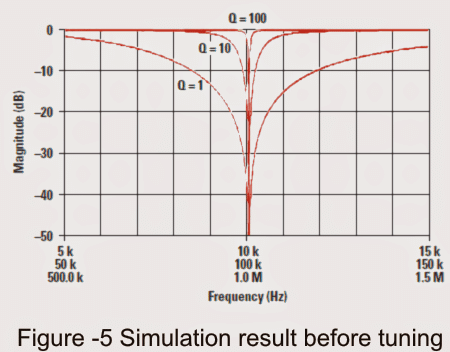
Demo outputs are presented in Figure 5. You will find 9 pieces of results in Figure 5, however you may find the waveforms per Q value overlap those at the other frequencies.
Calculating Center Frequency
The center frequency in any circumstance is moderately above a structure objective of 10 kHz, 100 kHz, or 1 MHz. This can be as near as a developer can acquire with an accepted E96 resistor and E12 capacitor.
Think about the situation using a 100 kHz notch:
f = 1 / 2πR0C0 = 1 / 2π x 1.58k x 1nF = 100.731 kHz
AS can e seen, the result looks slightly of the mark, this can be further streamlined and made closer to the required value if the 1nF capacitor is modified with a standard E24 value capacitor, as demonstrated below:
f = 1 / 2π
x 4.42k x 360 pF = 100.022 kHz, looks much better
The use of E24 version capacitors can bring about substantially more precise center frequencies most of the time, yet somehow obtaining the E24 series quantities might be a high-priced (and an undue) overheads in numerous labs.
Although it could be convenient to evaluate E24 capacitor values in hypothesis, in real world the majority of them are hardly ever implemented, as well as have extended run times involved with them. You will discover less complicated preferences to buying E24 capacitor values.
Thorough evaluation of Figure 5 determines that the notch misses the center frequency by a modest amount. At lesser Q values, you can find still considerable cancellation of the specified notch frequency.
In case the rejection is not satisfactory, then you may want to tweak the notch filter.
Back again, contemplating the scenario of 100 kHz, we observe that the reaction around 100 kHz is extended in Figure6.
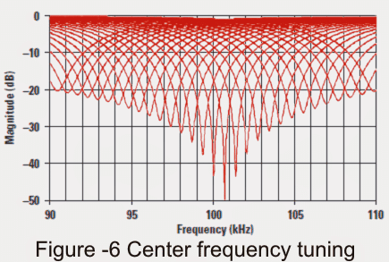
The collection of waveforms to the left and right of the center frequency (100.731 kHz) corresponds to filter reactions, once the 1-kΩ potentiometer is positioned and tweaked in 1% increments.
Every time the potentiometer is tuned halfway, the notch filter rejects frequencies at the precise core frequency.
The degree of the simulated notch is in fact on the order of 95 dB, however this is simply not supposed to materialize in the physical entity.
A 1% realignment of the potentiometer places a notch which is usually exceeding 40 dB straight on the preferred frequency.
Once again, this really may be the best scenario when done with ideal components, nevertheless lab data show more accurate at lower frequencies (10 and 100 kHz).
Figure 6 determines that you need to achieve a much closer to the precise frequency with R0 and C0 at the very start. As the potentiometer may be able to rectify frequencies over an extensive spectrum, the depth of the notch could degrade.
Over a modest range (±1%), one may achieve a 100:1 rejection of the bad frequency; nevertheless over an increased range (±10%), only a 10:1 rejection is feasible.
Lab results
A THS4032 evaluation board was implemented to put together the circuit in Figure 4.
It is actually a general-purpose structure using merely 3 jumpers along with traceto finalize the circuit.
The component quantities in Table 1 were applied, beginning with those that would probably churn out a 1 MHz frequency.
The motive was to hunt for bandwidth/slew-rate regulations at 1 MHz and check at more affordable or higher frequencies as needed.
Results at 1 MHz
Figure 7 signifies that you can get a number of specific bandwidth and/or slew-rate reactions at 1 MHz. The reaction waveform at a Q of 100 exhibits just a ripple wherein the notch may be present.
At a Q of 10, there exists just a 10-dB notch, and a 30-dB notch at a Q of 1.
It seems that notch filters are unable to accomplish as high a frequency as we would likely anticipate, nevertheless the THS4032 is simply a 100-MHz device.
It is natural to anticipate superior functionality from components with an improved unity-gain bandwidth. Unity-gain stability is critical, for the reason that the Fliege topology carries fixed unity gain.
When the creator hopes to approximate precisely what bandwidth is essential to a notch at a specific frequency, a right place to go about is the gain/bandwidth combination as presented in the datasheet, that should be one hundred times the center frequency of the notch.
Supplementary bandwidth might possibly be expected for increased Q values. You can find a degree of frequency deviation of the notch center as Q is modified.
This is exactly same as the frequency transition noticed for bandpass filters.
The frequency transition is lower for notch filters applied to work at 100 kHz and 10 kHz, as laid out in Figure 8 and eventually in Figure 10.
Data at 100 kHz
Part quantities from Table 1 were subsequently accustomed to establish 100-kHz notch filters with diverse Qs.
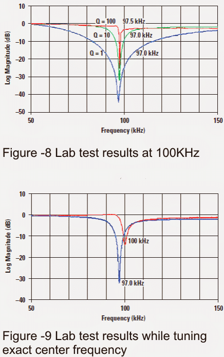
The data are presented in Figure 8. It looks straightaway crystal clear that workable notch filters are typically developed with a center frequency of 100 kHz, despite the fact that the notch depth happens to be significantly less at bigger values of Q.
Keep in mind, however, that the configuration objective listed here is a 100-kHz not a 97-kHz-notch.
The part values preferred were the just the same as for the simulation, hence the notch center frequency needs to be technically at 100.731 kHz; nevertheless the impact is spelled out by the components included in the lab design.
The average value of the 1000-pF capacitor assortment was 1030 pF, and of the 1.58-kΩ resistor assortment was 1.583 kΩ.
Any time the center frequency is worked out using these values, it arrives to 97.14 kHz. The specific parts, in spite of this, could hardly be determined (the board was extremely sensitive).
Provided that the capacitors are equivalent, may well be easy to get higher through some conventional E96 resistor values to achieve results tighter to 100 kHz.
Needless to say, this could be most likely not an alternative in high-volume production, where 10% capacitors could possibly originate from virtually any package and probably from diverse manufacturers.
The selection of center frequencies is going to be according to the tolerances of R0 and C0, which is bad news in case a high Q notch becomes necessary.
There are 3 methods of coping with this:
Buy higher-precision resistors and capacitors;
minimize the Q specification and settle for lesser rejection of the undesired frequency; or
fine-tune the circuit (that had been contemplated subsequently).
Right now, the circuit appears to be personalized to receive a Q of 10, and a 1-kΩ potentiometer integrated for tuning the center frequency (as revealed in Figure 4).
In real-world layout, the potentiometer value preferred ought to be a little more than the required range to cover the full range of center frequencies as much as possible even with worst case of R0 and C0 tolerances.
That had been not accomplished at this point, because this was an example in analyzing potentialities, and 1 kΩ was the most competitive potentiometer quality accessible in the lab.
When the circuit was adjusted and tuned for a center frequency of 100 kHz as outlined in Figure 9, the notch level degraded from 32 dB to 14 dB.
Keep in mind that this notch deepness could possibly be dramatically enhanced by providing the preliminary f0 tighter to the best suitable value.
The potentiometer is intended to be tweaked over exclusively a modest area of center frequencies.
However, a 5:1 rejection of an undesired frequency is creditable and could very well be adequate for many utilization. Far more crucial programs can undeniably call for higher-precision parts.
Op amp bandwidth restrictions, that has the capability to additionally degrade the tuned notch magnitude, may also be responsible of stopping the notch degree from getting as small as feasible. Bearing this in mind, the circuit was again adjusted for a center frequency of 10 kHz.
Results at 10 kHz
Figure 10 determines that the notch valley for a Q of 10 has augmented to 32 dB, that could be by what you can anticipate from a center frequency 4% off from the simulation (Figure 6).
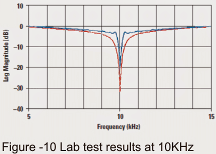
The opamp was without a doubt reducing the notch deepness at a center frequency of 100 kHz! A 32-dB notch is a cancellation of 40:1, that could be reasonably decent.
Therefore in spite of parts that engineered a preliminary 4% error, it had been easy to churn out a 32-dB notch at the most wanted center frequency.
The unpleasant news is the fact that to evade opamp bandwidth constraints, the highest possible notch frequency conceivable with a 100-MHz opamp is approximately 10 and 100 kHz.
When it comes to notch filters, “high-speed” is accordingly considered genuine at around hundreds of kilohertz.
A superb practical application for 10-kHz notch filters is AM (medium-wave) receivers, in which the carrier from neighboring stations generates a loud 10-kHz screech in the audio, specifically during the night. This could certainly grate on one’s nerves while tuning in is continuous.
Figure 11 displays the picked up audio spectrum of a station without using and using the 10-kHz notch was implemented. Notice that the 10-kHz noise is the most loud section of the picked up audio (Figure 11a), even though the human ear is substantially less susceptible to it.
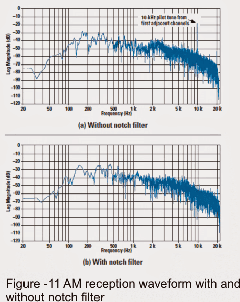
This audio range was captured at nighttime on a nearby station that received a couple of powerful stations on both side. FCC stipulations permit certain variance of the station carriers.
For that reason, modest pitfalls in carrier frequency of the two neighboring stations is likely to make the 10-kHz noises heterodyne, boosting the annoying listening experience.
Whenever the notch filter is implemented (Figure 11b), the 10-kHz tone is minimized to the matching level as that of the adjacent modulation. Furthermore observable on the audio spectrum are 20-kHz carriers from stations 2 channels away and a 16-kHz tone from a transatlantic station.
These are generally not a big concern, since they are attenuated considerably by the receiver IF. A frequency at around 20 kHz may be inaudible to the overwhelming majority of individuals in either case.
References:
http://www.ti.com/lit/an/snoa680/snoa680.pdfhttp://www.ti.com/lit/an/sbfa012/sbfa012.pdf
http://www.ti.com/lit/an/slyt235/slyt235.pdf
https://en.wikipedia.org/wiki/Band-stop_filter
Hello,
Is this the best circuit to use in a high quality audio system? 9db notch @ 5.2Khz I have opamp input and output buffers and with a fixed frequency I use a dual potentiometer to control the Q, 1–10
Your thoughts
Thanks
Yes, the first circuit looks good, however there are even better designs which you can find, under the following posts.
https://www.homemade-circuits.com/simple-hum-filter-circuit-for-amplifiers/
https://www.homemade-circuits.com/active-filter-circuits-using-op-amps/
https://www.homemade-circuits.com/design-high-pass-filter-circuit-quickly/
At the center of your essence you have the answers; you understand your power and you know what you needed.