The diac is a two-terminal device having a combination of parallel-inverse semiconductor layers, which allows the device to be triggered through both directions regardless of the supply polarity.


Diac Characteristics
The characteristics of a typical diac can be seen in the following Figure, which distinctly reveals the presence of a breakover voltage in across both of its terminals.
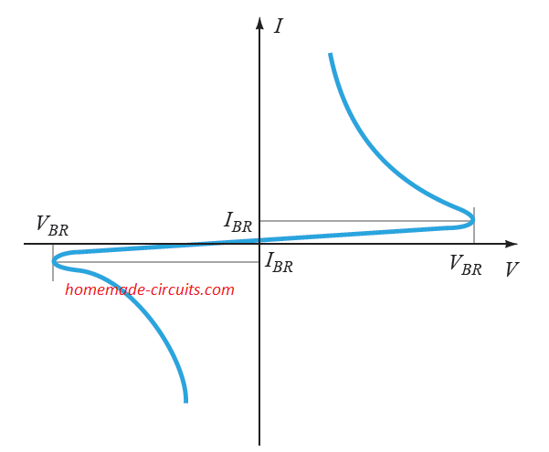
Since a diac can be switched in both directions or bidirectionally, the feature is effectively exploited in many AC switching circuits.
The next figure below illustrates how the layers are arranged internally, and also shows the graphical symbol of the diac. It may be interesting to note that both the terminals of the diac are assigned as anodes (anode 1 or electrode 1 and an anode 2 or electrode 2) , and there is no cathode for this device.
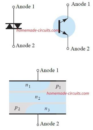
When the connected supply across the diac is positive on anode 1 with respect to anode 2, the relevant layers function as p1n2p2 and n3.
When the connected supply is positive on anode 2 with respect to anode 1, the functional layers are as p2n2p1 and n1.
Diac Firing Voltage Level
The breakdown voltage or the firing voltage of diac as indicated in the first diagram above, seems to be quite uniform across both terminals. However, in an actual device this could vary anywhere from 28 V to 42 V.
The firing value could be achieved by solving the following terms of the equation as available from the datasheet.
VBR1 = VBR2 ± 0.1VBR2
The current specifications (IBR1 and IBR2) across the two terminals also appears to be quite identical. For the diac which is represented in the diagram
The two current levels (IBR1 and IBR2) for a diac are also very close in magnitude. In the example characteristics above, these appear to be around
200 uA or 0.2 mA.
Diac Applications Circuits
The following explanation shows us how a diac works in an AC circuit. We will try to understand this from a simple 110 V AC operated proximity sensor circuit.
Proximity Detector Circuit
The proximity detector circuit using a diac can be witnessed in the following diagram.
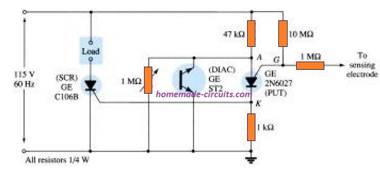
Here we can see that an SCR is incorporated in series with the load and the programmable unijunction transistor (PUT) which is joined with the sensing probe directly.
When a human body comes near to the sensing probe, causes an increase in the capacitance across the probe and the ground.
As per the characteristics of a silicon programmable UJT, it will fire when the voltage VA at its anode terminal exceeds its gate voltage by at least 0.7 V. This causes a short circuit across the anode cathode of the device.
Depending on the setting of the 1M preset, the diac follows the input AC cycle and fires at a specified voltage level.
Due to this continues firing of the diac, the anode voltage VA of the UJT is never allowed to increase its gate potential VG which is always held at almost as high as the input AC. And this situation keeps the programmable UJT switched OFF.
However, when a human body approaches the sensing probe, it lowers the gate potential VG of the UJT substantially, allowing the anode potential VA of the UJT of the UJT to go higher than VG. This instantly causes the UJT to fire.
When this happens, the UJTs creates a short across its anode/cathode terminals, providing the necessary gate current for the SCR. The SCR fires and switches ON the attached load, indicating the presence of a human proximity near the sensor probe.
Automatic Night Lamp
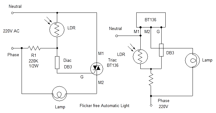
A simple automatic mast light circuit using an LDR, triac and a Diac can be see in the above drawing. The working of this circuit is pretty simple, and the critical switching job is handled by the diac DB-3. When evening sets in, the light on the LDR starts falling, which causes the voltage at the junction of R1, DB-3 to gradually rise, due to the increasing resistance of the LDR.
When this voltage rises to the break over point of the diac, the diac fires and actuates the triac gate, which in turn switches ON the connected lamp.
During morning, the light on the LDR gradually increases, which causes the potential across the diac to diminish due to grounding of the R1/DB-3 junction potential. And when the light is sufficiently bright, the LDR resistance causes the diac potential to drop to almost zero, switching off the triac gate current, and hence the lamp is also switched OFF.
The diac here ensures that the triac is switched without much flickering during the twilight transition. Without the diac, the lamp would have flickered for many minutes before switching completely ON or OFF. Thus the breakdown triggering feature of the diac is thoroughly exploited in favor of the automatic light design.
Light Dimmer
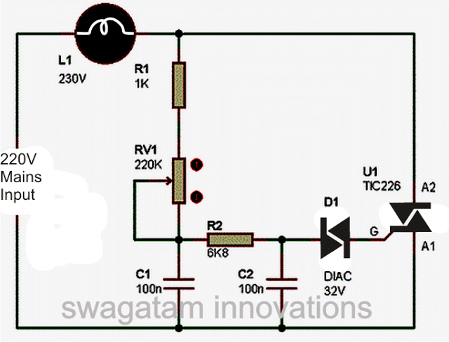
A light dimmer circuit is perhaps the most popular application using a triac diac combination.
For each cycle of the AC input the diac fires only when the potential across it reaches its breakdown voltage. The time delay after which the diac fires decides for how much time the triac remains switched ON during each cycle of the phase. This in turn decides the amount of current and illumination on the lamp.
The time delay in firing the diac is set by the shown 220 k pot adjustment, and the C1 value. This RC time delay components determine the ON time of the triac through the diac firing which results in chopping of the AC phase over specific sections of the phase depending on the firing delay of the diac.
When the delay is longer, a narrower portion of the phase is allowed to switch the triac and trigger the lamp, causing lower brightness on the lamp. For quicker time intervals, the triac is allowed to switch for longer periods of the AC phase, and thus the lamp also is switched for longer sections of the AC phase causing higher brightness on it.
Amplitude Triggered Switch
The most basic application of the diac without depending on any other part, is through automatic switching. For an ac or dc supply the diac behaves like a high resistance (practically an open circuit) so long as the applied voltage is below the critical VBO value.
The diac switches ON as soon as this critical VBO voltage level is achieved or surpassed. Therefore, this specific 2-terminal device could be turned on just by increasing the amplitude of the attached control voltage, and it could go on conducting, until eventually the voltage is decreased to zero. Figure below displays a straightforward amplitude-sensitive switch circuit by using a 1N5411 diac or a DB-3 diac.
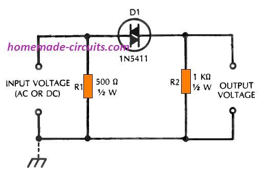
An voltage of around 35 volts dc or peak ac is applied which switches ON the diac into conduction, due to which a current of around 14 mA begins flowing through the output resistor, R2. Specific diacs may possibly turn on at voltages below 35 volts.
Using 14 mA switching current, the output voltage created across the 1k resistor gets to 14 volts. In case the supply source includes an inside conductive path within the output circuit, resistor R1 could be ignored and eliminated.
While working with the circuit, try adjusting the supply voltage so that it gradually increases from zero while simultaneously check the output response. When the supply reaches around 30 volts, you will see small or slight bit of output voltage, due to the extremely low leakage current from the device.
However, at roughly 35 volts, you will find the diac suddenly breaking down and a full output voltage quickly showing up across resistor R2. Now, start reducing the supply input, and observe that the output voltage correspondingly reduces, finally getting at zero when the input voltage is reduced to zero.
At zero volts, the diac is completely "shut off," and goes into a situation which requires it to be triggered again through the 35 volt amplitude level.
Electronic DC Switch
The simple switch detailed in the previous section could be likewise activated through an small increase in the supply voltage. Therefore, a stable voltage of may be 30 V could be employed consistently to the 1N5411 diac ensuring that the diac is just at the vege of conduction but still switched OFF.
However the moment a potential of approximately 5 volts is added in series, the breakdown voltage of 35 volts is quickly achieved to execute the firing of the diac.
Removing this 5 volt "signal" subsequently has no impact on the turned ON situation of the device, and it continues to remain conducting the 30 volt supply until the voltage is lowered to zero volts.
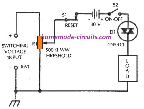
Figure above demonstrates a switching circuit featuring the theory of incremental voltage switching as explained above. Within this set up, a 30 volt is supply is given to the 1N5411 diac (D1) (here this supply is shown as a battery source for convenience, nevertheless the 30 volts could be applied through any other constant regulated source dc). With this voltage level, the diac is unable to turn ON, and no current runs via the connected external load.
However, when the potentimeter is gradually adjusted, the supply voltage slowly increases and finally the diac is turned ON, which enables the current to pass through the load and switch it ON.
Once the diac is switched ON, decreasing the supply voltage through the potentiometer has no effect on the diac. However, after reducing the voltage through the potentiometer, the reset switch S1 could be used for toggling OFF the diac conduction and reset the circuit in the original switched Off condition.
The shown diac or DB-3 will be able to remain idle at around 30 V, and will not go through a self firing action. That said, some diacs may require lower voltages than 30 V to keep them in the non-conducing condition. In the same way specific diacs may require higher than 5 V for the incremental switch ON option. The value of the potentiometer R1 should not be more than 1 k Ohms,, and should be wire wound type.
The above concept can be used for implementing latching action in low current applications through a simple two terminal diac device instead of depending on complex 3 terminal devices like SCRs.
Electrically Latched Relay
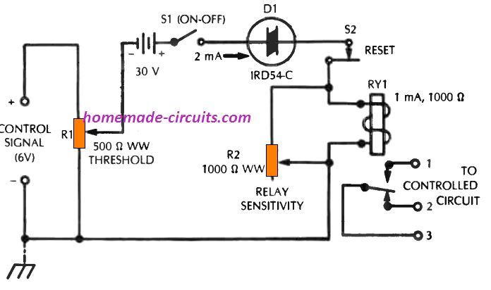
Figure shown above indicates the circuit of a dc relay which is designed to remain latched the moment it is powered through an input signal. The design is as good as latching mechanical relay.
This circuit makes use of the concept explained in the previous paragraph. Here also, the diac is held switched off at 30 volts, a voltage level that's typically small for a diac conduction.
However, as soon as a 6 V series potential is given to the diac, the latter begins pushing current which switches ON and latches the relay (the diac after that remains switched ON, even though the 6 volt control voltage no longer exists).
With R1 and R2 optimized correctly, the relay will switch ON efficiently in response to an applied control voltage.
After this the relay will remain latched even without the input voltage. However, the circuit can be reset back to its previous position by pressing the indicated reset switch.
The relay has to be a low current type, may be with a coil resistance of 1 k.
Latching Sensor Circuit
Many devices, for example intruder alarms and process controllers, demand a triggering signal that stays switched ON once triggered and switches OFF only when power input is reset.
As soon as the circuit is initiated, it enables you to operate circuitry for alarms, recorders, shutoff valves, safety gadgets, and many others. Figure below exhibits an example design for this type of application.
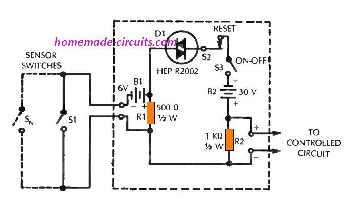
Here, a HEP R2002 diac works like a switching device. In this particular set up, the diac stays in the stand-by mode at 30 volts supply through B2.
But, the moment switch S1 is toggled, that could be a "sensor" on a door or window, contributes 6 volts (from B1), to the existing 30 V bias, causing the resultant 35 volts to fire the diac and generate around 1 V output across R2.
DC Overload Circuit Breaker
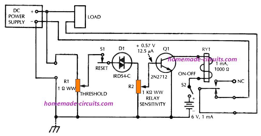
Figure above demonstrates a circuit that will instantly switch off a load when the dc supply voltage surpasses a fixed level. The unit then stays turned off until the voltage is lowered and the circuit is reset.
In this particular set up, the diac (D1) is normally switched OFF, and transistor current is not high enough to trigger the relay (RY1).
When the supply input goes beyond a specified level as set by the potentiometer R1, the diac fires, and the DC from the diac output reaches the transistor base.
The transistor now switches ON through potentiometer R2 and activates the relay.
The relay now disconnects the load from the input supply, preventing any damage to the system due to overload. The diac after that continues to be switched ON keeping the relay turned ON until the circuit is reset switch, by opening the S1, momentarily.
In order to adjust the circuit in the beginning, fine-tune potentiometers R1 and R2 to ensure that the relay just clicks ON once the input voltage actually reaches the desired diac firing threshold.
The relay after that must keep activated until the voltage reduces back to its normal level and the reset switch is momentarily opened.
If the circuit works properly, the diac "firing" voltage input must be around 35 volts (specific diacs could activate with a smaller voltage, although this is often corrected by adjusting of potentiometer R2), as well as the dc voltage at the transistor base must be roughly 0.57 volt (at around 12.5 mA). The relay is a 1k coil resistance.
Ac Overload Circuit Breaker
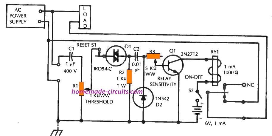
The circuit diagram above demonstrates the circuit of an ac overload circuit breaker. This idea works the identical way as the dc set up explained in the earlier {part. The ac circuit {differs|varies} from the dc version due to the presence of the capacitors C1 and C2 and diode rectifier D2.
Phase Controlled Triggering Switch
As stated before, the primary use of the diac is to source an activation voltage to some device such as a triac for controlling a desired equipment. The diac circuit in the following implementation is a phase control process which can find many applications other than triac control, in which a variable phase pulse output may be necessary.
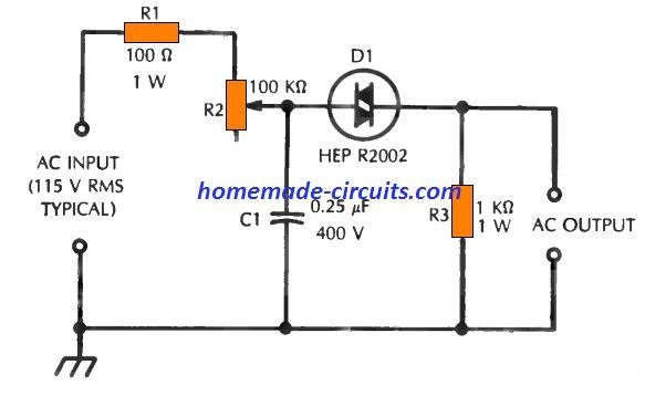
Figure above displays typical diac trigger circuit. This set up fundamentally regulates the firing angle of the diac, and this is achieved by manipulating the phase control network built around the parts R1 R2 and C1.
The values of the resistance and capacitance provided here are as reference values only. For a specific frequency (generally the AC mains line frequency), R2 is tweaked in order that the diac break-over voltage is attained at an instant that corresponds to the preferred point in the ac half cycle where the diac is required to switch on and provide the output pulse.
The diac following this may keep repeating this activity throughout each +/- AC half cycle. Eventually, the phase is decided not just by R1 R2 and C1, but also through the impedance of the ac source and the impedance of the circuit which the diac set up activates.
For the majority of applications, this diac circuit project will likely be beneficial to analyze the phase of the diac resistance and capacitance, to know efficiency of the circuit.
The following Table below, for instance, illustrates the phase angles which may correspond to different settings of the resistance in accordance with the 0.25 µF capacitance in the figure above.

The information are shown intended for 60 Hz. Remember, as indicated in the table as the resistance is decreased, the trigger pulse keeps appearing in earlier positions in the supply voltage cycle, which causes the diac to "fire" earlier in the cycle and to remain switched ON that much longer. Since the RC circuit includes series resistance and shunt capacitance, the phase is, naturally, lagging that signifies that the trigger pulse comes after the supply voltage cycle within time cycle.
Hi dear friend
Please enable the centrifugal switch circuit diagram for a single-phase electric motor using electronic elements. I also used your excellent educational materials
Thank/
Email:
gh.birgani@gmail.com
Thank you Friend, Presently I do not have the design with me, but I will surely try to update a new article on centrifugal switch controlled motor, soon.