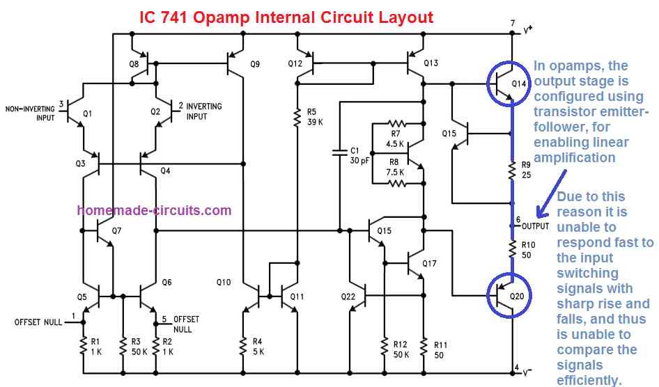
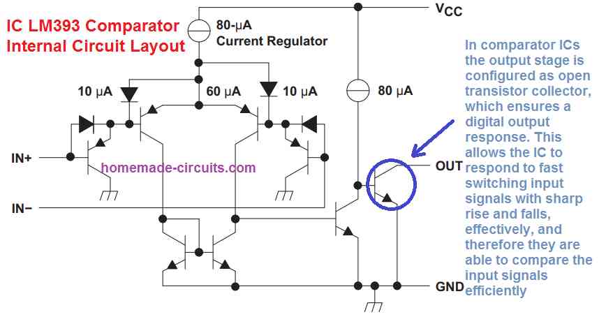
In this article I have explained the main differences between op amp and comparator, and try to understand why op amps are not ideally suited to be used like compartaors. We also learn the main advantages of using compartaor ICs in comparator applications.
Basically, you will find many electronic lectures or publications talking about using an operational amplifier like a comparator. In this article we take a look on this subject in greater depth, and find out exactly how the idea may usually be a bad idea.
The concept used in designing the comparator is straightforward.
Using Op amp like Comparator
An op amp includes an extremely high open-loop DC gain, meaning that even a small amount of differential input voltage could push the output to one extreme of the supply voltage or to the other extreme.
When the voltage applied at the non-inverting (‘+’) input of an op amp is higher than the voltage at the inverting (‘-’) input, then the output switches to high (equal to the positive supply level); and in the opposite case the op amp output turns low (equal to zero volts).
To put it differently, a couple of voltage levels are compared across the input pins, causing the output to generate a binary signal indicating which input pin voltage is greater, and which input is lower.
In the above example, the op amp appears like the ideal device to be used like a comparator. Yet, why do we then have specialized comparator devices available?
Externally Opamps and Comparator ICs Look Similar


Seen externally, opamps and comparators appear to have no difference at all.
Both device have identical power supply connections, both include ‘+’ and ‘-’ input pinouts and a solitary output pin.
Examining the inner circuit configuration, we find that once again both units look largely the same (although a comparator IC having an open-collector or open-drain output might appear much different to an op amp).
Differences Between Op amps and Comparator ICs
1) Op Amp output works in linear mode, Comparator output works in saturation mode
The significant difference, that is not noticeable until the circuit is examined more carefully, is the op amp output stages which are created for linear functioning, with the basic purpose of amplifying the input signal with as minimum distortion as possible (by introducing little bit of negative feedback).


However when it comes to a comparator the internal output circuit is built to work in saturation mode, meaning, to ensure switching between the upper and lower supply limits of output voltage without depending on an external feedback.
Comparators usually also come with a ground connection besides the normal power supply connections, and deliver digital logic levels on their outputs, although it can also accept symmetrical analogue input signals.
What do these differences actually indicate in practical use?
Comparators have Faster Response time than Op Amps
Comparators are able to respond rapidly to voltage variations on their input pins using small propagation delays and output rise-and fall-times, as specified by the manufacturer. In comparison, since op amps are generally not supposed to be applied in the above function, manufacturers usually do not provide precise technical specs for propagation delay and rise-and fall times (although the slew rate is generally provided).
All these specifications are usually significantly inferior in opamps compared to comparators.
Considering a serious illustration, a low-power op amp could possess a propagation delay tested in milliseconds, while a comparator may well respond in nanoseconds: which is a million times quicker.
There exists an additional issue with op amps.
Op Amps may Consume High Power in Saturation mode, Comparators don't
Many opamp unit display an increased power consumption during saturated output. The generated power dissipation due to high power consumption can be enough to damage the opamp.
Furthermore, many of the op amps are generally not competent at switching their outputs near to the supply voltage levels. For example it may produce a highest possible output voltage of 3 V when a 5 V supply is used.
You may also find their inputs having restricted operating limits. A few op amps include anti-parallel diodes on their input terminals, in order to stop differential input voltages higher than approximately 0.6 V in contrast to comparators inputs which are usually permitted to vary within the entire supply range.
Undoubtedly , you will find numerous less critical applications in which an op amp may perform flawlessly just like a comparator, but still it may not be recommended to use an opamp instead of a comparator.
Test Results
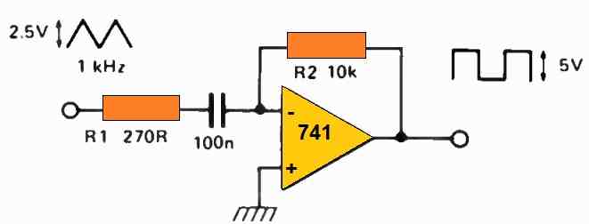
Folks who don't want to accept these differences can have a quick test of a comparator and an op amp simultaneously. The testing may be done by supplying each device with a squarewave signal having sharp and fast edges.
Several prospective downfalls could be proven quickly through simulation, for example the probability of an op amp performing at such slow speeds that it simply misses out the narrow pulses.
Op Amps are Less Efficient than Comparators
Using op amp it may not be possible to guarantee circuit efficiency, current consumption, and even whether the device will get damaged or not.
Tests prove that the comparator reacts faster using a lot smaller rise-time. Its output voltage switching can be right up to +5 V instead of 3 V normally seen in an op amp output. The same function can be witnessed when the output turns low, and the comparator output can reach a minimum of -5 V. In such situations the op amp responds very slowly and is able to reach an output voltage of just -3 V instead of the intended -5 V.
In op amps, the original input squarewave is barely the same as the output squarewave. An op amp may completely be unsuccessful to handle shorter pulses, which usually tend to die out entirely, while the comparator effectively takes care of them quite easily.
Summarizing the Main Differences Between Op amp and Compartaor
- Op amps are designed to work efficiently in the linear mode, whereas comparators are designed to work efficiently in the saturation mode.
- The main function of op amps is to amplify an analogue input signal. The main function of comparators is to compare two varying input signals and produce corresponding binary outputs, switching between the supply levels.
- Comparators are significantly faster than op amps when it comes to comparing and responding to varying voltage levels at their input pins.
- While comparing fast square waves at their inputs, an op amp can miss out and ignore narrow pulses, whereas comparators will never miss even the narrowest of the pulses.
- While comparing inputs signals, an op amp output may not switch up to the supply level extremes, but in comparators, the output switching will efficiently reach the extreme levels of the DC supply.
- An op amp when saturated may tend to heat up and burn, but a comparator will run smoothly in the saturated mode.
- Offset output voltage in op amps is significantly high, whereas in comparators the offset voltage is negligibly low.

Have Questions? Please Leave a Comment. I have answered over 50,000. Kindly ensure the comments are related to the above topic.
Sir…plz provide me a differentiator + comparator circuit ,that detects the positive slope of a decreasing signal and lights up an LED when positive slope is detected. I’ll be feeding the custom voltage signal from the Arduino UNO board.
Hi Joe,
Here’s a differentiator circuit:
And for the comparator circuit you can refer to the following article:
https://www.homemade-circuits.com/how-to-use-ic-741-as-comparator/
But sorry, i have no idea how to combine them to fulfill your requirement…??
Thanks, great answer yours is a much much better than what ChatGPT suggested.
Thanks and Glad you found the post useful.