In this article we'll study a digital stopwatch design configured around the very popular IC LM555 in conjunction with a 4-digit counter IC with multiplexed 7-segment output drivers (MM74C926).
Written and Submitted by: Jennifer Goldy
Circuit Operation
IC MM74C926 is internally made up of a 4-digit counter, an output latch up stage, a npn output responsible for sourcing driver networks for common-cathode, 7-segment display and an internal multiplexing circuitry with four multiplexing outputs.
The multiplexing circuit stage also includes an in-built free running oscillator, and does not rely on any additional external frequency generating network.
The counter is designed to proceed on a negative rising of the clock signals.
The clock signal is manufactured by the timer IC LM555 (IC1) and impressed over pin 12 of IC2.A higher signal on reset pin 13 of IC2 resets the IC to zero logic.
Reset pin 13 is associated with +5V by means of a reset push-on-switch S3.
The moment S2 is is pressed even for a fraction of a second, the count figure is rendered to a zero logic, transistor T1 responds with a trigger and it resets IC1.
This enforces the counting to start in a situation wherein S2 is in ‘off’ condition.
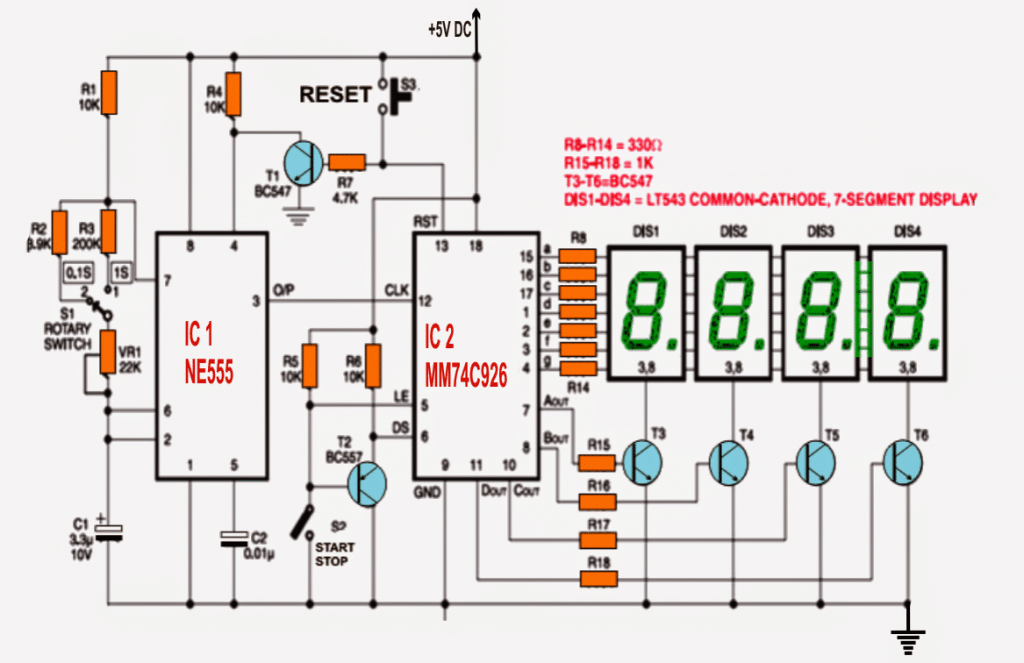
Circuit Diagram

A low logic signal on the latch-enable input pin 5 (LE) of IC2 latches the count in the counter module into the on chip set output latches.
In an event when switch S2 is switched ON, pin 5 is forced to go low and thereby the count figure is allowed to be saved in the latch section of the IC.
Display-select pin 6 (DS) ascertains if the figure on the counter or the stored count in the latch may be shown on the display or not.
In case pin 6 is held low the figure in the output latch section is enabled to get displayed, however if pin 6 is rendered with a high logic the count stored in the counter is illuminated over the connected display.
On an occasion when switch S2 is switched, the base of pnp transistor T2 is linked with ground ensuring that it begins operating. The emitter of T2 is rigged with DS pin of IC2.
Consequently, whenever switch S3 is switched ON, reset pin 13 of IC2 is coupled with negative through the transistor T1 making sure that the oscillator is inhibited from generating clock pulses. This operation is executed to implement a synchronization between IC1 and IC2.
At the first level, reset the module in order to enable the display to show ‘0000.’ Next disconnect switch S2 for the stop watch to initiate its counting the periods. In case you wished to inhibit the clocking of the chip, simply switch OFF the control S2.
The given rotary switch S1 may be opted for selecting the many different time intervals at the output of the astable multivibrator (IC1).
The proposed digital stopwatch circuit will work off a 5V supply inputs. The circuit may be easily fixed and built on a general-purpose PCB.
You may want to enclose the entire circuit in a metallic cabinet with slots built for four 7-segment displays, rotary switch S1, start/stop switch S2 and reset switch S3 in the dashboard plate of the selected encloser.
Main Specifications of the IC MM74C926:
- Supply Voltage (Vdd): 3V to 15V
- Logic Type: CMOS
- Current Consumption: Low power due to CMOS technology
- Clock Frequency: Up to 3 MHz at 10V
- Output Type: Common cathode 7-segment LED display driver
- Digits Supported: 4 digits (multiplexed)
- Package Type: DIP or SOIC
- Operating Temperature Range: -40°C to +85°C
Pin Configuration:
- Clock (CLK): Input for incrementing the counter.
- Reset (RST): Input to reset the counter to zero.
- Latch Enable (LE): Controls data latching for display updates.
- Display Outputs: Segment outputs (a, b, c, d, e, f, g) for driving a common cathode 7-segment display.
- Digit Select Outputs (D1-D4): Used for multiplexing the 4 digits.
Related Formulas:
Frequency of Oscillation (Internal Clock) can be calculated using the following formula:
f = 1 / (Rt * Ct)
- Rt: Resistor connected to the clock pin
- Ct: Capacitor connected to the clock pin
Current through Segment LEDs can be calculated using the following formula:
- Iseg = (Vdd - Vseg) / Rseg
- Vseg: Forward voltage drop of the LED segment (typically 2V for red LEDs)
- Rseg: Series resistor value for limiting current
Maximum Display Frequency (Multiplexing) can be calculated using the following formula:
- fdisp = fclk / 4
- fdisp: Effective refresh rate for each digit
- fclk: Input clock frequency
Sir I required same 99.99 sec stopwatch. Will it work for same?
Hi Sushil, yes you can achieve that using the above concept.
How can I achieve…what changes should I make in circuit.
You can implement it in the following way:
Initially keep the S2 switch open.
Select 1s for the S1 switch and adjust the VR1 preset to ensure a perfect 1 second clock pulses from pin#3 of the IC555 is generated.
Once the above is confirmed, now you can press the reset switch.
And finally, now you can turn ON the S2 switch to initiate the counting of the timing.
As soon as you see 99.99 on the display, you can instantly open S2 to freeze the counting and the display.
Hey, do you guys have kits available – IC 555 Based Simple Digital Stopwatch Circuit
Sorry, unfortunately we do not build or supply ready-made kits at this moment.
Hi Swagatam,
Please ignore the value of R2. I’ve seen it in the coments.
C2 is it polarized Capacitor, like electrolytic? or ceramic?
Hi Nelio,
C2 can be a non-polar, ceramic capacitor.
Hi Swagatam,
What is the value of R2?
Hi Nelio,
It’s 3.9K
https://alectronicx.blogspot.com/2011/07/ic-lm555-4-digit-counter-ic-mm74c926.html
Please tell me how to calculate components like resistors and others??
You can refer to this article:
https://www.homemade-circuits.com/how-to-connect-resistors-in-series-and-parallel/
Mm74c926 is not available, so which we used in alternative
I don’t think there’s any direct equivalent for this IC.
Hi.
Contacting you again to see if you can assist:
What I am looking to put together is a circuit that responds to a RF receiver.
The receiver uses 433Mhz, and has four relays inside the unit. ~ other relays could be added if needed.
I am using separating them so that battery 1 provides power to relay 1.
After receiving the first signal, RF1, Relay 1 then powers any consecutive relays/circuits.
I am looking for a timer that can be used so that after the second RF signal, RF2, is received:
1/ T1 starts timing (up or down) for determined (adjustable via R1/C1)
~ During T1 Event 1 is triggered (via circuit or relay)
3/ After T1 ends:
4/ T1 terminates, and T2 starts counting (up or down) for determined (adjustable via R2/C2)
~ During T2 Event 2 is triggered (via circuit or relay)
5/ After T2 ends:
6/ 4/ T2 terminates, and T3 starts counting (up or down) for determined (adjustable via R3/C3)
~ During T3 Event 3 is triggered (via circuit or relay)
[end]
I have scoured web sources for timers.
Some come close, some appear to be suitable but not quite.
I have no idea whether to use discrete 555 timers for each stage, or how to ensure they turn off at the end of the timing cycle.
This led me to think about decade counters, but I’m even more out of my limited depth.
Reading this, using IC MM74C926, I wondered if it could be modified somehow, perhaps altering R15-R18?
Any suggestions, pointers, tips, greatly appreciated.
Hi,
I have understood your requirement but it looks quite difficult.
I have a sequential transistorized timer circuit which switches ON T1, T2, T3…one after the other, but the problem is that once switched ON the transistors will not switch OFF.
So let’s say T1 switches ON after 2 seconds, then T2 switches ON after 2 seconds, then T3 switches ON after 2 seconds and so on….
so as you can see each transistor switches ON after a predetermined delay, but they don’t switch OFF once they are switched ON.
What is the resolution of the stopwatch? I need .01s
Sorry I am not sure about the resolution of the circuit
The project is good and I really love the work
Thank you very much!
Your work is great
The description of the MM74C926 functions in the Digital Stopwatch Circuit is interesting.
I’m trying to set up a 4 digit random events counter, updated every second, that shows the total number of events between one-second resets.
Apparently the total count, in my case for the period of the previous second, can be stored in the latch section whilst the count for the current second proceeds, without actually showing the progress of that count until the total is reached at the next rest event. Is that correct? And if so, what is the time relationship between the pulses needed, and their shape, for the reset and latch inputs? The datasheets do have some info at the back, but it’s not very clear.
Hi, I have not studied this IC so far, the post was submitted by another author, so at the moment providing a solution may be difficult for me.
how to connect 7 segments together if i have 4 seperate 7 segments for this circuit
I don’t think separate displays can be connected with this circuit, it has to be exactly as indicated in the diagram.
Hi
I need to display the time in seconds and milliseconds.
Format 99.99, example ….. 17.46 sec
How to enable decimal point between the 2nd and 3rd digit?
Any alternate for MM74C926 ?
Hi,
sorry presently I do not have the solution for this query.
Best Regards
sorry, but y can’t read the value of R2. Is it 3.9 k ?
yes it is 3.9K or you can modify it through a practical testing
Hi Swagatam,
I am not if you got the message posted on your contact site, so therefore I am sending it again.
I need a countdown timer with a relay which can be set to 1 to 5 minutes.
I would like the timer to show the preset time on 7 segments e.g. 3 min. = 180 or 3.00
When the time counts the 7 segments shall show the remaining time.
When the time is up the relay must switch off.
I don’t have Arduino and no skills in PIC programming yet.
Can you help me out with a circuit / schematic?
Thank you in advance,
Henrik
Hi Henrik, your earlier comment became lost in the contact page, which has some glitch.
as for your requirement, showing how much time is left digitally can be difficult since I do not have the idea with me at the moment.
however the relay mechanism can be easily implemented using a 4060 IC timer with a transistor relay driver circuit.
How to connect the battery. I am very much confused. Please help.
This circuit will display the result on all the four 7-segments only in seconds or on two 7-segments in minutes and on two 7-segments in seconds
It's a counter circuit, which will count the number of pulses fed by the IC555, so it has nothing to do with seconds, or minutes or hours….if the 555 is set with 1Hz pulse then the counter will on counting at the rate of 1 second per count until 9999 count is reached.
which DMM voltage test function am i expected 2use when testing the CD4017 output while it is oscillating is it vac or vdc bcos i used vdc when i got d 2v but wen i used vac i got 4v which of them is corect
it must be ON DC range…not AC
sir i am clocking the CD4017 with NE555 monostable pulse width modulator. And anoda NE555 astable multivibrator is then driving the monostable pwm through its trigger pin at a frequency of 478KHz(r1=1k, r2=100k, c=15pF) for the NE555 astable multivibrator. And r1=5.6k, c=330pF for the monostable pwm. But its control pin is held high with 10nF. Help me!
without disturbing the 10nF connect pin5 with the positive line and check the response.
sir i did! And i got aproximately 2v. that is 25% of supply value. Is anything wrong?
2V for a 8V supply is quite low, it could be due to low duty cycle from the oscillator, make sure the duty cycle of the oscillator is 50%, only then you can expect a 4V from the outputs.
I am using 80 pcs led in series with diode bridge and 10 ohm 0.5w resister (one at positive end and one at negative end) without any electronics capacitor and ppc capacitorto to drop down the voltage. But every day one , two .. led getting burned and I have to find and replace it ? PPC capacitor must needed and then use the number of led as per ppc cap specifications ??
without a capacitor it could be suicidal, a capacitor is a must.
led current will depend on the capacitor value, not the quantity
Sir, can you please some necessary changes for adding 93( as per https://www.homemade-circuits.com/2012/04/how-to-make-led-bulb-circuit.html ) led directly with ac supply. I have ultra bright 1/4 watt led.
Ram, no changes would be required, you may use the circuit as is.
How can one test the output voltage of a CD4017 with a DMM when d CD4017 is powered from 8v supply and clocked at a frequency of 478KHz and pin 10 and 15 are connected 2geda?
check it in the normal way across any of the output pin and ground, the result should be approximately 50% of the supply value.
Hai, the circuit diagram is in low resolution and not able to read the values of the components in the diagram. Could u pls post a little bit high resolution pic???
THanks…
Hi, thanks, please check it now.
Could u pls suggest any other alternative IC for MM74C926 which has the same working?? Bcoz the above IC is expensive in my area, Rs.550.
I have no idea about it presently, I'll try to find it and let you know