The discussed circuit is designed to discourage dogs from barking in the selected zone by the generation of a synchronized ultrasonic sound waves in response to a few initial barking of a particular dog.
The circuit when correctly optimized will produce a high pitched ultra sonic sound each time it senses a dog bark. Since the sound is in the ultrasonic range will be inaudible to humans, and audible to only dogs present in the vicinity.
How the Dog Bark Terminator Works

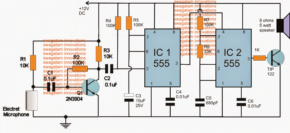
Note: Please use 1uF capacitor for C2 to ensure a foolproof triggering of the IC1 stage...
Parts List
- Resistors all 1/4 watt 5%
- R1, R3 = 10K
- R2, R4, R5, R7 = 100K
- R6 = 33K
- R7 = 1K
- Capacitors
- C1 = 0.1uF, disc ceramic
- C2 = 1uF/25V
- C3 = 10uF/25v
- C4, C6 = 0.01uF ceramic
- C5 = 680pF ceramic
- Transistors
- Q1 = 2N3904 or BC547
- Q2 = TIP122
Referring to the above shown dog bark inhibitor circuit, we can see three distinct stages involved, the sound sensor and preamplifier circuit using the Q1 and the electret MIC stage, the monostable stage using IC1 and the associated parts and the ultrasonic sound generator stage using the IC2 and the speaker driver stage.
Whenever a dog barks, the Mic detects it causing a sequential low and high pulse at the base of T1. T1 responds to this and produces an equivalent amplified signal across C2, which in turn triggers the pin#2 of the monostable IC1.
The above action forces IC1 to produce a high at its pin#3 for a period determined by the values of R5/C3.
This high at pin#3 of IC1 enables the reset pin#4 of IC2 to become active thereby allowing the astable IC2 to supply the ultrasonic pulse at its pin#3, which is appropriately amplified by the associated TIP122 transistor, driving the connected speaker.
The speaker vibrates at the specified amplified level throwing the ultrasonic sound in the direction where the dogs need to be driven away.
The above sound waves is supposed to fluster the dogs and cause a lot of disturbance in their ears due to its high pitched sound, and also due to its synchronized effect with the dog's own barking sequence.
Actually the above dog barking stopping device might respond to all types of high dB sound levels, however since it won't be audible to a human ear this will never be an issue, and may be ignored.
Making the Circuit more Sensitive
If you find the above dog barking prohibitor circuit not responding to barking signals or any sound distant signals correctly, then you must try upgrading the MIC stage with an IC based MIC amplifier stage as shown in the following image:

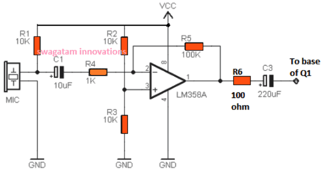
Once you build the above circuit, you can eliminate or remove R1, R2, C1 from the first circuit, and replace it with the mentioned op amp based MIC amplifier circuit and configure the C3 output from the op amp with the base of Q1.
This upgrade will ensure that the circuit responds appropriately even to weak sound signals, specifically dog barking sound during night time, and trigger the IC 555 stages for the intended results.
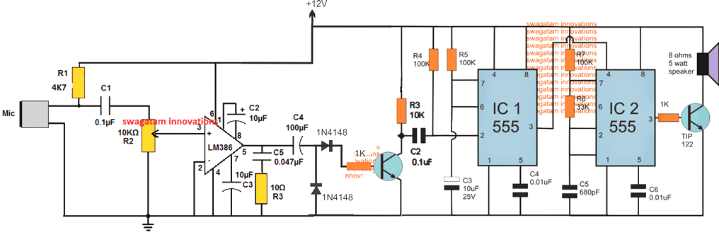
Increasing the Range over 50 Meters
To make the above design respond to dog barks at distances over 50 meters, the following modified idea could be tried.
However this circuit being extremely sensitive could get triggered by other forms of sounds in the vicinity.

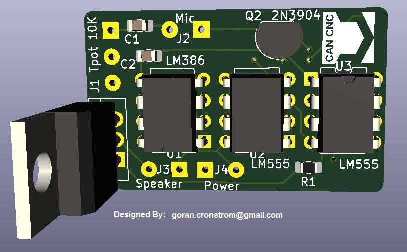
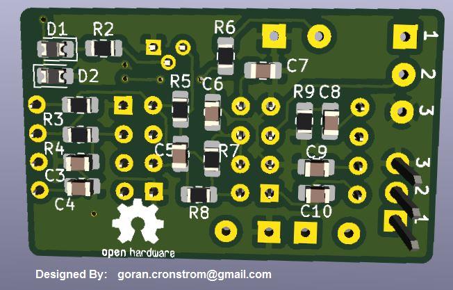
PCB Design


UPDATE: A Much Simplified Design
A simple transistorized circuit presented below can be used as effectively as the above designs for repelling dogs or any other animal away, from a distance.

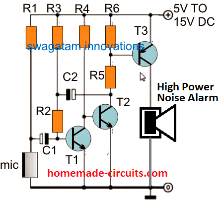
The parts list for the above design is shown below:
- R1 = 5k6
- R2 = 47k
- R3 = 3M3
- R4 = 33K
- R5 = 330 OHMS
- R6 = 2K2
- C1 = 0.1uF
- C2 = 1uF/25V
- T1, T2 = BC547
- T3 = TIP127
- D1 = 1N4007
- Mic = electret condenser MIC.
If you wish to use some other form of deterrent instead of the indicated high power alarm, you can replace the speaker with a relay and connect the desired load with the relay contacts. The relay based design is demonstrated in the following diagram:

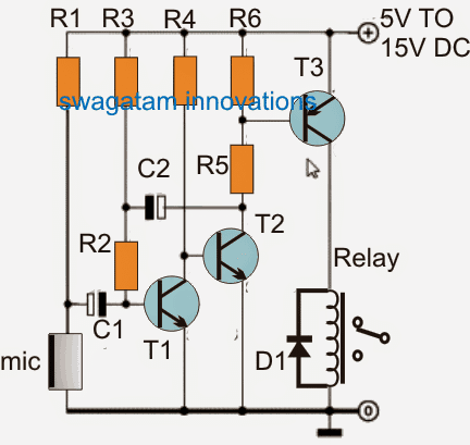
The parts list will be the same as above, except the T3, which can be replaced with BC557 transistor.
How it Works
As soon as a relatively loud noise such as a dog barking sound is detected by the MIC, the signals are amplified by the subsequent BJT stages, which activates the relay momentarily. This momentary delay of the relay activation is determined by the value of C2, which can be adjusted to best suit the application.
The relay contacts can be hooked up with a suitable high frequency circuit, such as an electronic dog whistle.
Improving Further
In the above design, the relay can be eliminated, and the T3 collector output can be directly used to activate the IC 555 frequency generator circuit, as shown in the following figure:

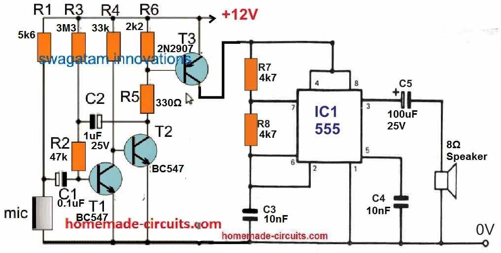
Dog Deterrent Circuit
Are dogs from the neighborhood constantly digging up your front lawn? The following high-pitched screamer can effectively deter them!

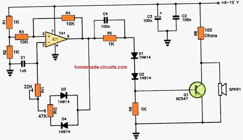
The IC1 (Integrated Circuit 1) is configured as a high-frequency oscillator, producing narrow pulses. You have the flexibility to adjust the frequency using RV1 and fine-tune the mark-to-space ratio with RV2.
IC1's output is channeled to the base of Q1 through R5 and D1-D2. The pulses at the collector of Q1 drive SPKR1, which is a piezo horn tweeter.
These sounds operate at frequencies well above our hearing range and are exceptionally loud, making them audible to dogs and other garden pests with four legs.
The inclusion of diodes D1 and D2 serves to enhance the turn-on voltage for Q1 because IC1's output doesn't reach all the way down to zero volts.
To achieve the best results, some trial and error with RV1 and RV2 settings may be necessary to optimize the device's performance.
High Power Push-Pull Dog Repellent Circuit (Tested)
The ultrasonic dog repellent circuit shown below is a highly effective design due to its H-bridge configuration, which generates a powerful push-pull action on the attached ultrasonic transducer.
The push-pull mode creates a pumping action on the transducer causing massive thrusts on the generated ultrasonic pulses.
This circuit was practically tried on dogs and cats with positive results. The testing procedure required a lot of hard work and dedicated effort, which was thoroughly implemented by Mr. Emad, who is an avid reader of this blog and great electronic enthusiast.
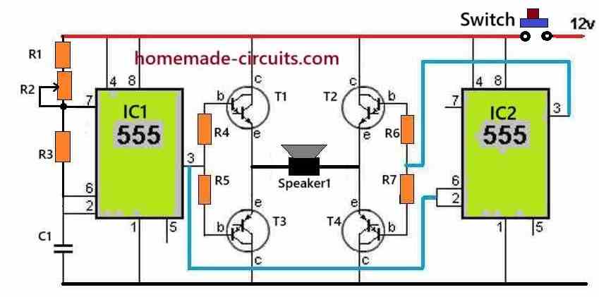
Circuit Diagram

How the Circuit Works
The IC1 is configured as a normal IC 555 astable circuit which generates square wave pulses at its output pin#3.
The resistor R1 along with the R2 pot value determine the frequency of IC1 output.
This output from IC1 is applied to T1, T3 driver transistors of the H-Bridge configuration.
This frequency at pin#3 of IC1 is also fed to the pin2 and pin6 of another IC2 555 stage.
This 555 IC2 is configured as a set-reset circuit, which works efficiently to enable the correct functioning of the H-bridge transistor driver.
The output pin#3 of IC2 is connected with T2, T4 which forms the other set of driver transistors of the H-bridge circuit.
The IC2 ensures that during the ON periods of IC1 pin#3, the IC2 pin#3 is OFF, and vice versa.
This ensures a safe operation of the H-bridge transistors which always operate diagonally, causing an alternate push-pull or reverse forward conduction of the load, which is a transducer in this circuit.
The push pull action of the transducer diaphragm causes powerful thrusts on the generated pulses which ultimately helps to create a strong repelling action on animals like dogs and cats.
Parts List
- R1 1k 1/4 watt = 1
- R3 4.7k 1/4 watt = 1
- R4-----R7 200 ohms 1 watt = 4
- R2 20k pot = 1
- Capacitor C1, 3300 pF = 1
- Transistors, T1, T2 = TIP35
- Transistors, T3, T4 = TIP36
- IC1, IC2, IC555 = 2
- Push Button 5 amp = 1
- Speaker1 is a 8 ohm High Power Tweeter, as shown below = 1
Tweeters used in the above prototype