An AC mains solid state relay or SSR is a device which is used for switching heavy AC loads at mains level, through isolated minimal DC voltage triggers, without incorporating mechanical moving contacts.
In this post I have explained how to construct a simple mains operated solid state relay or an SSR circuit using a Triac, BJTs, a zero crossing opto coupler.
Advantage of Solid State SSR over Mechanical Relays
Mechanical type of relays can be pretty inefficient in applications which require highly smooth, very swift and clean switching.
The proposed circuit of an SSR can be built at home and used in places which require truly sophisticated load handling.
A mains 220 V solid state relay circuit with in built zero crossing detector is I have I have explained in this article.
The circuit is very easy to understand and build yet provides with useful features like clean switching, free from RF disturbances, and able to handle loads up to 500 watts.We have learned a lot about relays and how they function.
We know that these devices are used for switching heavy electrical loads through external isolated pair of contacts, in response to a small electrical pulse received from an electronic circuit output.
Normally the trigger input is in the vicinity of the relay coil voltage, which may be 6, 12 or 24 V DC, while the load and the current switched by the relay contacts are mostly at the levels of AC mains potentials.
Basically relays are useful because they are able to toggle heavy connected to their contacts without bringing the dangerous potentials in contact with the vulnerable electronic circuit through which it is being switched.
However the advantages are accompanied by a few critical drawbacks which cannot be ignored. Since the contacts involve mechanical operations, sometimes are quite inept with sophisticated circuits which require highly accurate, quick and efficient switching.
Mechanical relays also have the bad reputation of generating RF interference and noise during switching which also results in its contacts degradation with time.
For a MOSFET based SSR please refer to this post
Using SCR or Triac for Making SSR
Triacs and SCRs are thought to be good replacements in places where the above relays prove inefficient, however these too may involve RF interference generation problems while operating.
Also SCRs and Triacs when integrated directly to electronic circuits require the circuit’s ground line to be connected with its cathode, which means the circuit section is now no longer isolated from the lethal AC voltages from the device – a serious drawback as far as safety to the user is concerned.
However a triac can be very efficiently implemented if the above discussed couple of drawbacks are completely taken care of.
Therefore the two things which must be removed with triacs, if they were to be efficiently replaced for relays are, RF interference while changeover, and the entry of the dangerous mains into the circuit.
Solid State relays are designed exactly with the above specifications, which eliminates RF inference and also keeps the two stages completely aloof from exh other.
Commercial SSRs can be very costly and aren’t serviceable if anything goes wrong. However making a solid state relay all by you and using it for the required application can be just what the “doctor had ordered.”
Since it can be built using discrete electronic components becomes completely repairable, modifiable and moreover it provides you with a clear idea regarding the internal operations of the system.
Here we will study the making of a simple 220V solid state relay.
How it Works
As discussed in the above section, in the proposed SSR or solid state relay circuit design the RF interference is checked by forcing the triac to switch only around the zero mark of the AC sine phase and the use of an opto coupler ensures that the input is kept well away from the AC mains potentials present with the triac circuit.
Let’s try to understand how the circuit functions:
As shown in the diagram the opto coupler becomes the portal between the trigger and the switching circuit. The input trigger is applied to the LED of the opto which illuminates and makes the photo-transistor conduct.
The voltage from the photo-transistor passes across the collector to the emitter and finally reaches the triac’s gate to operate it.
The above operation is pretty ordinary and is commonly associated with the trigger of all Triacs and SCRs. However this may not be enough to make the RF noise eliminate.
The section comprising the three transistors and some resistors are especially introduced with the view of checking the RF generation, by ensuring that the triac conducts only in the vicinity of the zero thresholds of the AC sine waveform.
When AC mains is applied to the circuit, a rectified DC becomes available at the collector of the opto transistor and it conducts as explained above.
However the voltage at the junction of the resistors connected to the base of T1 is so adjusted that it conducts immediately after the AC waveform rises above the 7 volt mark. For so long the waveform stays above this level keeps T1 switched ON.
This grounds the collector voltage of the opto transistor, inhibiting the triac from conducting, but the moment the voltage reaches 7 volts and nears zero, the transistors stop conducting allowing the triac to switch.
The process is repeated during the negative half cycle when T2, T3 conducts in response to voltages above minus 7 volts again making sute that the triac fires only when the phase potential nears zero, effectively eliminating the induction of zero crossing RF interferences.
Circuit Diagram of Triac based 220 V AC Solid State Relay Circuit


Parts List
- R1 = 120 K =1,
- R2 = 680K =1,
- R3 = 1 K =1,
- R4 = 330 K =1,
- R5 = 1 M =1,
- R6 = 100 Ohms 1 W =1,
- C1 = 220 uF / 25 V =1,
- C2 = 474 / 400 V Metalized Polyester =1,
- C3 = 0.22uF/400V PPC =1,
- Z1 = 30 volts =1,
- T1, T2 =BC547B =2,
- T3 = BC557B =1,
- TR1 = BT 136 =1,
- OP1 = MCT2E or similar =1,
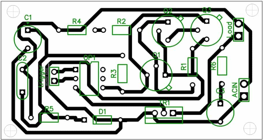
PCB Layout

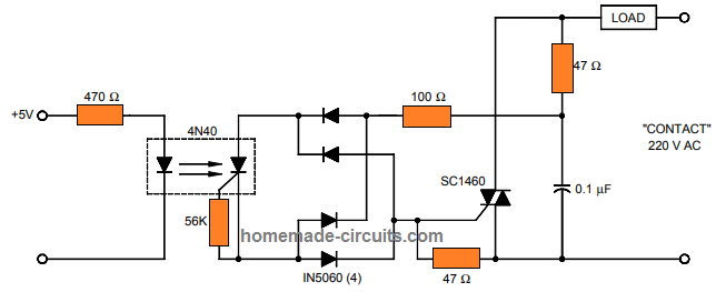
Using SCR Opto-Coupler 4N40
Today with the advent of modern opto-couplers, making a high grade solid state relay (SSR) has really become easy.
The 4N40 is one of these devices which uses a photo SCR for the required isolated triggering of an AC load.
This opto-coupler can be simply configured for creating a highly reliable and effective SSR circuit. This circuit can be used for triggering a 220V load through a thoroughly isolated 5V logic control, as shown below:

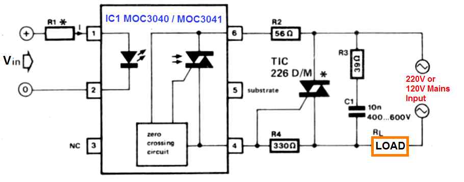
220 V SSR Circuit Using MOC3020 Opto-coupler IC and Triac
The ICs MOC3040 or MOC3041 are similar to a normal opto-coupler where the typical phototransistor is substituted by a phototriac (100 mA/400 Vat 25°C).
The main feature of this IC is that it practically allows all forms of silicon-controlled rectifiers (SCRs) and triacs to be employed in the circuit, which usually may not be possible with phototransistor based opto-couplers.
Determining the type of triac for making a 220V operated solid state relay is possible, based on the kind of load to be operated by the relay.

Considering that the SSR load is resistive, the triac TIC 226D/400 V can be used satisfactorily.
In case, an inductive load is specified for the load, a 630 V triac may be required, for example, a type TIC 226M, can be necessary.
Remember the working voltage of capacitor C1 should match the specs of the triac used.
The input side resistor R1 can be determined depending on the level of the input voltage, Vin. Its value can be evaluated using the following formula:
R1 = 1000 (Vin - 1.3)/Ioc.
In this equation Vin will be in volts, R1 is in ohms, and Ioc will be in mA, which indicates the current through the LED in the MOC opto-coupler.
If we consider the LED side input of the opto coupler to be Vin = 12 V, and the current Ioc = 30 mA (which are the standard specifications of the MOC 3040 opto coupler), the worked out value of R1 will be equal to 356 Ohms, and we can round it of to a practically feasible value of 330 Ohms.
In the MOC 3041 the current specification Ioc of the LED is simply 15 mA, which means that, practically it may be possible to allow the R1 limiting resistance value to be around 680 Ohms.
The maximum current this 220V solid state relay can handle is approximately 8 Amps, for higher power you can change the triac accordingly
Image courtesy: Farnel
Hi Swagatam,
In the last circuit of Triac with MOC3041, Is there anything like Pin 1 should connect with load and Pin 2 should connect with Line for BT136. Or Can we connect vice versa also?
Hi Sriram,
Pin1 and pin2 are supposed to be connected with a DC input signal input for switching the triac side load correspondingly.
Do you want to connect the signal from the AC side? In that case you will need to use a high value resistor for R1.
Pin1 and pin2 can be connected any way round across the AC 220V side
Hi
Which relays can be used to protect against failures in synchronization? PV grid inverter
Hi,
I am not exactly sure about it.
Sir,
Wish you a Happy 2023.Thank you for all your advice and information.
Can I use a MOC 3041 in place of a MOC 3020 directly? If not what changes should I consider.
Thank you.
Suren Wijesekera
Thank you Suren, wish you too a Happy New Year!
Yes you can replace MOC3020 with MOC3041 directly. No changes would be required.
THIS CIRCUIT IS INTERESTING BUT PLEASE WHERE THE NC AND NO CONTACTS OF THE RELAY. CAN WE USE THIS FOR AUTOMATIC VOLTAGE STABILIZER
There’s no NC contact, only NO contact across the load terminals. You can use it for stabilizer application also.
HI Mr. s. thank you for your kindness to answer me . Actually I interest to electronics . I work on it for years. I found many pieces of old scr in my friend workshop. they are so big I think 150 amps. I imagine they used them for controlling kids electric cars. now I like to use them as a ssr controler. I need some help . first of all I know I should parallel them to use as a TIC , but I do not know if it works instead , If it works you think I can use it in your above diagram. ???? . can you help me. thanks.
Hi, yes you can use your SCR in the above shown circuits, but being an SCR and not a triac, it will only work with 50% of the AC cycles….
hi . I have many If I parallel two scr in reverse way , again I can use it as a triac? . how to calculate the voltage and miliampers to fire two of them simultaneously??? . is it possible ? my scr is
BSTL3590 . large , 250 amps and 1.2 kv. can yo help me ?
thanks for your help.
Hi, I am not entirely sure, but you can give it a try. You can connect the two gates with each other, having a 1K resistor in series with each of the SCR gates. After this you can try switching the common end of the resistors with a DC signal and check the response.
Thanks for all this information , I was wondering if could use one MOC3040 to drive two Triac to control two AC separate lines?
can use the Triac+MOC3040 for both DC/AC load control?
do you suggest using a fuse for Triac protection ?
You are welcome! Yes, all those functions are possible using triac and MOC optocoupler. A fuse is always a recommended device with all AC circuits, so it must be included.
Can I use “Circuit Diagram of Triac based Solid State Relay Circuit” with a 2HP water pump?
Yes you can use it!
hi.
What can I use instead of sc 1460?
You can use any standard triac.
IS THERE ANY SIMPLE SOLID STATE DC RELAY CIRCUIT WHICH OPERATES FROM 6VOLT TO 14VOLTS.
NOTE- PURPOSE IS FOR FLASHING THE LED AND LOAD WILL BE APPROX 60 WATTS @ 12.8 VOLTS
Use a BJT or MOSFET with the output of any opto coupler, that will fulfill your requirement.
Hello Mr. Swagatam,
Hope you are good and safe. Am making a solid state relay with MOC3021 and BT136. And planning to integrate with PIR sensor. What my query is how to toggle it between sensor mode and always “LIGHT ON” mode.
Previously I made the circuit with electromagnetic relay and directly connected the light to phase line with a two way home switch. So I can toggle between sensor and always ON.
Now connecting the TRIAC with the light, I guess I cannot connect light directly to the switch and it may damage the triac. Kindly help.
Thanks Mr.Sriram, You can simply connect a switch between the (+) and OUT pins of the PIR to bypass the positive directly to the MOC input, and this will enable always Light ON or PIR mode operation.
Sir, is this circuit suitable for replacing a contactor on an ATS system used To transfer the load between the mains and a generator? About 50 Amperes.
No, this circuit cannot be used as a changeover relay.
Is it possible to control 220vac 5000 to 10000 watt heater with SCR or other solid state device?
Yes, definitely possible!
Swagatam, can you help me get started, components, circuits etc.
Thanks
Jim, you can try the following concept:
https://www.homemade-circuits.com/how-to-make-25-amp-1500-watts-heater/
All capacitors are 400V rated and the resistors are 1/4 watt 5%
Hi,
How to modify this circuit to use it with 120v 60Hz?
Does it need to be modified?
Thanks.
No, it does not require any specific modifications for 120V. This is unrelated, I think there should have been a diode 1N4007 in between R3, and C2 line, cathode towards R3…And aslo a 33 ohm 1 watt in series with the input AC line to safeguard the zener!
Hi Sir
Thanks for the post
May I know the value of C3?
Thanks
Hi Ngo, You can use 0.22uF 400V for C3
Hi Swagatam
I am looking for an SSR which can handle 100A 12V load, input voltage 6 – 12V.
I assume the above circuit is suitable for AC main loads.
Hi Abu-Hafss, if the shown triac is rated adequately as per the specified load current then surely it can be applied for the same.
Hi Swagatam
I have read somewhere that DC SSR should not have zero crossing detector and should have an SCR instead of traic.
Hi Abu-Hafss, the above circuit is designed for controlling AC loads at mains level, therefore a zero crossing becomes advantageous for suppressing noise and interference.
That's what I am asking, can you offer me some design of DC SSR without zero crossing detector capable of handling 100A at 12V.
…if possible i'll try to design and publish soon.