We all know what a dice is and how manually a dice is shuffled and thrown to get a random number. In older times when we did not have computer games or mobile games, we used to play with various indoor games that required tossing a cubical thing called dice having 1 to 6 dots printed over each of its 6 surfaces.
When the dice is shuffled inside closed palm and thrown on the ground, we have this cubical thing rolling and dancing on the floor until it settles down and one of the surfaces is turned up to show a random number of dots to the players.
In this post I have explained 5 different ways to create an electronic version or a digital version of a dice which can be used to get random numbers between 1 to 6 through either LED display or digital display.
1) Electronic Dice using IC 4017
In the first design I have explained how to make an electronic dice using the IC 4017.
The circuit diagram for the electronic dice using the IC 4017 is shown in the following diagram.
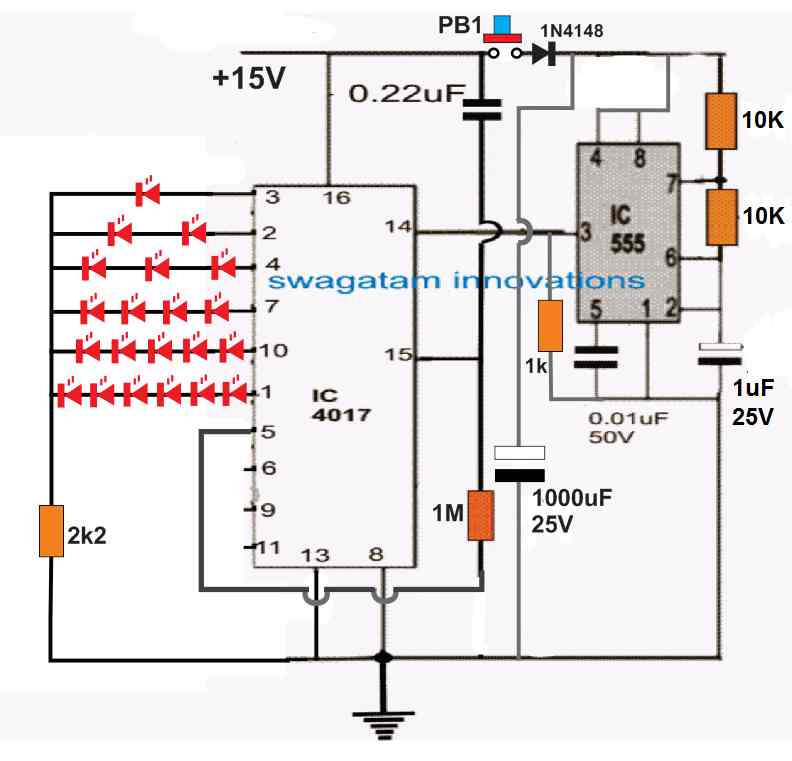
The working of this 4017 IC based dice circuit is pretty simple. We know that when clock signals are fed at the pin#14 of the 4017 IC, the output of the IC starts sequencing forward from pin#3 towards pin#11.
But since here the pin#5 is connected with the reset pin#15 of the IC, the outputs are able to sequence only up to pin#1 and return back to pin#3 for a new sequence.
This sequencing keeps repeating as long as a clock frequency is applied at pin#14 of the IC.
This clock frequency is applied by the IC 555 which is configured like a free running astable multivibrator with a high frequency output.
When the push button PB1 is pressed for a brief moment and released, the capacitor 1000uF charges up fully and powers the IC 555, the IC 555 uses this power and remains switched ON for a few seconds, allowing the IC 4017 to sequence rapidly across the output pins.
When the charge inside the 1000uF capacitor is fully used up, the IC 555 turns OFF and stops providing the clock pulses to the IC 4017. This output sequencing of the IC 4017 now halts to a randomly selected output of the IC between pin#3 and pin#1.
The outputs of the IC can be seen wired with series LEDs which illuminate and indicate the random dice number when the sequencing stops.
2) Simplified 4017 Dice
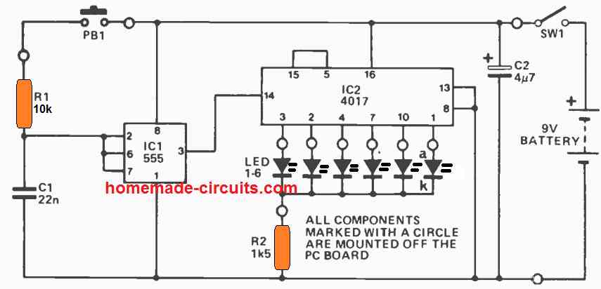
The working of the above shown IC 4017 electronic LED dice circuit is the same as the first diagram, except the number of LEDs used, which has restricted to one LED per output, for the IC. When the push button is pressed, the IC 555 starts oscillating at a very high speed, causing the IC 4017 output to sequence from pin#3 to pin#1 at an equivalently high speed. The high speed sequencing makes it difficult for the user to realize exactly where the sequence would stop after the push button is released.
Thus, when the push button is released, the sequencing abruptly stops at some random output pin of the IC denoting the respective dice number, in accordance with the LED indication. For example if the LEDs are marked from 1 to 6, with respect to the output pin#3 to pin#1, then if suppose the sequence stops at pin#7, illuminating the LED at pin#7 would indicate the dice number of 4, and so on.
3) Dice Circuit using CMOS ICs
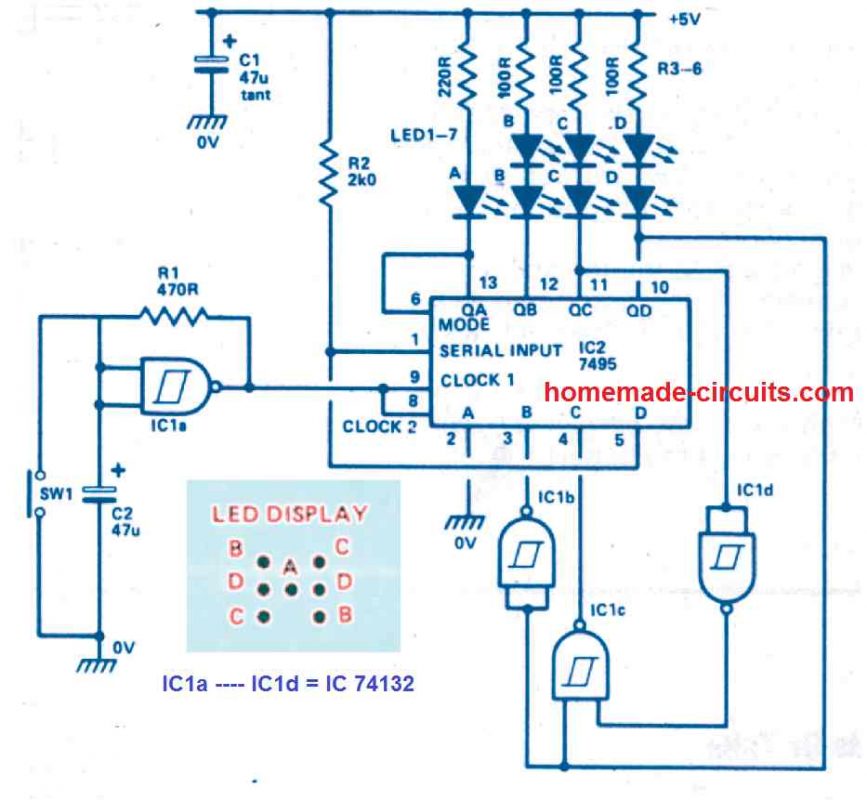
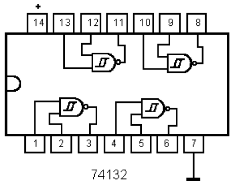
The next electronic dice circuit generates a genuine dice display through the use of just a couple of ICs, a 74132 and a 7495.
When the push button switch SW1 is pressed momentarily, the dice circuit begins counting rapidly, and as soon as the push button is released, the IC stops counting and illuminates the LEDs such that they represent any one number between 1 and 6 randomly.
Circuit Description
The 7495 is actually a 4-bit parallel-access shift register. This chip could either work like a shift-register or serve as a parallel loaded at inputs A-D.
The mode control unput controls the above mentioned two functions of the IC 7495.
When the mode is in the high state, data is delivered into Qa - Qd via inputs A- D through the subsequent negative-going clock edge.
When the mode is in the low state, data is transferred over Qa - Qd through the subsequent negative-going clock edge.
By attaching the mode control to Qa ensures that the register alternately conducts between load and shift, enabling the input word to be a function of the existing output word.
Using some basic logic, the register is finally designed to implement count numbers that switch the LEDs randomly in a dice display, to imitate the random numbers of a real cubical type dice.
Remember that the LEDs are illuminated whenever the outputs are low logic.
IC1a is configured like a standard Schmitt oscillator that supplies clock pulses to the register.
Switch SW 1 is used to stop the oscillator and inhibit the counting process. Therefore, to get the dice number, the user has to press the SW1, which freezes the count and provides the random dice number to the user.
When power is first switched ON, the register may possibly commence with an invalid count, however after a few clock periods it will create a legitimate count after which it will continue to be in that specific sequence
4) Dice Circuit using Digital Display
The next digital dice circuit produces the dice results over a 7 segment common anode display module.
Pressing the button PB1 initiates the counting, and as soon as the the button is released we a get number on the 7 segment display which may be a random number between 1 and 6.
How the Circuit Works
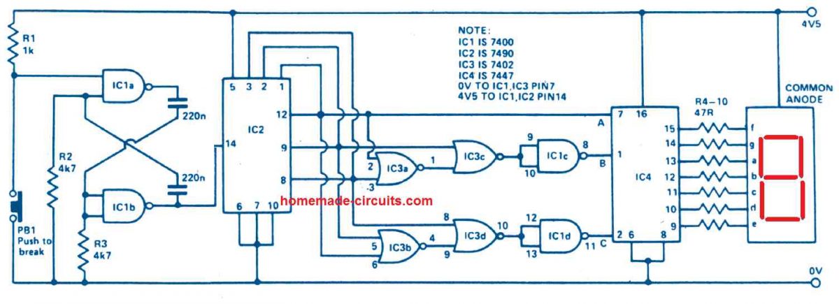
IC1a and IC1b is designed to operate like an oscillator producing a frequency output of some kilohertz. The output is applied to the IC 7490 which is a binary counter and is configured to generate an output of 0 to 5 in BCD.
To ensure that the digital dice behaves exactly like a cube dice, the digital display must be capable of producing the reading from 1 to 6 and not 0-5.
Also, whenever the IC 7490's outputs are all '0's, the 7 segment LED display must indicate the number 6.
IC1c, d and IC3 are used exactly to implement this job, for changing an output of 000 from IC2 to 110 (b).
IC4 is a BCD to 7-segment decoder which is configured to run the 7-segment LED display by means of the current limit resistors R4-R10.
The switch PB1 is a push-to-off switch, which must pushed and then released momentarily to get the random digital dice number on the digital display.
5) Using IC 7400
