Everyone is familiar with the mechanical measuring tape made of wood to measure human height. We offer you an original electronic version that operates based on the use of ultrasound.
The circuit can be also used to measure distances between two surfaces or walls.
Basic Working
Ultrasounds are part of the range of sounds that are inaudible to the human ear due to their frequency, which is higher than 25 kHz. However, they are indeed sound waves whose variations in compression propagate from one medium to another at the same speed as audible sound.
It should be noted that this speed is 330 m/s at around 20 degrees Celsius. The distance between two consecutive pressure maxima is called the wavelength, and it primarily depends on the frequency of ultrasounds.
In the present application, the frequency is 40 kHz, corresponding to a period of 25 microseconds. As a result, the wavelength (λ) is given by the formula λ = V × T, which is approximately 8.25 mm at 20°C.
Similar to sound, ultrasounds reflect off obstacles. By accurately measuring the time it takes for an ultrasonic signal to travel back and forth (in the form of an echo) between a point and an obstacle, it is easy to determine the distance (d) between the source and the obstacle.
In this case, if dt represents the measured time, the relationship can be written as 2d = V × dt, from which the value of d can be derived. It is this property of ultrasounds that is exploited in the electronic measuring tape circuit I have I have explained in this article.
Circuit Diagrams
Operating Principle
A device consists of an ultrasonic transmitter and receiver, in the form of a capsule, placed side by side and facing downwards.
They are located in a plane separated from the ground by a distance of 2 meters. Ultrasound waves are reflected off the individual's skull, whose size we want to measure.
These signals are emitted periodically.
A timing device measures the time, and thus the distance, between the position plane of the ultrasonic transducers and the individual's skull.
This distance, determined by proportional time counting, is subtracted from 2 meters.
For example, if this distance is 17cm, the individual has a height of 1.83m.
The height indicator is directly readable through three 7-segment displays placed in front of the eyes, in a second enclosure.
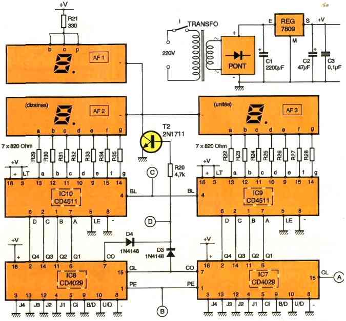
Power Supply
The energy is drawn from the 220V mains through a transformer activated by switch I.
On the secondary side, an alternating potential of 12V is obtained, which is rectified by a diode bridge. The capacitor C1 performs initial filtering.
On the output of a 7809 regulator, a constant potential of 9V is obtained, and the capacitor C2 provides additional filtering.
The capacitor C3 couples the power supply to the rest of the circuit.
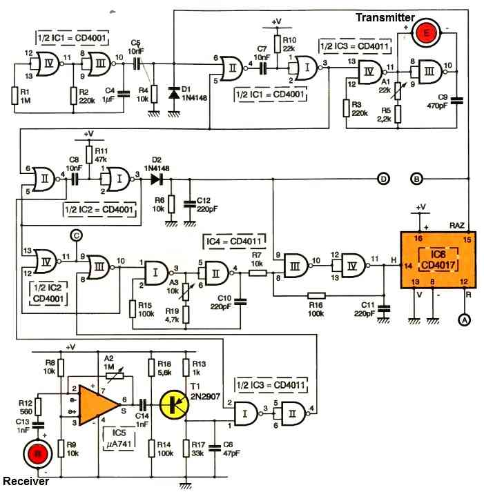
Time Base
The NOR gates lll and IV of IC1 form an astable multivibrator.
Such a circuit generates square wave pulses on its output, with the period primarily determined by the values of R2 and C4.
In the present case, this period is approximately 0.5 seconds.
It forms the basis for the periodicity of the measurements.
The capacitor C5, resistor R4, and diode D1 constitute a timing device.
On the cathode of D1, brief positive pulses are observed every 0.5 seconds, resulting from the rapid charging of C5 through R4 during the rising edges of the signals generated by the multivibrator.
Command of the ultrasonic signal
The NOR gates I and II of IC1 are configured as a monostable flip-flop. For each command pulse, a high state is observed at the output of this flip-flop, the duration of which is mainly calibrated by the values of R10 and C7.
In the present application, this duration is set to 150 microseconds.
Periodic emission of ultrasound
The NAND gates III and IV of IC3 are configured as a command-driven astable multivibrator. As long as the control input remains low, the output stays low as well.
However, if a high state is presented at the control input, square wave pulses are observed at the output. By adjusting the adjustable component A1, the period of these pulses is set to 25 microseconds, which corresponds to a frequency of 40 kHz.
The ultrasonic transmitter transducer, based on piezoelectric technology, is connected to the inputs/outputs of the NAND gate III.
At the terminals of this transducer, square wave pulses of 40 kHz frequency are obtained, but with an amplitude (i.e., the difference between maximum and minimum) of 18V, which increases the intensity of the ultrasonic transmission.
This transmission occurs periodically, every half-second, and lasts for 150 microseconds, equivalent to six cycles. As a result, the total wavelength of the wave traveling through space is 6λ, approximately 50 mm.
Reception of Signal
The reflected echoes are captured by the receiving ultrasonic transducer. The corresponding signals are routed to the inverting input of a 741 op-amp through C13 and R12.
It should be noted that the receiving transducer actually reacts twice during each measurement cycle: first, during transmission, due to the proximity of the two transducers, and second, when receiving the reflected ultrasonic echo.
Amplification
Amplification is necessary for the signal corresponding to the reflection echo because it is significantly attenuated. This task is carried out by the .741 op-amp, specifically the IC5 reference.
Its direct input is subjected to the half supply voltage thanks to the voltage divider formed by equal-value resistors R8 and R9. In fact, this potential is recorded as the resting state at the output of the operational amplifier.
The gain of the op-amp can be adjusted using the slider of adjustable component A2.
The resulting signals are routed to the base of the PNP transistor T1, whose biasing is such that in the absence of signals, the collector is at zero potential.
However, the ultrasonic signals received by the transducer manifest as brief positive pulses at the collector of T1, with the 40 kHz carrier frequency being filtered by the capacitor C6.
Elimination of the transmission signal
Since the receiving transducer is also sensitive to the ultrasonic signal corresponding to the transmission, it is clear that this signal is not of interest and needs to be eliminated.
To achieve this, at the beginning of each cycle, the monostable flip-flop formed by the NOR gates I and II of IC2 presents a high state on its output for a duration of 330 microseconds.
This results in a low state of the same duration at the output of NOR gate II.
This low state disables the NAND gate I of IC3, so on the output of NAND gate II of IC3, a low state is registered even if the receiving transducer reacts to the transmission signal.
However, once the 330 microseconds of neutralization have elapsed, the perception of the return echo results in a positive pulse on the output of the NAND gate II of IC3.
Materialization of the round-trip duration of the ultrasonic signal
At the beginning of the measurement cycle, the output of the monostable flip-flop formed by the NOR gates I and II of IC2 presents a positive edge.
This edge is directly connected to the Set input of an R/S flip-flop formed by the NOR gates III and IV of IC2.
As a result, the output of this flip-flop immediately goes high. The output of the NAND gate II of IC3 is connected to the Reset input of the same flip-flop.
When receiving the return echo, the high state delivered by the NAND gate II causes the R/S flip-flop to be reset.
Ultimately, the duration of the ultrasonic signal's round-trip is manifested by the high state at the output of the R/S flip-flop.
During the entire duration of the high state on the output of the R/S flip-flop, the astable multivibrator formed by the NAND gates I and II of IC4 enters oscillation.
It delivers square wave pulses, which are immediately taken into account by the Schmitt trigger formed by the NAND gates III and IV of IC4, along with their associated resistors R7 and R16.
These pulses are then routed to the clock input of a CD4017 decimal counter. On the carry output of the counter, a signal is generated with a frequency that has been divided by 10. This frequency will be used for the countdown.
It is thus possible to calculate the frequency, and hence the period, of the oscillations delivered by the multivibrator, which can be adjusted using the slider of adjustable component A3.
If "d" is the distance between the top surface of the individual's skull and the transducers, the value to subtract from 200 (centimeters) is precisely "d" (expressed in centimeters).
The output of the CD4017 (IC6) must generate "d" periods, while the multivibrator generates 10 x "d" periods. The distance that the ultrasonic waves must travel is 2d.
This corresponds to a duration: t = 2d / (100 x 330) (s). The duration of one pulse, which is the period delivered by the multivibrator, is then t / (10 x d), denoted as T = 2d / (100 x 330 x 10 x d) ≈ 6 microseconds (us), which corresponds to a frequency of 165 kHz.
Counting
The implemented counters are CD4029 ICs, specifically assigned to the units and tens positions. Their Binary/Decade input is held at a low state, allowing counting in Binary-Coded Decimal (BCD) mode.
In fact, it would be more appropriate to refer to it as "counting down" since their Up/Down inputs are permanently connected to a low state. At the beginning of the measurement cycle:
- The Reset input of the decimal counter IC6
- The Preset Enable inputs of IC7 and IC8 receive a brief positive pulse (marked as B), resulting in their reset or initialization. Subsequently, the countdown begins. It stops when the reflection echo hits the ultrasonic receiver transducer.
- If this echo doesn't occur, due to the absence or distance of an obstacle, the counters, while continuing their countdown, eventually reach the -00- position, which is indicated by a low state on the %carry Out outputs of both counters.
- This specific position causes the control input of the NAND trigger gate III of IC4 to be held at a low state.
- The countdown automatically stops, and the counters remain locked in this 00 position. We will see later that another consequence of this extreme situation is the non-display of the result.
On the other hand, during the start of the countdown, without specific precautions, the counters cannot begin their operation because the Carry Out outputs, in a low state, neutralize the NAND trigger gates III and IV of IC4.
This problem is solved by the diode Dy, whose anode, at the beginning of the cycle and for 330 microseconds, is held at a high state thanks to the monostable flip-flop formed by the NOR gates I and II of IC9.
From the beginning of the countdown, i.e., from the 9 9 position onwards, the Carry Out outputs take over and switch to a high state.
Display
The BCD outputs of the two counters are connected to the A, B, C, D inputs of 7-segment BCD decoders.
Each decoder has seven outputs directly connected to the segments of the common cathode displays through current-limiting resistors.
The display AF1 constantly shows the digit "1" followed by the decimal point. The extinguishing of the display (including AF1) is explained in the following paragraph.
Display Shut OFF
During the counting, the output of NOR gate IV of IC2, which feeds into the RS flip-flop, is in a low state.
As a result, the Blanking inputs of decoders IC9 and IC10, which are also held at a low state, temporarily turn off the display of AF2 and AF3.
This prevents the observer from seeing all the segments lighting up for a few milliseconds during counting, causing retinal persistence.
Similarly, in case the reflection echo is not detected and the common anode point of D3 and D4 is held at a low state due to the counting limit position, transistor T2 is turned off.
The display then disappears from all three displays, indicating to the user of the measurement device that the measurement is not being conducted correctly.
Construction using Printed Circuit Boards
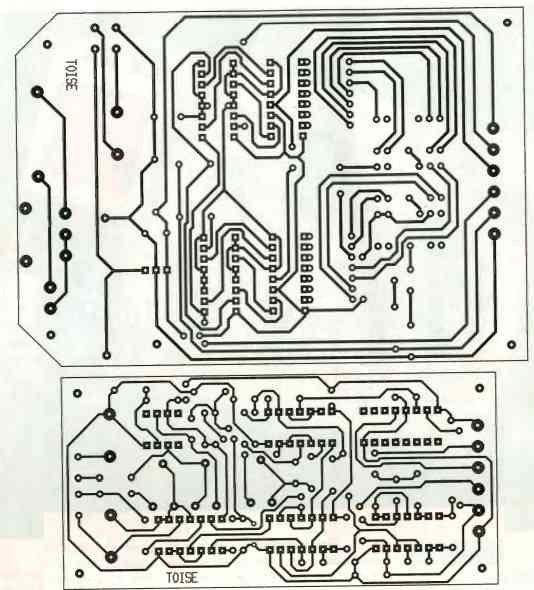
For the US module, the track configuration is more compact, requiring narrower tracks (0.5 mm). The Display module does not present any particular issue.
Both modules can be obtained by directly applying the transfer elements onto the degreased copper of the epoxy board.
It is also possible to create a transparent template or reproduce the circuits using the photographic method, using the published modules as models.
After etching in a ferric chloride bath, the modules should be thoroughly rinsed with warm water.
Subsequently, all the pads should be drilled using a 0.8 mm diameter drill bit. Some holes may need to be enlarged to accommodate the component connections' diameters.
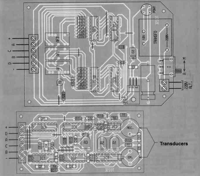
Component Placement
Start by soldering the interconnection straps. Then proceed with the resistors and diodes.
Next, install the sockets for the integrated circuits, followed by capacitors and the remaining components. Pay attention to the orientation of polarized components.
The displays should be mounted on 6-wrapper supports to elevate them and bring them closer to the case cover.
The ultrasonic transducers should be placed on the copper side. Also, ensure the correct correspondence of connections between the two modules.