An electronic touch organ is an intriguing musical device which produces very pleasant musical notes in response to finger touches on special touch sensitive electronic pads or buttons.
Modern day organs are, however, very costly which usually places these outside the reach of the majority of folks.
Low cost options types lack performance, and are in the form of chord organs which though work like polyphonic tend to be relatively minimal reed type equipment controlled with a little blower.
Title chord organ originates from the truth that the bass association is by means of control keys that produce the right note.
The lowest priced organ may be the so called monophonic organ(just one note could be played out at any given time) that is typically a bit more compared to pocket sized and is played using a stylus.
The very first apparent development essential would be to prepare an improved key pad set up since the stylus functioning can be quite a nuisance. However the £40 price of a full keyboard cannot be rationalized.
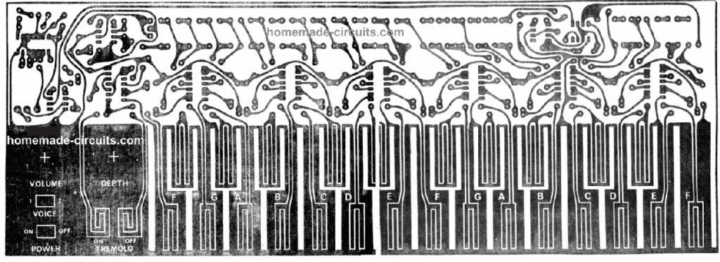
As is visible through the pictures the new keyboard continues to be of the touch type but has now been fashioned in order that the organ is played by just touching the proper pads, just as a full scale musical instrument.
Tremolo is additionally supplied which too is started up and off through contact pads and a control is given to adjust tremolo depth.
Another enhancement is in the precision of the tuning, that in the earlier instrument had been different within the keyboard because of the one-only resistor accustomed to increment between each note.
In the innovative model tuning on the keyboard is a lot superior by making use of a pair of resistors, where required in series or parallel, to get the closest possible to the accurate value of resistance.
Lastly the instrument features a couple of voices or stops that add significantly to the selection of the music which may be generated.
This small organ is pretty affordable to construct, really should give you a immense amount of satisfaction and is musically and electronically informative.
CONSTRUCTION
The keyboard structure of this electronic touch organ is imprinted straight onto the PCB that additionally holds the remainder of the elements.
Since the copper tracks of the keyboard might easily get corroded due to consistent touching with the finger it is very important for your PCB to be either tinned or shielded with some form of plating which will avoid tarnishing.
Begin construction by installation the LM380 into place after which fix small heatsink fins, as demonstrated in the image to both area of the IC. Solder these to pins 3, 4, 5 on a single side and pins 10, 11 and 12 on the other.
This should be accomplished first since there may be very little space in this region of the PCB. When various other parts have been in soldered in position.
Attach the two wire links and" put together the low-height parts to the board as indicated on the overlay.
Put the rest of the ICs last of all and consider specific attention not to play with the CMOS ICs too much prior to installation.
Examine the polarities of polarized parts such as lCs, capacitors and diodes just before soldering them into place.
In order to avoid getting screws getting visible on the keyboard stick the two switches into place with five-minute epoxy glue.
Apply some wooden or metal at the rear of each installation hole to attain added gluing surface area and more durability.
Attach the potentiometers and wire to finish PCB as specified in the overlay picture.
The whole unit must at this point be tested to make sure that all notes and features are functioning effectively prior to mounting inside of appropriate cases
DESIGN FEATURES
As I have said previously the fundamental characteristic is the execution of the keyboard using a finger touch method as opposed to the"probe" type.
Therefore some technology has to be related to every key to recognize that it has been touched.
Touch control of the touch organ is normally impacted by the capacitive, resistive or 50 Hz injection procedures.
While the capacitive technique is the most effective among these. This is usually the most high-priced and therefore is not employed.
The 50 Hz injection method is actually likewise sophisticated and therefore the resistive method was regarded as the only real useful method from a price tag viewpoint.
As the keyboard is currently played by the finger this also has to be bigger than normal even though still not really large like a full fledged keyboard.
In the original theory an OM802 IC had been used as the tone oscillator. This became substituted by a 555 timer lC because this is less expensive and more reliable in its results.
The 555 has a couple of outputs which could be applied, a sawtooth wave and a narrow pulse.
Both these outputs are utilized within our layout to offer diverse sounds for the instrument.
The sawtooth is filtered through a straightforward RC filter to get rid of several of the harshness because of the harmonic framework and the resulting tone of voice has a vibrant flute like audio.
The pulse output is combined in amount to the sawtooth using a resistive attenuator but is in any other case goes unfiltered. This tone of voice features a string-like noise.
Filtering has been retained extremely basic, yet again from a price point of view. If the user wishes this individual may possibly test out various filters in order to obtain various sounds.
With traditional organs the stop-filtering is completed for each octave of the organ to circumvent unnecessary tone and level alterations at unique frequencies.
With the 2 octave period of this organ several changes in tone and level has to be acknowledged within the range of the keyboard while working with the simple filters.
As attenuating filters are employed a good deal of gain is essential in the audio output stage and hence, an LM380 op amp amplifier is employed in the audio output stage to operate the loudspeaker optimally.
Circuit Diagram

How to Operate
How to operate the organ is going to be explained by looking at independently the 5 sections of that it is made up of.
These are:
- (a) Keyboard
- (b) Oscillator
- (c) Filter
- (d) Output amplifier
- (e) Tremolo circuit
(a) Keyboard: In contrast to the traditional touch organs the keyboard is controlled by the finger skin resistance and not by a probe.
Each key features a CMOS gate connected with it exactly where the two inputs to the gate tend to be linked together and with the positive supply through a 4.7 M resistor.
As soon as the key is touched the inputs of the gate are drawn low (0V) through the 100 k resistor resulting in the output of the gate to go high.
This drags the subsequent part of the resistor string high through the diode.
Therefore by choosing and touching various keypads we link different levels of resistances across pins 2 and 6 of the 555 oscillator and the positive supply, consequently activating it and altering the frequency determining time constant circuit.
(b) The Oscillator: The oscillator is dependent on a 555 timer lC. The capacitor Cl is charged up through a portion of the resistor string (as by the keyboard) along with the resistor R113.
If the voltage at pins 2 and 6 gets to that level which is set at pin 5. the capacitor is forced to discharg quickly through R97 and an enclosed transistor attached to pin 7 of the 555.
Once the voltage across C1 reaches down to half of what was set at pin 5, the internal transistor of the IC 555 is switched OFF and the capacitor is allowed to charge once again, hence continuing the cycle and producing a sawtooth waveform across the capacitor.
This waveform features a rich harmonic material but is produced with a high-impedance level. A unity gain buffer is as a result applied (IC8) to counteract this output from being loaded by the subsequent circuit stages.
A second output of a narrow pulse waveform can be obtained at pin 3 of the 555 and this is utilized to create the second tone of voice for the instrument.
(c) Filter: Several different filters had been experimented with however from a cost viewpoint it absolutely was difficult to validate anything more than a basic RC filter on the sawtooth which provides an amazingly relaxing flute-like outcome.
As the narrow pulse sequence appears fairly similar to strings it is basically attenuated to complement the amount of the filtered sawtooth.
(d) The Output Amplifier: The loudspeaker is powered by an LM380. Volume control is furnished by using potentiometers RVI and the necessary voice is determined through the switch SW1.
The LM380 must be fixed with heatsink fins as explained in the design.
(e) The Tremolo Circuit: Tremolo is generated by technique of a low frequency oscillator operating at around 8 Hz (IC11). The oscillator could be switched on and off by using the flip flop established by gates IC7/3 and lC7/4.
This flip flop is adjusted to the ‘on’ or ‘off setting through touch switches that run in the identical way as the principal keyboard. To improve tremolo frequency cut down R10 and vice versa.
The output from the tremolo oscillator is filtered by C12 and R109 to present a softer waveform and the resultant waveform buffered by IC12.
The gain of C12 is variable through RV2 and this particular knob as a result changes the depth of the tremolo modulation.
The potentiometer RV3 is actually a trim potentiometer that efficiently tailors the output from IC12 to pin 5 of the 555 and therefore the frequency of the organ.
In case it is felt necessary to move the keyboard upward or downward an octave or so this can be accomplished by transforming the value of C1 with a factor of two.
If the keyboard tuning happens to get skewed (when tuned accurately at the center one end of the keyboard is lower while the other is higher) this can be corrected by altering the value of R97.
When it is too sharp at the lower end reduce R97 while if it sounds flat at the lower end increase R97.
PCB Design

Parts List

Simple 3 Transistor Electronic Organ Circuit

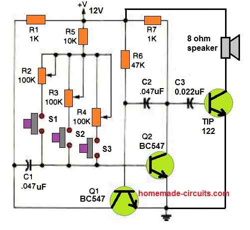
If you find the above electronic organ circuit too daunting or difficult, then you can perhaps go for this simple design.
It is a simple 2 transistor oscillator circuit having 3 adjustable frequency ranges for generating 3 distinct tone frequencies over the output speaker.
The TIP122 works like a audio amplifier and amplifies the frequency generated by the oscillator circuit stage.
The 3 push buttons can be pressed as desired for generating 3 unique sound tones at the output.
The individual pots associated with the push buttons further allow varying the tone frequency as required by the user.
Although only 3 frequency ranges are provided in the circuit, the push button and the pots can be increased to any desired numbers for getting a diverse range of frequency outputs for this organ.
Simple Organ Circuit using IC 4011
Given the current financial climate, this circuit might pique the interest of parents facing requests from their children for a stylophone.

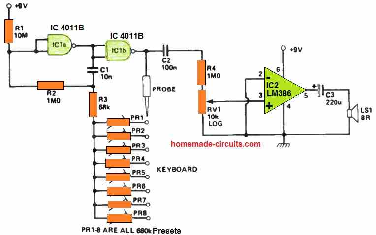
It incorporates a straightforward oscillator using two CMOS NAND gates (half of a 4011 chip).
Under normal conditions, the circuit remains silent. However, when the stylus touches the keyboard, it completes a connection through the chosen preset, causing the oscillator to generate a square wave signal.
This signal is then sent to the output stage, which features an LM386 integrated circuit.
The LM386 is an excellent choice for this application as it has a maximum output capacity of 200 mW and a low quiescent current draw of 3 mA.
Additionally, both ICs can operate with battery voltages as low as 4 V, ensuring a reasonably long battery lifespan.
To create a keyboard for this organ, a simple one can be fashioned from a piece of 0.15" matrix Veroboard with specific tracks removed.
For tuning purposes, a digital frequency meter is the most convenient tool, but in the absence of one, the instrument can also be tuned by ear using a reference such as a piano.
Hi Boys ! Been reading many stuffs about organs .Most people stuck in a question about TOG and divide down chips , etc. . What about , if we can make it more simple like a poly Synth !? 8 -10 ” voice cards ” with sine, saw , (?) Osc , attack / decay Vca . Global non self oscillating filter , global Lfo to pitch for vibrato . MIDI keyboard or key bed ( dipend what we want – compact instrument or , what ewer ) with CV, trigger / gate converter. Only draw bars will be a great deal !?
Hi sir. Can I use resistors 1/4 watt in Organ Circuit ?
Hi Mehrdad, yes you can use 1/4 watt resistors.
Hi Swagatam! I am an architect and musician in Cape Town, South Africa. I have a project – I am building a MIDI/eletronic organ from an old upright piano keybed. I’ve seen it done online. I’m good with my hands (model building, woodwork, metalwork, etc) and not intimidated by schematics, because I spend hours looking at complicated architectural and engineering drawings everyday. I do need assistance with designing a schematic that can work for MIDI or switch to Electronic organ. Currently looking at VOX/Jenner continental/Jaguar schematics, because I would want to create that tone. To play when I dont feel like plugging in to a DAW>Audio Interface>Laptop. But when I do plug into above – I can access a world of VST tones/samples and play on fully weighted timber keys. Would you be interested in helping me design the schematics for this project. I will then build it for a musical project here in Cape Town. I purchased the piano I will be deconstructing yesterday so Hope to do my research and get going on the MIDI/Organ schematics soon.
Hi Mike, I appreciate your interest in building an electronic organ, and I truly wish I could assist you in drawing the schematic, however an electronic organ schematic could be quite elaborate and lengthy, so it may be difficult for me to complete it for you due to work pressure. Nevertheless, if you get stuck and have problems somewhere, do let me know I will do my best to sort it out for you!!
create Electronic Drums circuit diagram
If possible I’ll try to post it!
Hi sir i,am your fan from pakistan .i,am an electronic eng and i like your totlal post .your ideas are verrrrrry verrry useful.sir why know urdu language?
Glad you liked my site Fayyaz, sorry I don’t know urdu!